Copyright © 2014 IJECCE, All right reserved
Optimal Performance of OFDM Signal using PAPR
Reduction Techniques in LTE Systems
Patteti Krishna
Research Scholar,JNTUH College of Engineering College, Hyderabad, Telangana, INDIA
Email: [email protected]
Kalitkar Kishan Rao
Director,Vaagdevi College of Engineering, Warangal, Telangana, INDIA Email: [email protected]
Tipparti Anil Kumar
Professor, Department of ECE, SR Engineering College, Warangal,Telangana, INDIA Email: [email protected]
Abstract – 3rd Generation partnership project Long term
Evolution (LTE) has been designed to provide more efficient use of radio networks. The LTE provides scalable bandwidth, latency reduction and higher data rates with improved mobility .Single carrier Frequency Division Multiple Access (SC-FDMA) has been selected for use in the Long Term Evolution (LTE) uplink due to its Peak-to-Average Power Ratio (PAPR) relative to OFDMA. The SC-FDMA scheme normally applies 16-Quadrature Amplitude Modulation (16-QAM),but amplitude phase shift keying(APSK) modulation has a lower PAPR than the 16-QAM,resulting in improved BER. This paper presents the DFT Spreading and Pulse shaping gives better performance with compare to selected mapping (SLM), Partial Transmit sequence (PTS), the 16-APSK modulation scheme and its effects on BER through its effects on the PAPR.
Keywords – 16-APSK, 16-QAM, SC-FDMA, LTE, SLM,
PTS, DFT and PAPR.
I.
I
NTRODUCTION3GPP Long Term Evolution or LTE is a standard that has been developed by the 3rd Generation Partnership Project (3GPP), to become a truly global mobile standard and to apply to high-speed wireless data transmission for mobile phone and data terminal. In order to reduce the interference signals and to improve the channel capacity of the LTE system, orthogonal frequency division multiple access (OFDMA) and single carrier frequency multiple access (SC-FDMA) are employed for the downlink and uplink, respectively. The SC-FDMA is the multiplexing technique for the LTE uplink because its PAPR is lowers than that of other transmission techniques, especially, OFDMA.
The high PAPR is a principal weakness of OFDM. It brings on the signal distortion in the nonlinear region of high power amplifier (HPA). The closer the HPA is operated to the saturation region, the more frequent are excursions into the nonlinear region and the more pronounced is the signal distortion. The signal distortion induces the degradation of bit error rate (BER). Therefore, it is desirable to have low PAPR to improve the BER performance.
To reduce the PAPR of OFDM, there are mainly two categories, which are signal scrambling techniques and signal distortion techniques. The practical solutions of the signal scrambling techniques include block coding, Selective Level Mapping (SLM), and Partial Transmit Sequences (PTS). The signal distortion techniques include clipping, peak windowing, peak cancellation, peak power
suppression, weighted multicarrier transmission, companding, etc.
This paper will present the investigation and performance of SLM, PTS, DFT-Spreading and DFT with Pulse shaping Techniques, the 16-APSK modulation used in the LTE uplink system with the nonlinear distortion due to a HPA.
The paper is organized as follows .First; the effects of the constellation ring ratio of the 16-APSK modulation, on both the PAPR are presented in Section II. Section III shows the description of the system model adopted for the analysis and the simulation. Then, the PAPR Reduction Techniques explained in section IV, simulation results are shown in section V. Finally, section VI provides conclusions.
II.
E
FFECTS OFAPSK
C
ANCELLATIONR
INGR
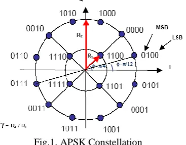
ATIOAmplitude phase shift keying (APSK) is a digital modulation scheme that conveys data by changing or modulating both the amplitude and the phase. It is a combination of Amplitude shift keying (ASK) and Phase shift keying (PSK) applied to more effectively populate the signal space. Its constellation is composed of concentric rings, each with uniformly spaced PSK points. Fig. 1 shows an example of 16-APSK constellation which has 2 concentric rings, with 4 PSK points in the inner and 12 PSK points in the outer. The effects of its constellation ring ratio on PAPR and BER could be analyzed as following.
Fig.1. APSK Constellation
A.
The Effects on PAPR
𝑃𝐴𝑃𝑅 =
max𝑚 =0,1…𝑁𝐿 𝑥(𝑚 ) 2𝐸 𝑥 𝑡 2 (1)
Generally, the output signals after IFFT are random because the input data samples are random. The highest PAPR occurs only when n (n<N) modulated signals have the same phase. In this case, the peak power would be the sum of the power of these signals. Since the PAPR is a random variable, in all literatures, Complementary Cumulative Distribution Function (CCDF) is the most common way to evaluate the statistic properties of PAPR by estimating the probability of PAPR when it exceeds a certain level PAPR0. The CCDF of the PAPR is defined
as CCDF= P 𝑃𝐴𝑃𝑅 > 𝑃𝐴𝑃𝑅0
This is the simulation of OFDM system to observe PAPR in it. So this is the basic explanation about PAPR and why it is reduce in OFDM system. Now there are different techniques has been proposed for the reducing PAPR in OFDM system. For 16-APSK modulation, there are many types of constellation patterns, such as 4+12 ASPK, 5+11 ASPK, and 6+10 APSK. Each type assigns a different number of points to each ring, with the total number of points summing to 16.The average power level of the 4+12 APSK, which has the constellation mapping shown in Fig. 1, can be defined as
E3= 𝑅12+3𝑅22
4 (2)
Where R1 is radius ring and R2 is outer radius ring.
Fig. 2: Block diagram of the SC-FDMA system with APSK modulation
III.
S
YSTEMM
ODELFig. 2 shows the block diagram of the general SC-FDMA system with the APSK modulation. The binary sequence is modulated into data symbols, C (n), by using the 4+12 APSK modulation scheme. Then, a block of N modulated symbols is applied to the N-point Discrete Fourier Transform (DFT) to produce a frequency domain representation, D (k).
𝐷 𝑘 = 1
𝑁 𝐶(𝑛)𝑒
𝑗 2𝜋𝑛𝑘 /𝑁 𝑁−1
𝑛=0 (3)
This output is fed to the Localized FDMA (LFDMA) subcarrier mapping block, which is the subcarrier mapping used in the LTE standard. At this point, each of the N-DFT outputs is mapped to one of M orthogonal subcarriers (M>N) as
𝑆 𝑘 = 𝐷 𝑘 0 ≤ 𝑘 ≤ 𝑀 − 1
0 𝑜𝑡ℎ𝑒𝑟𝑤𝑖𝑠𝑒 (4) Then, the M-point inverse DFT (IDFT) transforms these data symbols into the time-domain samples, T(t), of these subcarriers.
𝑇 𝑡 = 1
𝑀 𝑆(𝑘)𝑒
𝑗 2𝜋𝑘 /𝑀 𝑀−1
𝑘=0 (5)
Similar to OFDM, the cyclic prefix is added to the symbols. Before entering the AWGN channel, the transmitted signal is amplified by the high power amplifier (HPA), which makes the overall channel nonlinear.
IV.
PAPR
R
EDUCTIONT
ECHNIQUESPAPR reduction techniques are classified into the different approaches: clipping technique, coding technique, probabilistic (scrambling) technique, adaptive pre-distortion technique, and DFT-spreading technique.
A.
Selective Mapping
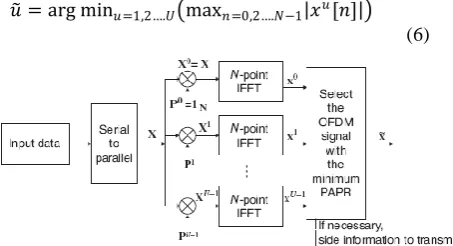
Figure 3 shows the block diagram of selective mapping (SLM) technique for PAPR reduction. Here, the input data block 𝑋 = [ 𝑋 0 , 𝑋 1 , … … . . 𝑋 𝑁 − 1 is multiplied with U different phase sequences 𝑃𝑢 = 𝑃
0𝑢, 𝑃1𝑢… … … 𝑃𝑁−1𝑢
where 𝑃𝑣𝑢 = 𝑒𝑗 𝜑𝑣
𝑢
and 𝜑𝑣𝑢 ∈ (0,2𝜋) for v=0,1…..N-1 and
u= 1,2……U which produce a modified data block 𝑋𝑢 = 𝑋𝑢 1 , 𝑋𝑢 2 … … . . 𝑋𝑢 𝑁 − 1 𝑇 among which
the one 𝑥 = 𝑥𝑢 with the lowest PAPR is selected for
transmission is
𝑢 = arg min𝑢=1,2….𝑈 max𝑛=0,2….𝑁−1 𝑥𝑢[𝑛]
(6)
Fig.3. Block diagram of selective mapping (SLM) technique for PAPR reduction.
B.
Partial Transmit Sequence
The partial transmit sequence (PTS) technique partitions an input data block of N symbols into V disjoint sub blocks as follows
𝑋 = [ 𝑋0, 𝑋1, … … . . 𝑋𝑉−1] T
(7) where Xi are the sub blocks that are consecutively located and also are of equal size. Unlike the SLM technique in which scrambling is applied to all sub carriers, scrambling (rotating its phase independently) is applied to each sub block in the PTS technique (see Figure 4). Then each partitioned sub block is multiplied by a corresponding complex phase factor 𝑏𝑣= 𝑒𝑗𝜑𝑣 v=1,
2…..V subsequently taking its IFFT to yield 𝑋 = 𝑉 𝑏𝑣𝑥𝑣
𝑣=1 (8)
Where { 𝑥𝑣} is referred to as a Partial Transmit
Sequence (PTS).The phase vector is chosen so that the PAPR can be minimized as follow as
𝑏 1… … … . . 𝑏 𝑉 = arg min 𝑢=1,2….𝑈
max
𝑛=0,2….𝑁−1 𝑏 𝑣𝑥𝑣[𝑛] 𝑉
𝑣=1
(9) Then, the corresponding time-domain signal with the lowest PAPR vector can be expressed as
𝑥 = 𝑉 𝑏 𝑣𝑥𝑣
Copyright © 2014 IJECCE, All right reserved Fig.4. Block diagram of partial transmit sequence (PTS)
technique for PAPR reduction.
C.
DFT Spreading
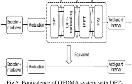
Figure 5, suppose that DFT of the same size as IFFT is used as a (spreading) code. Then, the OFDMA system becomes equivalent to the Single Carrier FDMA (SC-FDMA) system because the DFT and IDFT operations virtually cancel each other. In this case, the transmit signal will have the same PAPR as in a single-carrier system.
Fig.5. Equivalence of OFDMA system with DFT-spreading code to a single-carrier system.
In OFDMA systems, sub carriers are partitioned and assigned to multiple mobile terminals (users).Unlike the downlink transmission, each terminal in uplink uses a subset of sub carriers to transmit its own data. The rest of the sub carriers, not used for its own data transmission, will be filled with zeros. Here, it will be assumed that the number of sub carriers allocated to each user is M. In the DFT-spreading technique, M-point DFT is used for spreading, and the output of DFT is assigned to the sub carriers of IFFT. The effect of PAPR reduction depends on the way of assigning the sub carriers to each terminal. As depicted in Figure 6, there are two different approaches of assigning sub carriers among users: DFDMA (Distributed FDMA) and LFDMA (Localized FDMA). Here, DFDMA distributes M DFT outputs over the entire band (of total N sub carriers) with zeros filled in N-M unused sub carriers, whereas LFDMA allocates DFT outputs to M consecutive sub carriers in N sub carriers. When DFDMA distributes DFT outputs with equi-distance N/M=S, it is referred to as IFDMA (Interleaved FDMA) where S is called the bandwidth spreading factor.
Fig.6. Sub carrier mapping for uplink in OFDMA systems: DFDMA and LFDMA.
The input data 𝑥 𝑛 is DFT-spread to generate 𝑋 𝑖 and then, allocated as
𝑋 𝑘 = 𝑋 𝑘
𝑆 , 𝑘 = 𝑆. 𝑚1.𝑚1= 0,1,2 … . 𝑀 − 1 0 𝑜𝑡ℎ𝑒𝑟𝑤𝑖𝑠𝑒
(11) The IFFT output sequence 𝑥 𝑛 with n = M.s + m, for s= 0, 1, 2…..S-1 and m=0, 1, 2…..M-1 can be expressed as
𝑥 𝑛 = 1
𝑁 𝑋 [𝑘]
𝐾
𝑘=0
𝑒𝑗 2𝜋𝑛𝑁𝑘 =1
𝑆 1
𝑀 𝑋[𝑚1]
𝑀−1
𝑚1=0
𝑒𝑗 2𝜋𝑀𝑛𝑚1
(12)
D.
Pulse Shaping
Pulse shaping using Raised Cosine filter is taken after IFFT stage for LFDMA technique. Pulse shaping is used to minimize Inter symbol Interference (ISI) and results in better transmission of OFDM signals. The optimum value of Roll off factor α is chosen for obtaining better Simulation results.
V.
R
ESULTA
NALYSISA.
Peak to Average Power Ratio (PAPR) Analysis
The Peak-to-Average Power Ratio (PAPR) is analyzed by using Complementary Cumulative Distribution Function (CCDF). The CCDF of PAPR, which is the probability that PAPR is higher than a certain PAPR value PAPR0 (Pr (PAPR >PAPR0)), for N subcarriers of an
OFDM multi-carrier signal can be calculated by Pr (PAPR
>PAPR0= 1- 1 − 𝑒−𝑃𝐴𝑃𝑅 0 𝑁 , Where N is the number of
subcarriers, PAPR0is the clipping level in the nonlinear
system.
The CCDF is measured by using the Monte Carlo simulation for the system applying the 16-APSK (4+12 APSK) modulation with various values of ring ratios in the nonlinear system with IBO of 1 dB and 2 dB. The comparison of the CCDF of PAPR for the ring ratios of 1.1, 2, 2.5, 2.75, 3, 3.5, 4, and 7 is shown in Fig. 7 and Fig. 8. At the 99 percentile that the Pr (PAPR >PAPR0) is less
Fig.7. CCDF of PAPR for the nonlinear system with IBO of 1 dB and various ring ratios
Fig: 8. CCDF of PAPR for the nonlinear system with IBO of 2 dB and various ring ratios
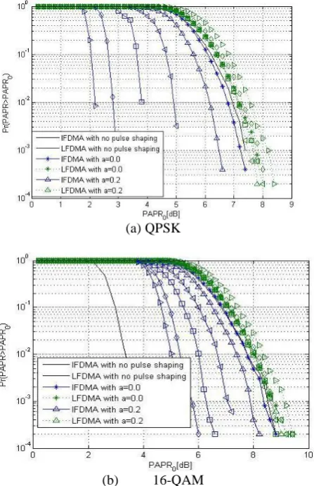
Fig: 9 shows a comparison of PAPR performances when the DFT-spreading technique is applied to the IFDMA, LFDMA, and OFDMA. Here, QPSK, 16-QAM, and 64-QAM are used for an SC-FDMA system with N = 256, M = 64, and S = 4. It can be seen from Fig 9 that the PAPR performance of the DFT-spreading technique varies depending on the sub carrier allocation method. In the case of 16-QAM, the values of PAPRs with IFDMA, LFDMA, and LFDMA for CCDF of 1% are 3.5dB, 8.3dB, and 10.8dB, respectively. It implies that the PAPRs of IFDMA and LFDMA are lower by 7.3dB and 3.2dB, respectively, than that of OFDMA with no DFT spreading. Now, let us consider the effect of pulse shaping on the PAPR performance of DFT-spreading technique. Fig 6 shows the PAPR performance of DFT-spreading technique with IFDMA and LFDMA, varying with the roll-off factor α of the RC (Raised-Cosine) filter for pulse shaping after IFFT. It can be seen from this figure that the PAPR performance of IFDMA can be significantly improved by increasing the roll-off factor from α = 0 to 1. This is in contrast with LFDMA which is not so much affected by pulse shaping. It implies that IFDMA will have a trade-off between excess bandwidth and PAPR performance since excess
bandwidth increases as the roll-off factor becomes larger. The results here have been obtained with the simulation parameters of N = 256, M = 64, S = 4 (spreading factor), and Nos = 8 (over sampling factor for pulse shaping) for
both QPSK and 16-QAM.
(a) QPSK
(b) 16-QAM
( c) 64-QAM
Fig.9. PAPR performances of DFT-spreading technique for IFDMA, LFDMA, and OFDMA.
Copyright © 2014 IJECCE, All right reserved a of the RC (Raised-Cosine) filter for pulse shaping after
IFFT. It can be seen from this Fig 5 that the PAPR performance of IFDMA can be significantly improved by increasing the roll-off factor from 𝛼 = 0 to 1. This is in contrast with LFDMA which is not so much affected by pulse shaping. It implies that IFDMA will have a trade-off between excess bandwidth and PAPR performance since excess bandwidth increases as the roll-off factor becomes larger. The results here have been obtained with the simulation parameters of N = 256, M = 64, S = 4 (spreading factor), and Nos = 8 (oversampling factor for
pulse shaping) for both QPSK and 16-QAM.
(a) QPSK
(b) 16-QAM
Fig.10. PAPR performances of DFT-spreading technique with & without pulse shaping.
Fig.11. PAPR performance of DFT-spreading technique when Nd varies.
Further, let us see how the PAPR performance of DFT-spreading technique is affected by the number of subcarriers, M, that are allocated to each user. Fig 11 shows that the PAPR performance of DFT-spreading technique for LFDMA with a roll-off factor of a 𝛼 = 0:4 is degraded as M increases, for example, Nd =4 to 128. Here,
64-QAMis used for the SC-FDMA system with 256-point FFT (N=256).
Table 1: Parameters for simulations of DFT-Spreading
Parameter Values
Bandwidth 1.4MHZ
FFT Size (N) 256
No. of the subcarriers per users (M)
64
Spreading factor(S) 4 No. of OFDM Symbols per 1 ms
14- normal Cp,12- extended CP
Modulations QPSK,16-QAM & 64-QAM
VI.
C
ONCLUSIONLTE technology is attractive in the telecommunications industry due to the high speed data transfer rate it offers. Therefore, the modulation techniques must be selected properly as an important consideration because it can push the system to its fullest potential. The APSK modulation works better in terms of both BER and PAPR performances than QAM in the nonlinear system. In conclusion, the SC-FDMA systems with IFDMA and LFDMA have a better PAPR performance than OFDMA systems. This unique feature has been adopted for uplink transmission in 3GPP LTE, which has been evolved into one of the candidate radio interface technologies for the IMT-Advanced standards in ITU-R. Although the IFDMA has a lower PAPR than LFDMA, the LFDMA is usually preferred for implementation. It is attributed to the fact that sub carriers allocation with equi-distance over the entire band (IFDMA) is not easy to implement, since IFDMA requires additional resources such as guard band and pilots.
R
EFERENCES[1] “Work Plan 3GPP (Release 8)”, 16 January 2012, Retrieved 1 March 2012.
[2] W.-K. F. Khan, LTE for 4G Mobile Broadband Air Interface Technologies and Performance, Cambridge University Press, 2009.
[3] J. Gazda, D. Dupak and D. Kocur, “M-APSK modulation for SC-FDMA communication systems,” Radioelektronika (RADIOELEKTRONIKA), 2011 21st International Conference, 2011, pp. 1-4
[4] Y. Huang and Z. Zeng, “A Simplified Peak Cancellation Method for OFDM Signals,” 2012 International Conference on Computer Science and Electronics Engineering, Mar. 2012, pp. 336–339
[5] J. Sebesta, “Efficient Method for APSK Demodulation,” Proceedings of the 3rd International Conference on Circuits Systems and Signals (CSS'09), 2009, pp. 187-190.
[6] G. Hill, “Peak Power Reduction in Orthogonal Frequency Division Multiplexing Transmitters,” PhD. thesis, Victoria University of Technology, Melbourne, Australia, March 2011. [7] Malhar Chauhan, Saurabhpatel, Hardikpatel, “Different
International Journal of Engineering Research and Applications, Vol. 2, Issue 3, May-Jun 2012
[8] N. R. Raajan, S. Prabha and D. Meenakshi, “Improved Performance in OFDM Systems by PAPR Reduction Techniques”, International Conference on Computer Communication and Informatics, Jan.04- 06, 2013
[9] Y.-C. Wang and Z.-Q. Luo, “Optimized Iterative Clipping and Filtering for PAPR Reduction of OFDM Signals”, IEEE Transaction on Communications, Vol. 59, No. 1, January 2011.
[10] K. Bani, R. Bansode, and B.K. Mishra, “Novel Technique for PAPR Reduction in OFDM System Using n/4-shifted-DQPSK Modulation & Turbo Code,” Devices, Circuits and Systems (ICDCS), 2012 International Conference, 15-16 Mar. 2012, pp. 627–633.
A
UTHOR’
SP
ROFILEPatteti Krishna
Completed B.Tech degree in Electronics and Communication Engineering and M.Tech degree with specialization of Digital Systems & Computer Electronics from JNT University, Hyderabad in 2005 and 2008. He is having 9 years of teaching experience and published papers in various International & National journals. At present Krishna is pursuing PhD in wireless Communications under faculty of Electronics & Communication Engineering. His research interests are Signal processing for Wireless Communications, MIMO Communications and Multiuser MIMO Communications. He is a Member of IEEE, ISTE and IETE.
Kalithkar Kishan Rao
is currently a Professor in Electronics and Communication Engineering Department, Viswambhara Educational Society. He received his B.E. and M.E. degrees from Osmania University in 1965 and 1967. He obtained his PhD degree from Indian Institute of Technology, Kanpur in 1973.He worked as Principal for National Institute of Technology, Warangal and Kakatiya Institute of Technology and Science, Warangal. He is a senior member of IEEE and fellow of IETE. He has published over 78 International articles. He currently serves as Editor for International Journal of Wireless Personal communication, Springer and International Journal of Wireless Networks, Springer. He guided 03 PhD scholars and 62 Master Projects. His research interests are Wireless Communications, Signal Processing Applications and Cooperative Mobile Communications.