EFFICIENCY AND DURABILITY OF WEARABLE SMART
MATERIALS AND STRUCTURES
DIMITROULA
MATSOUKA
EFFICIENCY AND DURABILITY OF WEARABLE SMART
MATERIALS AND STRUCTURES
BY
DIMITROULA
MATSOUKA
THIS THESIS IS SUBMITTED TO THE UNIVERSITY OF BOLTON
IN PARTIAL FULFILMENT OF THE REQUIREMENT FOR OF THE
DEGREE OF DOCTOR OF PHILOSOPHY
COLLABORATING ESTABLISHMENT:
PIRAEUS UNIVERSITY OF APPLIED SCIENCES
[i]
DECLARATION
I, hereby, declare that the thesis is based on my original work except for
standard definitions, quotations and citations which have been duly
acknowledged, I also declare that it has not been previously or concurrently
submitted for any other degree at any stage of learning or other institutions.
Contribution of co-authors
The following people are acknowledged as co-authors of the papers
published as a requirement for the PhD program.
➢
Professor Elias Siores, PhD supervisor at Bolton University
➢
Professor Savvas Vassiliadis, PhD supervisor at Piraeus University
of Applied Sciences
➢
Professor Derman Vatansever Bayramol at Namik Kemal
University, Turkey. Professor Vatansever was involved in the
production of the piezoelectric fibres at Bolton University.
➢
Dr Navneet Soin, post-doctoral research fellow at Bolton University.
Dr Soin, offered guidance on polymer material analysis, mainly
HPLC, FTIR and DSC measurements and carried out the
measurements at Bolton University.
[ii]
➢
Professor Stylianos Mitilineos at Piraeus University of Applied
Sciences.
Professor Mitilineos
offered guidance on the
measurement of capacitance of materials.
[iii]
DEDICATION
for them that come after.
[iv]
ABSTRACT
Piezoelectric polymer materials have been under investigation since the 1970’s
starting with the discovery of the piezoelectric effect in PVDF films by Kawai.
Since then the piezoelectric effect has been detected among other polymers in
polyureas, polyamides, and polypropylene and their copolymers. While the
investigation of the piezoelectric effect was largely carried out on the film form of
the polymers since 2010 interest has developed into the production methods,
properties and applicability of melt spun piezoelectric textile fibres made of these
polymers. The application of piezoelectric fibres could have a significant impact
in wearable textiles as sensors, actuators, or energy harvesting modules. Current
research is mostly centred onto production methods and fibre crystallinity
characterization.
The research carried out in this PhD by publication project is concerned with
piezoelectric textile fibres as electrically active elements. As such the research
focused on the electrical behaviour of the fibres. The work carried out was
three-fold.
Specifically, wearable textile materials undergo cleaning/ care treatments that are
intrinsic to their function as wearables. These treatments may include washing,
dry cleaning or sponging. Washing (cleaning treatment in a solution mainly
containing water and an appropriate detergent at an elevated temperature or
room temperature) is a common cleaning method. The effects of washing cycles
on melt spun piezoelectric fibres remain under-investigated. For the first part of
the research, piezoelectric melt spun fibres (PVDF, PP and PA-11) with two
different cross sections (circular and rectangular), were mechanically stimulated
by a rotating fin that impacted the fibres periodically. The resulting Vp-p (peek to
peek voltage), was measured on the original fibres and on the fibres following one
[v]
results of this part of the research it was shown that the washing cycle effected
the voltage response of the fibres depending on the fibre cross section and the
fibre composition. The results of the research were presented in a paper titled
“Investigation of the durability and stability of piezoelectric textile fibres” published
in the Journal of Intelligent Materials Systems and Structures.
For the second part of the research, it was noted that according to the existing
literature the research approach for the determination of the electrical response
of the fibres utilized exclusively the measurement of the voltage produced by
mechanical excitation of the fibres, in open circuit conditions. This approach is not
sufficient to satisfactorily characterise the electrical behaviour of the fibres as
power generating elements. By contrast, a sufficient measurement is the power
production of the fibres as this also includes a measurement of the current
produced. In order to supply these measurements a testing apparatus/
methodology was developed. The apparatus consists of a measuring station
where the voltage and current produced are measured, and a means for periodic
mechanical stimulation of the specimens. The equipment was used to determine
the power generated by piezoelectric melt spun fibres (PVDF, PP and PA-11) with
two different cross sections (circular and rectangular). The results of the research
were presented in a paper titled “On the Measurement of the Electrical Power
Produced by Melt Spun Piezoelectric Textile Fibres” published in the Journal of
Electronic Materials.
Finally, considering the underlying premise of integration of fully textile based
electronic components into textile substrates (e.g. wearable applications), 3D
knitted fabrics that incorporated piezoelectric melt spun fibres were investigated
with regards to their capacitive behaviour. Four different fabric structures were
examined (different composition of the outside layers and different thickness). The
[vi]
characteristics of the fabrics and the actual properties were determined using an
Impedance Analyzer. Based on the results it was found that the theoretical model
for the calculation of the capacitance of the samples appeared to be an acceptable
approximation for the behaviour of the fabrics. Also, the ability to customise the
required capacitance to suit the applications by specifying the dimensions of the
3D fabric and/or the density, the thickness or even the material of the interlaced
fibres has also been shown to be possible.
Moreover, reviewing the results of a resonance test for a purely textile based
parallel LC circuit, it was shown that it is possible to implement resonant circuits
that are convenient for basic electronic applications (i.e. oscillators, filters, etc.).
The results of the research were presented in a paper titled “Three-dimensional
weft-knitted textile fabrics-based capacitors” published in the Journal of the Textile
Institute.
This research project touched on some of the less thoroughly investigated
research areas connected to the efficiency and durability of piezoelectric melt
spun fibres and structures, with innovative results such as the development/
construction of the equipment that can be used for the measurement of the power
produced by piezoelectric textile fibres as well as the investigation of the
capacitive behaviour of the 3D knitted fabrics incorporating piezoelectric textile
fibres and the conclusion that resonance is possible to achieve in a purely textile
[vii]
ACKNOWLEDGMENTS
I would sincerely like to thank my supervisors; Bolton University’s Director of
Research and Innovation, Professor Elias Siores, and Professor Savvas
Vassiliadis and Professor Maria Raggoussi from the Piraeus University of Applied
Science for their support and guidance throughout the research programme.
I would like to especially acknowledge the continued guidance of Professor
Vassiliadis ever since our first encounter during my BSc years at the Piraeus
University of Applied Sciences. From that point on, he has been an invaluable
support and mentor in more than academic life and I consider myself immensely
blessed to have met him.
I would be remiss if I did not mention the gracious support and help offered by the
staff at the Piraeus University of Applied Sciences, New York College, and Bolton
University.
Vincent Van Gogh said that “Close friends are truly life's treasures. Sometimes
they know us better than we know ourselves. With gentle honesty, they are there
to guide and support us, to share our laughter and our tears. Their presence
reminds us that we are never really alone.” Michelle McAvoy, Paul
Sihvonen-Binder, and Pierre Albisser have not just shown themselves to be real friends but
they have acted more like family. Thank you. I can never repay you for your
support and real help. I am in your debt.
Finally, I would like to thank my family for their encouragement during this
[viii]
List of symbols
3D Three-dimensional
μm micrometre, 10-6meter
μW microwatt, 10-6 Watt
Ω Ohm
A area
BaTiO3 Barium titanate
BLE Bluetooth low energy
BS British Standards
0C degrees centigrade
C capacitance
CB carbon black
CH2 Methylene
cm centimetre, 10-2 metre
CNT/PP carbon nanotubes/ polypropylene
CuS Copper Sulphide
d distance
[ix] DMA dynamic mechanical analysis
DSC differential scanning calorimetry
DWNT double-wall carbon nanotubes
ε0 electric constant (vacuum permittivity)
εrf relative static permittivity (dielectric constant) (approx. 8.854×10⁻¹² F⋅m−1)
F Farad
FEM finite element method
FTIR Fourier transform analysis
HDPE high density polyethylene
Hz Hertz
ITO Indium tin oxide
kΩ kiloOhm,103 Ohms
kV kilovolt, 103 Volt
LED light emitting diode
LC inductor-capacitor
m metres
m2 square metres
m3 cubic meter
[x] mm millimetre, 10-3meter
MHz Mega Hertz, 106Hertz
MPa Mega Pascal, 106 Pascal
ms millisecond, 10-3 second
mW milliwatt, 10-3 Watt
mVp-p millivolt peak to peak
NCC nearest centroid classifier
NH2-DWCNT amino modified double-wall carbon nanotubes
nW nanowatt 10-9Watt
PA-11 polyamide 11
PEDOT/PSS poly(3,4-ethylenedioxy-thiophene)/poly(4-styrenesulfonate)
pF picofarad, 10-9Farad
PP polypropylene
Pt platinum
P(VDF70-TrFE30) poly(vinylidenefluoride-trifluoroethylene)
PVDF polyvinylidene fluoride
PZT lead zirconate titanate
[xi] RF radio frequency
rpm revolutions per minute
Rs real (ohmic) part of the resistance
SEM scanning electron microscopy
SiO2 Silicon dioxide
SR silicone rubber
UV ultraviolet
V Volt
Vp-p peak to peak voltage
Vf overall filament volume
W Watt
XRD x-ray diffraction
Xs imaginary part of the impedance
ZnSnO3 zinc stannate
[xii]
List of Figures
Figure 1. Classification of dielectric materials ... 9 Figure 2. Schematics of molecular structure of odd-numbered and
even-numbered polyamides ... 12 Figure 3. Schematic of continuous method of production of piezoelectric melt spun fibres ... 16 Figure 4. Possible structural phase transitions in fibrous PVDF, with the
causative processing conditions and experiments indicated. (Figure reproduced from Steinman et al. (2011)) ... 21 Figure 5. Diagram of the experimental set-up used for measuring the voltage produced by stimulation of piezoelectric fibres. ... 34 Figure 6. Typical voltage waveform produced during periodical stimulation ... 35 Figure 7. FTIR spectra of (a) PVDF monofilament, (b) PVDF ribbon yarn, (c) PA11 monofilament and (d) PP monofilament before ... 37 Figure 8. Peak-to-peak voltage generation of pristine (a) monofilaments and (b) ribbon yarns. ... 39 Figure 9. Peak-to-peak voltage generation of (a) ribbons and (b) monofilaments before and after washing ... 41 Figure 10. Bending mode diagram, L indicates the length of the piezoelectric fibre, W the width, T the thickness, P is the polarization, Fin is the bending force – including Voltage output indication. ... 41 Figure 11. Maximum Power Transfer ... 44 Figure 12. Schematic of the fibre clamping/ signal acquisition electrodes system mounted on the device. ... 46 Figure 13. Fibre clamping system with piezoelectric ribbon yarn specimen inserted and secured in place ... 47 Figure 14. Measurement principle ... 48 Figure 15. Power in Watts obtained from the yarns at 10 mm test length. (a) PVDF monofilament yarn, (b) PVDF ribbon yarn, (c) PP monofilament, (d) PP ribbon yarn, (e) PA-11 monofilament yarn. ... 51 Figure 16. Testing apparatus developed for the measurement of the electrical power produced by the piezoelectric fibres ... 53 Figure 17. Needle notation for the structure of the 3D fabric samples – yarn A is the conductive yarn, yarn B is the insulating yarn and yarn C is the
[xiii]
[xiv]
List of Tables
Table 1. Characterisation methods used in research papers originating in
Sweden ... 18 Table 2. Characterisation methods used in research papers originating in the UK ... 20 Table 3. Characterisation methods used in research papers originating in
Germany ... 22 Table 4. Characterisation methods used in research papers originating in
Portugal ... 24 Table 5. Characterisation methods used in research papers originating in
[xv]
Content
DECLARATION ... i
DEDICATION ... iii
ABSTRACT ... iv
ACKNOWLEDGMENTS ... vii
List of symbols ... viii
List of Figures ... xii
List of Tables ... xiv
Content ... xv
Chapter 1 Introduction ... 1
1.1 Research objectives... 3
Chapter 2 Literature review ... 5
2.1 Energy harvesting ... 5
2.2 Piezoelectricity ... 8
2.3 Melt-spun textile fibre materials as piezoelectric elements ... 14
2.4 Textile-element based capacitors... 28
Chapter 3 “Investigation of the durability and stability of piezoelectric textile fibres” ... 32
3.1. Materials - Methods ... 32
3.2. Results - Discussion ... 36
Chapter 4 “On the Measurement of the Electrical Power Produced by Melt Spun Piezoelectric Textile Fibres” ... 43
4.1. Introduction ... 43
4.2. Materials - Methods ... 45
4.3. Results-Discussion ... 48
Chapter 5 “Three-dimensional weft-knitted textile fabrics based capacitors” 54 5.1. Materials - Methods ... 54
5.2. Results-Discussion ... 61
Chapter 6 Discussions - Conclusions and Future work... 68
6.1 Future work ... 72
References ... 75
Appendix A ... 92
Appendix B ... 101
[1]
Chapter 1 Introduction
Energy harvesting materials and systems have emerged as a prominent research
area that continues to grow at rapid pace (Kong et al., 2014). The main reasons
behind this trend have to do with the continued miniaturization of electronic
devices, such as portable electronics, sensors, and transmitters that allows for
usage these electronics in applications that were previously incommodious and
inefficient. Such applications include but are not limited to wearables, implantable
devices and wireless sensor networks (military/ civilian applications).
What these applications have in common is the requirements/ restrictions
imposed on the power supply. Power supplies need to be portable, light, to have
small dimensions (comparable to the systems they are powering) and in several
of the applications they should preferably be able to provide uninterrupted power
without the need for replacement.
Implantable devices and wireless sensor networks are two prominent examples
that showcase this fact. In the case of the implantable devices the need for a
power source that will require minimum maintenance after installation is
self-evident. In the case of wireless sensor networks the dispersion, number of the
sensors, hence projected cost, and in certain applications the difficulty of
approaching their location imposes these restrictions on the power source (Li et
al., 2014; Priya and Inman, 2009).
Piezoelectric materials are very good candidates as energy sources for those
applications and for other applications that do not fall in the extremes of
[2]
Fabrication of wearable smart textiles imposes significant restrictions and
requirements onto the electrically active components that will be integrated into
the textile structure (whether truly integrated or simply “pasted” on). These
restrictions can be briefly described as the need for ruggedness of the
components (e.g. circuitry) defined as durability in mechanically demanding
environments during fabrication and use of smart textile in daily life as well as
unaltered comfort and washability by the integration of electronic circuits.
Regarding the power supply it should be light-weight and have a high capacity to
ensure uninterrupted use of the smart textile for a reasonably long time and not
to compromise the comfort parameters (Cherenack and van Pieterson, 2012)
Piezoelectric materials are divided into four categories: ceramics, single crystals,
polymers, and composites (the composite material is a combination of
piezoelectric ceramics or single crystals with polymers). When considering the
materials in a historic perspective, single crystals and ceramics were the oldest
materials used for piezoelectric applications with quartz being one of the oldest
materials used (Curie and Curie, 1880).
Piezoelectric polymers are the most recent materials to be investigated
(Hayakawa and Wada, 1973; Kawai, 1969) and piezoelectric melt spun textile
fibres started appearing in published research since approximately 2010 (Siores
et al., 2010). The development of piezoelectric textile fibres leads to appealing
opportunities of innovation in energy harvesting especially for wearable smart
applications. The abilities offered for full integration of the piezoelectric elements
to the textile substrate would resolve some the challenges mentioned in the
previous paragraphs.
This PhD project aims to investigate the electrical properties of piezoelectric melt
[3]
1.1 Research objectives
While piezoelectric polymer films have been under investigation since 1969 when
Kawai reported large piezoelectricity effect in PVDF films, textile piezoelectric
melt-spun fibres are quite a recent addition to the piezoelectric material range with
an appearance in literature around 2010 (Hagström et al., 2014; Siores et al.,
2010). These materials are geared, by design, towards applications that
incorporate smart textiles especially concerning energy harvesting from
renewable, ambient energy sources. These sources may include wind, rain,
waves etc as well as voluntary and involuntary human motion.
The materials used for this research project were produced using the method
developed and standardised at the University of Bolton by Siores, Hadimani and
Vatansever in 2010. This project aims to study the behaviour of the materials in
real use conditions by investigating the durability of the materials with regards to
the effect of a common cleaning/ care process applied to textiles - keeping in mind
the implied interest in energy harvesting applications of smart textiles and to
determine the efficiency of the materials with regards to the electrical power
produced by them individually (single fibres) as well as the electrical behaviour of
fabrics produced using these materials.
To accomplish the research aims the following objectives were developed:
• To investigate the effect of the washing procedure on the electrical
response of the fibres
• To identify and investigate the methods that are used for the determination
of the efficiency of piezoelectric melt-spun fibres
• To develop a method/ apparatus to classify the fibres regarding their
[4]
• To investigate and model the capacitive behaviour of 3D weft knitted
[5]
Chapter 2 Literature review
2.1 Energy harvesting
Energy harvesting or energy scavenging as it is also known is the process by
which ambient energy is captured and converted to electric energy. Power
harvesting from sources such as wind, water and sun has been in existence for
centuries. While these processes, in modernized form, can produce power
measured in Mega Watts they are not suitable for the micro environment that
consists of today’s electronic systems/ devices. In this micro environment, the
need is for small, portable/ wearable, light, and low energy power sources (Raju
and Grazier, 2008).
Further limitations on the size and functionality of micro electronic systems can
be set in place by the applications themselves. For example, in biomedical
applications the main considerations are size, power source longevity and
properties like heat dissipation. Moreover, considering the trend towards portable
electronic devices of diminishing size culminating into the wearable electronics
applications the need for long lasting, portable power sources - as a replacement
to bulky, non-efficient typical batteries becomes evident (Starner and Paradiso,
2004).
Micro-energy harvesting sources include but are not limited to photonic,
vibrational, electromagnetic (RF), and thermal (Steingart, 2009). Regarding the
vibrational harvesting sources, the three, basic, vibration-to-electric energy
conversion mechanisms are the electromagnetic (Beeby et al., 2004;
Glynne-Jones et al., 2004; Perez-Rodriguez et al., 2005), electrostatic (Despesse et al.,
2005; Meninger et al., 2001; Mitcheson et al., 2003), and piezoelectric (Li et al.,
2002; Roundy and Wright, 2004; Umeda et al., 1997) transduction mechanism
[6]
is theoretically comparable (Beeby et al., 2006). However, sub-millimetre and
wafer-scale implementations are difficult for electromagnetic systems, and
electrostatic systems require a polarizing charge/voltage, large motion
amplitudes, and suffer from parasitic capacitances (Shad Roundy, 2005). It
follows that, the research interest has concentrated towards piezoelectric
transductions, specifically electrical power generation from vibrations (Anton and
Sodano, 2007; Priya and Inman, 2009)
2.1.1. Energy harvesting using piezoelectric materials
Energy harvesting attempting to capture mechanical movement energy through
piezoelectric generators has been extensively investigated. Human motion
whether voluntary (walking) or involuntary (respiration) has long been considered
as a potential source of “wasted” energy that could be harvested and used for
powering wearable electronics. Human motion is characterized by
large-amplitude movements at low frequencies.
The first attempts to harvest the energy produced by walking (the striking of the
heel and the flexing of the ball of the foot) were carried out by the team of
Kymissis, Pradiso and Shenck (Kymissis et al., 1998; Shenck, 1999; Shenck and
Paradiso, 2001) at the Massachusetts Institute of Technology(MIT). Kymissis et
al. (Kymissis et al., 1998) investigated three different approaches for harvesting
the energy produced by walking. A rotary magnetic generator and a PZT
(piezoceramic material) actuator both placed in the heel of two different sneaker
shoes in order to exploit the impact energy during walking, while a PVDF insole
[7]
Regarding the performance of the three approaches it was found that the average
power produced by the PVDF stave and the PZT actuator (with a 250KΩ load)
were 1mW and 1.8W respectively, while the magnetic generator produced an
average of 0.23W, with a load of 10Ω. As was mentioned in the discussion of their
results, the paper did not investigate any way of transferring the power produced
away from the shoe. In his MSc thesis, Shenck used a PZT bimorph, placed in
the heel area of a sneaker. The bimorph was stated to be able to produce an
average power of 8.4 mW with a load of 500kΩ. In their 2001 paper Shenck and
Paradiso (2001) investigated a power storage circuit which was designed to
power a radio frequency (RF) tag which was also mounted on a shoe and an
offline forward switching DC-DC converter was developed.
Mateu and Moll (2005) in their 2005 paper analysed the majority of the previous
attempts to utilize piezoelectric (PVDF) cantilever beam inserts for energy
harvesting – with specific mention to the work of Kymissis, Shenck and Paradiso.
The aim of their work was to model the optimum configurations for this type of
energy harvesting inserts. Similarly, Yoon et al. (2005) designed, modelled, and
optimized curved piezoceramic unimorphs for use as heel inserts in shoes.
Häsler et al. in their in vivo research (1984) investigated a power scavenging
mechanism utilizing implantable PVDF films which capture energy produced by
the displacement of the ribs during breathing. Hausler and Stein implanted the
device in a dog and measured a peak voltage of 18 V and an output power of 17
μW. Ramsay and Clark (2001) carried out an in vivo research as well utilizing an
implantable power scavenging device that uses a square PZT-5A membrane to
extract energy from fluctuating blood pressure.
The modelling results show that a maximum power of 2.3 μW can be obtained by
[8]
investigated were 9 to 1100μm). Further in the use of blood pressure fluctuation
as a source of energy to be harvested by piezoelectric PVDF membrane plates
(circular and square) Sohn et al. (2005) used finite element method (FEM) to
model the power generation behavior. According to this model a circular
diaphragm with a 11.2 mm diameter and an optimum thickness of 9mm can
produce 0.61 μW. The results obtained from the FEM were verified by comparison
with the results of the theoretical analysis. Furthermore, experiments were carried
out by pulsing actual membranes at a 60Hz frequency. The circular membranes
produced 0.34 μW, while the square membranes produced 0.25 μW
2.2 Piezoelectricity
Piezoelectricity, discovered in 1880 by Pierre and Jacques Curie in quartz (1880),
is observed in all materials with a crystalline anisotropy. Piezoelectricity has two
distinct effects. The direct effect is the polarization of the material under a
mechanical stress and the inverse effect corresponds to a mechanical
displacement when electric polarization is applied to the material (Jean-Mistral et
al., 2010)
Piezoelectric materials belong to the general group of dielectric materials,
electrical insulators that can be polarized by an applied electric field (Figure 1).
Piezoelectric materials are non-centrosymmetric dielectrics; this means that when
subjected to an external electric field, there will be asymmetric movement of the
neighbouring ions, resulting in significant deformation of the structure; this
deformation is directly proportional to the applied electric field. (Abramovich,
[9]
Figure 1. Classification of dielectric materials
Pyroelectricity, the ability of certain materials to generate an electrical potential
when they are heated or cooled, occurs in all materials that belong to a polar
crystal symmetry class. It should be noted that, not all non-centrosymmetric
classes are polar, not all piezoelectric crystals are pyroelectric. However, all
pyroelectric crystals are piezoelectric. Ferroelectrics form a subset of the set of
pyroelectrics because they are polar materials in which the direction of the polar
axis can be changed by the application of an electric field. (Whatmore, 1991)
Investigation into the piezoelectric properties of materials commenced from
materials readily available in nature such as carnauba wax (Eguchi, 1925), wood
(Fukada, 1955) and bone (Fukada and Yasuda, 1957). In 1946, it was shown that
BaTiO3 ceramic, can be made piezoelectric by an electrical poling process. The
first commercial piezoelectric devices based on BaTiO3 ceramics were Dielectric materials
(Electrorestrictive)
Centro-symmetric (Non piezoelectric)
Non-centrosymmetric
(Piezoelectric materials)
Non-pyroelectric materials
Pyroelectric materials
Non-ferroelectric
[10]
phonograph pickups and appeared on the market about 1947 (Berlincourt, 1981).
An advance of great practical importance was the discovery in 1954 of very strong
piezoelectric effects in lead zirconate titanate solid solutions (PZT)(Ramadan et
al., 2014). PZT piezoceramics replaced BaTiO3 ceramics in most applications and
PZT remains one of the most popular piezoceramic materials.
PZT is a polycrystalline ferroelectric material. In a ferroelectric material, the
internal dipoles of the material can be reoriented by the application of an external
electric field, leaving a remnant polarization at zero applied electric field (Setter et
al., 2006). This remnant polarization also changes with the applied stress and this
is how piezoelectricity takes place. Since 1954 there has been a lot of research
to determine the effects of composition (Zr/Ti) and small amounts of additives on
the electrical and mechanical properties of PZT piezoceramics (Heywang and
Thomann, 1984; Jang, 2000)
In 1969 Kawai (Kawai, 1969) discovered large piezoelectricity in elongated and
poled films of polyvinylidene fluoride (PVDF). Research has shown that the polar
β-phase of PVDF, which is caused by the application of mechanical stress and/or
strong electric fields, is responsible for the development of the piezoelectric
property of the material (Davis et al., 1978; Sencadas et al., 2009).
The piezoelectric behaviour of other polar polymers like the odd numbered
polyamides such as Polyamide 11, have also been investigated (Newman et al.,
1980, 1990; Takase et al., 1991). Newman et al investigated the crystal structure
of Polyamide 11, as well as the effect of poling conditions (temperature, time, and
poling field) to the overall piezoelectric constants of the material. Polyamide
(Nylon) is a polymer consisting of the zig-zag chains of CH2 groups connected by
the amide groups (H–N–C=O). The planar sheet structure of molecules is formed
[11]
al. (1992) used X-ray diffraction to investigate the orientation of the inter-chain
hydrogen bonds between the amide bonds, which make up the sheet structure of
Polyamide 11, when investigating the polarization of Polyamide 11 in film form.
The planar sheets are oriented parallel to the surface of the film. According to their
findings, during poling the amide dipoles rotate 90o under the strong electric field,
which also causes the 90o rotation of the hydrogen bonded sheets. This rotation
results in the 180o rotation of the dipoles.
The molecular structure of odd numbered (top) and even numbered (bottom)
polyamides can been in Figure 2. In odd-numbered nylons, the electric dipoles
formed by amide groups (H–N–C=O) are sequenced in a way that all the dipoles
are in the same direction. Therefore, a net dipole moment occurs. In
even-numbered nylons, one amide group is in one direction, the next one will be in the
opposite direction, alternately. This results in an intrinsic cancellation of the dipole
[12]
Figure 2. Schematics of molecular structure of odd-numbered and even-numbered polyamides
The piezoelectric behaviour of polypropylene has mostly been investigated in the
case of cellular polypropylene films (Hillenbrand and Sessler, 2000; Jukka
Lekkala et al., 1996; Neugschwandtner et al., 2000; Paajanen et al., 2000;
Peltonen et al., 2000; Sessler and Hillenbrand, 1999), where piezoelectric
behaviour is a result of the morphology of the structure (air or other gas filled
voids, void morphology, and charge distribution. Other research on the
piezoelectric properties of single film polypropylene or melt-spun polypropylene
fibres has been scarce. Research carried out by Kravtsov et al. (2002)
[13]
melt-spinning technology favours formation of spontaneous electret charge in the
fibres and that forced fibre polarization in external electric fields gives rise to
strong electret effect.
More over in the same paper Kravtsov at al. attributed the total electret effect in
polypropylene fibres to mechanisms such as Maxwell–Wagner polarization,
dipole orientation and charge carrier injection. Furthermore in 2015, Klimiec et al.
(2015)investigated the effect of the introduction of SiO2 and Kaolin filler on the
piezoelectric constant and thermal durability of polypropylene electret, by creating
a cellular structure in a single layer film.
In the research quoted above most of the polymeric piezoelectric materials under
investigation were in film form, however, it is now possible to use polymeric
piezoelectric filaments (Hadimani et al., 2013; Siores et al., 2010)for the
applications where flexibility is required. For example, in the interest of producing
innovative, “smart” textile products whose components can be integrated into
existing textile structures (Siores et al., 2011; Soin et al., 2014; Derman
Vatansever et al., 2011).
While use of piezoceramic materials such as PZT is extensive, piezoceramics are
extremely brittle. Lee et al. (2004) compared a PVDF film coated with
poly(3,4-ethylenedioxy-thiophene)/poly(4-styrenesulfonate) [PEDOT/PSS] electrodes to
films coated with the inorganic electrode materials, indium tin oxide (ITO) and
platinum (Pt). When subjected to vibrations of the same magnitude over varying
frequencies, it was found that the films with the inorganic coated electrodes begun
to show fatigue cracks at an early stage and at relatively lower frequencies than
the PEDOT/PSS film. In further research by Lee et al. (2005) piezoceramics
tested were susceptible to fatigue crack growth when subjected to high frequency
[14]
Moreover, while ceramics have a higher piezoelectric constant, the polymers are
more flexible making them more appropriate for areas such as wearable
applications (Vatansever et al., 2012b). Wearable applications, smart textiles, and
e-textiles in general (multifunctional textile products) place specific limitations
regarding the rigidity, elasticity, thickness, wearability, comfort etc. of the usually
fibrous materials to be incorporated in the product, hence the need for
piezoelectric material forms that emulate classic textile structures (fibres, yarns,
fabrics). Multifunctional textile materials become increasingly important for
combined applications. Piezoelectric fibres and yarns open a new field in the
multifunctional textile area, especially for energy harvesting applications. It is
expected that soon a garment using piezoelectric fibres will be developed capable
of producing usable electrical power (Jost et al., 2014).
2.3 Melt-spun textile fibre materials as piezoelectric elements
In order to obtain usable textile filaments (filaments are a synonym of the word
fibre and are specific to continuous fibres vs staple fibres) from polymers such as
PVDF, the polymer must go through a process known as spinning, i.e. the
transformation (ordering) of the material into yarn. There are several spinning
methods applied to polymers that are already in use in the textiles sector. All
methods consist of transforming a solution of the polymer, either produced directly
from raw materials (direct spinning) or from dissolving/ melting the polymer chips
(dry spinning, melt spinning, electrospinning).
Both melt spinning, and electrospinning can be utilized to produce piezoelectric
polymer filaments. The present research is concerned with filaments produced
through melt spinning. In melt spinning polymer chips are melted and then the melt
[15]
spinneret can have different cross-sectional shapes such as round, trilobal,
pentagonal etc. Each of the cross-sectional shapes has its own advantages
regarding the appearance or properties of the filaments produced. Another
available fibre structure is the production of bicomponent filaments. Most of the
papers analysed below are concerned with bicomponent filaments. After
production, the filaments are drawn and wound unto bobbins. The drawing
(elongation) results in orientation of the macromolecules of the polymer and
improves fibre characteristics such as tensile strength. (Cook and Cook, 2005;
Mohammadi et al., 2007).
The process of producing piezoelectric melt spun textile fibres as described mainly
for PVDF includes one more stage after the final drawing stage used during
production of the melt spun fibre. That stage, poling is a combination of extension,
heating, and exposure to high voltage. Extension of the polymer structure
(drawing) together with an elevated temperature allows for transformation of the
α-phase crystallites to β-phase. Then, to orient the dipole moments of the β-phase
crystallites (render the structure polar), PVDF is subjected to a high electric field.
In the specific case of PVDF the stretch ratio and the temperature at which poling
is realised affect the maximum β-phase content, which is as previously discussed
directly responsible for the development of the piezoelectric property of PVDF
(Eguchi, 1925). Typical conditions of poling are 80-90 0C and drawing ratio of 5:1
(Gomes et al., 2010; Murase and Nagai, 1994; Sajkiewicz et al., 1999; Sobhani et
al., 2007).
Figure 3 displays the continuous method for the production of melt spun
piezoelectric textile fibres developed at the University of Bolton. A single screw
laboratory line melt extruder originally constructed by Plasticisers Engineering, UK
is used for melt extrusion of the piezoelectric fibres. The extruder screw has a
[16]
reduction gear mechanism. The polymer is fed through the screw at speeds of 2
rpm. For all the polymers, a flat temperature profile is maintained wherein the
hopper temperature is kept at 190°C with a 10°C increment along the barrel and
the die head temperature being set at 230°C. The extrusion line has two water
cooled take-up slow rollers, 4 temperature controlled slow rollers and 2 fast rollers.
The water-cooled rollers are used for the additional cooling of the fibre and
temperature-controlled rollers heated the fibre to the required poling temperature,
80 °C in this case. The space between temperature controlled slow rollers and the
fast rollers housed a pair of flat-plate electrodes separated by a gap of 10 mm.
The electrodes are connected to a Spellman SL300 series high voltage power
supply with a range of 0-20kV at an output current of 3mA. The bottom electrode
is also heated to maintain the poling temperature at 80°C during the polarization
step where the fast rollers’ speed is maintained at 5 times faster than that of the
slow rollers to obtain a draw ratio of 5:1 and a high voltage of 13kV is applied. The
poling conditions (temperature, extension, and high voltage) are applied
simultaneously on the fibres between the temperature controlled slow rollers and
fast rollers (Matsouka et al., 2017b)]
[17]
There currently exist two patent applications regarding the production of
piezoelectric melt spun piezoelectric fibres. The first one by Siores et al. (2010)is
concerned with the production of a fibre of solid cross-section and a substantially
homogeneous composition while the one by Hagström et al. (2014) refers to the
production of a fibre comprising of a core made of an electrically conductive flexible
thermoplastic composite comprising at least of one polymer and at least one
conductive filler and a surrounding material enclosing the core material made of a
permanently polarizable polymer.
Reviewing the results of the bibliographical search, regarding melt spun textile
piezoelectric fibres, it became evident that certain research papers could be
considered part of a continuing study into this subject by a specific research team.
Due to the number of researchers working in each team the presentation of the
papers that were studied will be geographically grouped (location of the
organisations involved in the research).
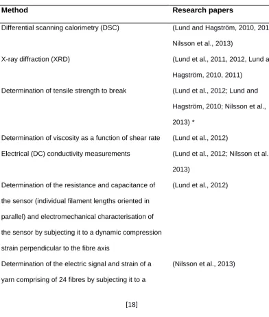
In Sweden research into melt spun piezoelectric textile fibres has resulted in a
patent (Hagström et al., 2014) and a number or research papers. The first paper,
chronologically, by Lund and Hagström (2010), investigated the influence of
spinning parameters on the β-phase crystallinity of PVDF yarns with no additives
or conductive cores. Beginning with the next paper again by Lund and Hagström
(2011) the researchers introduced the concept of bicomponent PVDF fibres (i.e.
PVDF filaments with a conductive core). The conductive cores used in the
research originating in Sweden included electrically conductive composites of
carbon black (CB) and high-density polyethylene (HDPE) (Lund and Hagström,
2011; Nilsson et al., 2013), either non-functionalized or amino-functionalized
[18]
copolymer and CB or a high-density polyethylene and again CB (Lund et al., 2012).
Guo et al. (2013) carried out a comparison between three compositions of
piezoelectric fibres based on PVDF, i.e. PVDF fibres, PVDF/ nanoclay fibres and
PVDF/NH2-DWCNT (amino modified double wall carbon nanotubes). Finally, in a
paper by Nilsson et al. (2014) the composition of fibres under investigation is given
as bicomponent with a PVDF sheath and a conductive core while pointing at a
previous paper (Lund and Hagström, 2011) for more information. Concerning the
methods used for characterisation of the fibres (filaments) examined in the above
papers these are as follows.
Table 1. Characterisation methods used in research papers originating in Sweden
Method Research papers
Differential scanning calorimetry (DSC) (Lund and Hagström, 2010, 2011; Nilsson et al., 2013)
X-ray diffraction (XRD) (Lund et al., 2011, 2012, Lund and Hagström, 2010, 2011)
Determination of tensile strength to break (Lund et al., 2012; Lund and Hagström, 2010; Nilsson et al., 2013) *
Determination of viscosity as a function of shear rate (Lund et al., 2012)
Electrical (DC) conductivity measurements (Lund et al., 2012; Nilsson et al., 2013)
Determination of the resistance and capacitance of
the sensor (individual filament lengths oriented in
parallel) and electromechanical characterisation of
the sensor by subjecting it to a dynamic compression
strain perpendicular to the fibre axis
(Lund et al., 2012)
Determination of the electric signal and strain of a
yarn comprising of 24 fibres by subjecting it to a
[19] dynamic tensile strain parallel to the fibre/ yarn axis
and estimations of the mean power from the fibres
Evaluation of the sensor (yarn woven into fabric)
properties for heartbeat detection
(Nilsson et al., 2013)
Characterisation of the piezoelectric fibres by
connecting the fibre to an impedance analyser.
(Nilsson et al., 2014)
*testing carried in yarn form
Regarding the research originating in the UK; in 2011, Vatansever et al (2011),
published a chapter in the book “Smart Woven Fabrics in Renewable Energy
Generation” and the chapter included a presentation of the production method for
PVDF piezoelectric monofilament yarns. In 2012, Vatasnaver et al, (2012a)
presented the production process of a PA-11 (Polyamide 11) piezoelectric
monofilament yarn. Vatansaver et al. (2011) and Hadimani et al. (2013),
investigated the properties of a PVDF monofilament yarn. In 2015 Bayramol et al.
(2015), investigated the effect of addition of multiwalled carbon nanotubes on the
piezoelectric properties of polypropylene filaments.
The UK based research constitutes the only research that investigated materials
other than PVDF, namely PA-11 (Vatansever et al., 2012a)and Polypropylene
(Bayramol et al., 2015). They also hold the oldest patent (Siores et al., 2010)on
the production of piezoelectric melt-spun textile filaments, the process described
in detail by Hadimani et al. (2013). Vatensever et al. (Vatansever et al., 2012a)
touches on the subject of the amount of energy produced by a single filament vs
the energy required for powering small electronic devises, though without
[20]
Table 2. Characterisation methods used in research papers originating in the UK
Method Research papers
Fourier transform infrared spectroscopy (FTIR) (Hadimani et al., 2013)
X-ray powder diffraction (XRD) (Hadimani et al., 2013)
Determination of linear density (Hadimani et al., 2013; D. Vatansever et al., 2011)
Determination of tensile strength (Bayramol et al., 2015; D. Vatansever et al., 2011)
Examination of the micro structures of the filaments
under scanning electron microscope (SEM)
(Bayramol et al., 2015; Hadimani et al., 2013; D. Vatansever et al., 2011)
Determination of the electric response in Volts of a
group of fibres when stimulated by a mechanical
stimulus (impact)
(Bayramol et al., 2015;
Derman Vatansever et al.,
2011; D. Vatansever et al.,
2011; Vatansever et al.,
2012a)
In Germany, in 2010, Walter et al (2010) manufactured melt-spun PVDF fibres of
textile finesse. Apart from the typical production processes, the produced filaments
underwent false twist texturizing. In 2011 Steinmann et al. (2011), produced
melt-spun PVDF textile fibres using different production parameters. Also in 2011,
Walter et al (2011) carried out characterisation of composites made by combining
piezoelectric PVDF monofilaments with a two-composite epoxy resin. In 2012,
Walter et al (2012) further developed the previous research project (Walter et al.,
2010)by producing both a warp knitted fabric and two woven fabrics (plain and twill
weave). In 2013 Glauß et al (2013), investigated the spinability and characteristics
of PVDF bicomponent fibres with CNT/ PP core. This research project related to
research done by Steinmann et al (2013) on the extrusion of CNT-modified
polymers. In 2015 Glauß et al (2015) worked on the production and functionalizing
[21]
Also in 2015 Glauß et al (2015)presented their research in the 4th International
Conference on Materials and Applications for Sensors and Transducers. The
presentation regarded the poling effect on bicomponent piezoelectric fibres (PVDF
sheath with carbon nanotubes core).
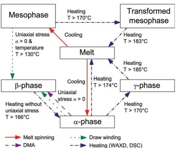
The research by Steinmann et al. (2011) into the phase transitions of melt-spun
PVDF fibres was a significant step in determining the effect of process parameters
on the crystallinity of PVDF. The aim of the research was to understand the
crystallization and phase transitions in PVDF fibres in order optimize the formation
of the β phase (which is connected to the piezoelectric behavior of PVDF). The
research resulted in a detailed overview of the effect of production properties on
the phase transformations of PVDF, which can be seen in summary in Figure 4.
[22]
Walter et al. (2011) constructed composite specimens using a sandwich of PVDF
monofilaments placed parallel to each other and an epoxy resin, placed between
copper films. Polarization was carried out on the composite specimens in an oil
bath. Determination of the piezoelectric behaviour of the samples was carried out
both parallel and perpendicular to the fibres. The specimens were subjected to
tensile strain and the voltage produced was measured. The results showed an
anisotropy of the behaviour of the composite specimen regarding the voltage
produced depending on the direction of the strain (lengthwise or perpendicular to
the length).
Table 3. Characterisation methods used in research papers originating in Germany
Method Research papers
Differential scanning calorimetry (DSC) (Steinmann et al., 2011,
2013, Walter et al., 2010,
2011)
Wide angle, x-ray diffraction (XRD) (Steinmann et al., 2011,
2013, Walter et al., 2010,
2011)
Scanning electron microscope SEM (Walter et al., 2010)
Determination of yarn finesse (Walter et al., 2010)
Determination of tensile strength at break (Walter et al., 2010, 2011)
Determination of hot air shrinkage (Walter et al., 2010)
Dynamic mechanical analysis (DMA) (Steinmann et al., 2011)
Monitoring of the formation of surface charges on the
composites under tensile and bending deformation
(Walter et al., 2011)
Rheometry measurements (Steinmann et al., 2013)
[23]
Determination of specific resistivity (B. Glauß et al., 2015; Steinmann et al., 2013)
Bright field microscopy (Steinmann et al., 2013)
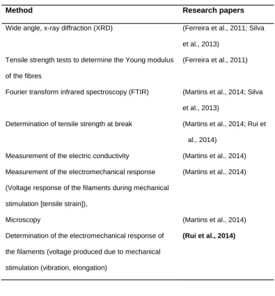
In Portugal, in 2011, Ferreira et al (2011) investigated the effect of processing
conditions and a conductive inner core on the electroactive phase content and the
mechanical properties of PVDF filaments without a core and with a core containing
a conductive PP (polypropylene)/Carbon black composite. In 2013 Silva et al
(2013) investigated the effect of repeated processing cycles on crystallinity and
electroactive phase content of recycled PVDF filaments. In 2014 Martins et al
(2014) examined the properties of piezoelectric coaxial filaments. The test
specimens comprised of a piezoelectric cable obtained from a two-layer
coextruded filament, comprising an internal semi conductive electrode
(carbon-black filled polypropylene compound and a carbon nanotube-based compound)
and a PVDF layer, coated with a thin layer of a semi conductive copper-based
lacquer. Also in Portugal, in 2014, Rui et al. (2014) investigated coaxial PVDF
filaments with a filament core comprising of conductive PP. Ferreira et al. (2011)
concentrated their efforts in producing coaxial piezoelectric filaments made from
PVDF, as opposed to pure polymer filaments. The use of a conductive PP/carbon
black composite core in the filaments is a common approach in other research for
instance the work by researchers based in Sweden (Guo et al., 2013; Lund et al.,
2011, 2012, Nilsson et al., 2013, 2014) and in Germany (Glauß et al., 2013;
Benjamin Glauß et al., 2015; B. Glauß et al., 2015).
The subject of the research by Silva et al. (2013) (recycled PVDF filaments) was
unique in the literature reviewed. The results of several consecutive processing
[24]
studied were unaffected or only very slightly affected by up to 9 processing cycles
suggesting that PVDF recycling was feasible regarding its electroactive properties.
Table 4. Characterisation methods used in research papers originating in Portugal
Method Research papers
Wide angle, x-ray diffraction (XRD) (Ferreira et al., 2011; Silva et al., 2013)
Tensile strength tests to determine the Young modulus
of the fibres
(Ferreira et al., 2011)
Fourier transform infrared spectroscopy (FTIR) (Martins et al., 2014; Silva et al., 2013)
Determination of tensile strength at break (Martins et al., 2014; Rui et al., 2014)
Measurement of the electric conductivity (Martins et al., 2014)
Measurement of the electromechanical response
(Voltage response of the filaments during mechanical
stimulation [tensile strain]),
(Martins et al., 2014)
Microscopy (Martins et al., 2014)
Determination of the electromechanical response of
the filaments (voltage produced due to mechanical
stimulation (vibration, elongation)
(Rui et al., 2014)
In France, Kechiche et al. (2013) investigated the properties of a piezoelectric
coaxial filament, which had a sheath of P(VDF70-TrFE30)
(poly(vinylidenefluoride-trifluoroethylene)) and a copper monofilament as core. Their work was based on
previous research carried out by Khoffi et al (2011) on the production of a
[25]
In a joint paper by researchers based in Australia and Germany, Magniez et al.
(2013) investigated the effect of drawing on the molecular orientation and
polymorphism of melt-spun PVDF fibres. The methods used for the
characterisation of the fibres were, i) determination of tensile properties of the
fibres, ii) XRD, iii) FTIR, iv) determination of molecular orientation using optical
birefringence, v) determination of the electric response (Voltage) of the
piezoelectric fibres integrated in to a woven textile structure after mechanical
stimulation (compression).
The approach by Kechiche et al. (2013) of manufacturing and studying a coaxial
filament(PET/copper) was found to be innovative in the literature reviewed. The
research team had to design and develop, a new type spinneret to provide a good
centring of the inner core(copper filament) in the P(VDF70-TrFE30) matrix
copolymer. The research team were able to integrate the monofilament yarns into
a woven fabric structure and use the resultant fabric as a pressure sensor.
Table 5. Characterisation methods used in research papers originating in France/ joint paper from Australia & Germany
Method Research papers
Differential scanning calorimetry (DSC) (Khoffi et al., 2011)
Wide angle, x-ray diffraction (XRD) (Khoffi et al., 2011; Magniez et al., 2013)
Fourier transform infrared spectroscopy (FTIR) (Magniez et al., 2013)
Determination of tensile strength (Khoffi et al., 2011; Magniez et al., 2013)
Determination of the sensing capabilities of a woven
fabric incorporating the coaxial filaments (voltage
response to compression)
(Khoffi et al., 2011)
Determination of molecular orientation using optical
birefringence
[26]
Determination of the electric response (Voltage) of
the piezoelectric fibres integrated in to a woven
textile structure after mechanical stimulation
(compression)
(Magniez et al., 2013)
In 2012 Vassiliadis et al. (2012)measured the electric properties, of certain
piezoelectric fibres, namely, PVDF, PP and PA-11, when stimulated mechanically
by a peg fixed on a shaft with a varied speed of rotation. The measurements taken
using this experimental set up, included the peak to peak voltage produced by the
fibres under that varied stimuli. In 2013 Vossou et al (2013) carried out a
computational investigation of the mechanical behaviour the same piezoelectric
fibres as Vassiliadis et al. (2012). In that paper, modal analysis of a piezoelectric
fibre was performed with the use of the finite elements method to evaluate its
eigenfrequencies and mode shapes (modal analysis is the study of the dynamic
properties of systems in the frequency domain; a typical example would be testing
structures under vibrational excitation).
Furthermore, by comparing the diagram produced by plotting the bending, y-axis,
reaction moment, developed at the clamped end of the fibres versus time to the
diagram of the deflection of the free end of the fibres it was found that the diagram
of the bending, y-axis, reaction moment resembled strongly the typical waveform
produced during periodic stimulation of piezoelectric ribbon fibres plotting voltage
versus time. These findings suggest that the production of electric power through
the stimulation of the fibres is confined to the clamped area of the fibre i.e. the
[27]
2.3.1 Results of the review of the research into piezoelectric textile fibres
Based on the analysis of the published literature that pertains to melt–spun
piezoelectric textile fibres three conclusions can be reached i) most of the research
carried out focuses on PVDF core spun fibres with very few exceptions for example
the 2015 paper by Bayramol et al. (2015) that investigated the piezoelectric
behaviour of PP, ii) the majority of the current research utilizes test methods such
as XRD, DSC and FTIR to characterise piezoelectric fibres and iii) there is no
standardized method for the determination of the electrical response of the fibres
to mechanical stimulation (neither as a method nor as equipment). Methods such
as XRD, DSC and FTIR aim at characterisation of the fibre crystallinity and
especially in the case of PVDF, the percentage of β phase, which is the source of
the piezoelectric properties for polymers.
Furthermore, regarding the characterisation of the electromechanical response of
the fibres, the data offered by the literature can be summarised by noting that
there are two approaches a) testing that is intended to show the potential of the
fibres, i.e. qualitative tests and b) testing that measures the voltage produced by
the fibres when the fibres (or multifilament yarns or fabrics incorporating said
yarns) are mechanically stimulated either by tensile strain (Martins et al., 2014;
Nilsson et al., 2013; Rui et al., 2014), impact (D. Vatansever et al., 2011;
Vatansever et al., 2012a; Walter et al., 2011) or compression (Khoffi et al., 2011;
Lund et al., 2012; Magniez et al., 2013).
From the electrical point of view, the previous research approaches reported in
the cited literature restrict themselves in the measurement of the generated
voltage, i.e. the various piezoelectric fibres were characterized by the maximum
voltage generated. In most of the tests reported in the existing literature the
[28]
load was presented. In most cases this open circuit voltage becomes the main
performance indication and ranking criterion.
However, just the open circuit voltage does not allow the full study of the
piezoelectric fibre as an electrical generator i.e. it is impossible to assess the
current provided by the source under operation conditions with load connected.
Consequently, using only, the open circuit voltage it is impossible to estimate the
true electrical power produced by the piezoelectric fibre. Furthermore, measuring
both the voltage and the current generated by the specimens it can be discerned
that the capacitance behaviour of the materials aka the phase difference between
voltage and current measurements.
2.4 Textile-element based capacitors
The current trend for overcoming the difficulties inherent to the integration of
electronic components into textile substrates involves the development and
replacement of traditional electronic components by textile based materials and
structures, such as conductive textiles (Balint et al., 2014; Chen et al., 2011; Das
and Prusty, 2012; Park et al., 2012; Park and Jayaraman, 2003; Shirakawa et al.,
1977), textile based light emitting diodes (LED) (Yang et al., 2012), transistors
(Hamedi et al., 2007; Małachowski and Żmija, 2010), and sensors (Ma et al.,
2014; Takamatsu et al., 2012).
There have been various attempts at constructing textile-based capacitors many
of them attempting to create structures corresponding to the classical parallel
plate ones. Sergio et al. (2002) described a sensor array manufactured by
alternating rows and columns of isolating and conductive fibres. While the
[29]
array, the scenario that was realized comprised capacitors that are implemented
as strips of conductive fabric thermally soldered to the two opposite sides of a
foam layer. Meyer et al. (2006)presented an array of textile capacitors, where the
plates were separated by a spacer insert – the actual plates of the capacitors were
created by embroidering with conductive thread on the fabric that formed the outer
layer of the combined structure and a method for measuring muscle activity by a
sensor employing two layers of spacer fabric sandwiched between two layers of
conductive fabric. Eriksson et al. (2011) investigated the concept of a 3D-woven
capacitive structure as a proof of concept (the woven prototype capacitor was
supported between Plexiglas plates).
In the research by Yang et al. (2014)the capacitor effect was produced by silver
yarn fabric that was stitched on synthetic fibre fabric and placed on a foam pad
that was shaped like a prism. The combined structure was then sewn on an elastic
band. The sensor was modelled as a breath sensing system. Guo et. al
(2016)researched a capacitive tactile sensor (e-skin) based on a carbon black
(CB)/silicone rubber (SR) composite dielectric printed on a flexible textile
substrate (Polypropylene (PP) non-woven fabric), that was then covered in
rubber. The design was based on screen printing of the composite dielectric on a
textile substrate, to provide flexibility and wearing comfort.
Takamatsu et al. (2016) in their research trying to develop a sensing floor covering
(meter-scale) with the proposed use of monitoring movement of humans
(specifically the elderly) across floors, created a specialised woven structure
incorporating capacitors created by overlapping wide width stripes of polyamide
yarns PA, individually coated with conductive polymer of
poly(3,4-ethylenedioxythiophene): poly(styrene sulfonate) (PEDOT:PSS). The overlap of
the stripes was in two layers at right angles creating a grid with sensor capabilities
[30]
Wijesiriwardana et al (2005) used flatbed knitting and conductive polymer yarns
made from Copper Sulphide (CuS) polyester to construct capacitive fibre-meshed
transducers that can be used for touch sensing. Furthermore, they constructed
two sensors with electrode islands with knitted structures. The first one was
constructed with parallel-plate arrangement, and it was used as a touch and
compression transducer. The second one was constructed with a single-layer
electrode structure and it was used as a near-field proximity sensor. For the
double-layer approach, an elastic nonconductive material was used between the
electrodes. Each layer was constructed separately. Wijesiriwardana suggested
that the layers could be assembled by using laminating or sewing; for the
prototypes presented in the specific paper sewing had been used.
Avloni et al (2008) investigated the electromagnetic interference shielding
effectiveness of polypyrrole-coated polyester nonwoven textiles. The research
was carried out on four non-woven samples and one twill fabric sample. A
correlation between the shielding effectiveness and the surface conductivity of
composites was found.
Holleczek et al. (2010) investigated and developed textile pressure sensors for
sports applications. Electrodes of conductive textiles coated with silver arranged
on both sides of compressible spacers made from Croslite ™ integrated three
sensors into a snowboarding sock at relevant positions under the heel and the
ball of the foot were used to form a capacitor. Three sensors were integrated into
a snowboarding sock at relevant positions under the heel and the ball of the foot.
The pressure measurement results were processed using a Nearest Centroid
Classifier algorithm (NCC). After processing the results showed that the system
could be used for gait analysis or the monitoring of the in-shoe pressure
[31]
Meyer et al (2010), developed a textile pressure sensor for sitting posture
classification. The pressure sensor comprised of two electrodes made of
conductive textile, with a compressible spacer (3D warp knitted fabric) to separate
them. The electrodes on one side of the sensor were single electrodes which were
embroidered with conductive yarn. On the other side of the sensor there was the
common electrode which consisted of a silver-coated woven textile. Most recently
Potirakis et al. (2017) patented a method to produce textile capacitors by hot
welding.
The challenges faced when creating a textile-based capacitor as presented in the
literature are concerned with the need i) for a structure with easily customizable
construction parameters and relative structural stability, and ii) the availability of
a production method that should preferably not require expensive or complicated
steps. A very common approach to constructing a 3D structure mimicking the
conventional parallel plate capacitor as presented in the literature was the
positioning of the conducting elements (whether fabric or composite material)
against foam or 3D textile structures as an external (added element). This resulted
in structures that were complex and not easily customizable and allowed lateral