178
Copyright © 2016. Vandana Publications. All Rights Reserved.
Volume-6, Issue-6, November-December 2016
International Journal of Engineering and Management Research
Page Number: 178-184
Investigation and Analysis of Turning Tool (High Manganese Steel)
using Finite Element Method
M.Rajesh1, V.Siva Prasad2, Dr. G.Nagamalleswa Rao3
1,2
Assistant Professor, Department of Mechanical Engineering, GATES Institute of Technology, Gooty, AP, INDIA
3Principal & Professor, Department of Mechanical Engineering, GATES Institute of Technology, Gooty, AP, INDIA
ABSTRACT
There is a need for materials of high hardness and resistance to cutting. As we know the machining of these materials has always been a great challenge. Machining of these alloys and materials required for cutting high-strength, which sometimes is not economical and sometimes even impractical. And even the non-conventional processes are generally limited to the point of view of productivity. The advantages of easy component manufacturing of excessive hard materials can be substantial in terms of reducing costs and lead times machined compared to the traditional one involves the heat treatment, grinding and manual finishing / polishing. In the hot working at a temperature of work piece is increased so as to reduce its shear strength. This paper will focus on hot working and analysis of High Manganese Steel with petroleum fuel. Several parameters, such as cutting speed, feed, depth of cut and the temperature of the work piece are taken. An experiment was conducted. Even the machining process was simulated in ANSYS to find corresponding deformation, rate of tool wear, cutting force and the temperature distribution.
Keywords--- Cutting speed, feed, depth of cut and hot machining, non-conventional processes, FEM, tool wear, turning operation
I.
INTRODUCTION
When the technology of mass production began with the transfer lines from Henry Ford, there came into being the fundamental techniques of working. Any working consumes throughout the world a large amount of money every year. A lot of material is wasted as scrap or chip formation [1]. Machinability has received much attention from researchers. One of the main objectives of the process is the production of materials more economically. A wrong decision can result in expensive production costs and reduces the quality of product [2].Many manufacturing processes involve some aspects of the operations of cutting, in which there is the need to
estimate quantitatively the technological performance of machining operations such as tool life, strength, power and surface finish. This information is necessary for the performance of the selection and design of machine tools and cutting tools, as well as the optimization of cutting conditions for the efficient and effective operations. The most important factor for the successful continuation of production in a typical operation is the wear of cutting tools in metal. The production of exotic materials and intelligent materials has become very essential to meet the strength requirements for the aerospace and defense industry [3]. These materials are used in the production of
components for electrical, chemical, dental
orthopaedics, nuclear and aerospace industries, where high dimensional accuracy, tool life and surface roughness of a satisfactory quality [4]. Non-conventional machining process, other practicable means, is mostly limited to low scale removal of material. For the removal of bulk material, the growing interest in the process of hot working is being developed in the industry. In this method, the work piece is softened by heating and consequently the cutting force is reduced [5].
1.1 Machining Operation
Machining operation is a machining method conducted on conventional machine tools in which work piece is preheated before cutting operation to become softer and thereby to reduce its shear strength. The high operating temperature in hot turning process imparts softness on the material under investigation, which eases the machining process and further reduces the high cost of changing and sharpening cutting tools.
179
Copyright © 2016. Vandana Publications. All Rights Reserved.
1.2 MaterialsThe materials which are generally machined by hot machining operation are hardened steel, High Manganese steel, NH4 (Ni-hard steel), Superalloys, High Chromium white CI, Ceramic Materials, Hyperchrome CI alloys, Cr-Mo white CI, Stainless Steel, S-816 alloy, X-alloy, Timken 16-25-6, Navy Grade Steel, Inconel-X, Ni-Cr Steel and alloys of tungsten, molybdenum, titanium and tantalum.
1.3 Heating Methods
The various ways of preheating of the work piece to heat are:
Furnace Heating
Resistance Heating
Flame Heating (oxy-acetylene, oxy-LPG)
Arc Heating
Plasma Arc Heating
Induction Heating
Laser Assisted Heating
Radio Frequency Heating Apparatus
1.4 Basic Requirements and Precautions of Heating the Work piece
• Heat applied should be localized in the cutting zone that is just in front of the cutting edge, where the deformation of the workpiece material is maximum.
• Heating should be limited to a small area thus limiting expansion of work piece, so that the dimensional accuracy can be tolerated.
• The method of supply of heat should be such that the limitations imposed by the size and shape of the workpiece, and machining conditions are minimal.
• Machined surfaces must not be contaminated or
overheated, resulting in metallurgical changes that can produce distortion to the uncut material.
• The heat source must be able to provide a great contribution to specific heat to create a rapid response to temperature in front of the tool.
• The heating system used must be low initial investment and operation and maintenance.
• Safety should be given priority and is absolutely essential that the method used is not dangerous for the operator.
• The temperature control device must have high degree of accuracy.
II.
FINITE ELEMENT ANALYSIS
2.1 Introduction to Finite Element Analysis
FEA consists of a computer model of a material or design that is stressed and analyzed for specific results. It is used in the design of new products, and refinement of the existing product. A company is able to verify a proposed design and will be able to perform the specification of the client before fabrication or construction. Modifying an existing product or structure is used to qualify the product or structure of a new condition of service. In the case of structural failure, FEA may be used to help determine the design modifications to meet the new condition. There are generally two types of analysis that are used in the industry: 2-D modeling, and
3-D modeling. While 2-D modeling conserves simplicity and allows the analysis to be performed on a relatively normal computer, it tends to give less accurate results. 3-D modeling, however, it produces more accurate results sacrificing the ability to run on all computers faster, but actually [6].
2.2 Steps Required for Modeling and simulating a Turning process
2.2.1 Process setup and conditions
Before modeling and simulation, the user must
set the starting data, i.e. the parameters and process conditions: cutting speed, depth of cut, feed rate, the ambient temperature, if a cooling liquid will be present or not and coefficient of friction. These parameters will be described and set in the first step, pre-processor. When setting the conditions of the process, the user must choose the ambient temperature, coolant with the convection coefficient, friction factor and cutting heat transfer coefficient.
2.2.2 Tool and work piece set
For the configuration tool, the user has two options. First, the user can choose the geometry of the tool from the libraries of software tools. Second, if the tool geometry is complex, such as a drill or a milling insert, this can be imported from CAD systems. There should not an area without free edges, no corners are not valid and invalid guidelines.
2.2.3 Boundary conditions
The boundary conditions help the user to determine the interaction of the piece with other objects in the simulation. The boundary conditions are most often used: heat exchange with the environment and the speed in contact between objects in the model, etc.
2.2.4 Tool and work piece material
A material should be assigned to the tool and another for the piece. The material can be loaded from the library, starting from aluminum and materials beta up to steel and superalloys, including composites. Most of the tools are made of carbide or toilet. If the user requires a special material, the software gives the possibility to create it. The user needs to know some properties of the material.
2.2.5 Mesh generation
FEM uses Lagrangian or Eulerian meshing criteria. The mesh of Lagrange is reformulated in almost each time step, in order to handle the deformation of the material. If a crash simulation, for any reason, a new simulation can start where the other stopped. The tool and the workpiece meshing are very important for a process simulation accurately. A finer mesh gives a finer granularity. If the number of elements increases, also increases the time. Meshing the piece is much more important. In general, pieces are modeled as objects made of plastic, can be easily deformed and cut by tools. When the mesh deforms, must be frequently regenerated. During the simulation, the mesh helps the reconstruction of distorted material.
2.2.6 Simulation controls and database generation
180
Copyright © 2016. Vandana Publications. All Rights Reserved.
simulation and generation of database. The simulation commands, i.e. the number of simulation steps, step size to save, and calculation tool wear are the latest data pre-processing that needs to be set prior to running the simulation. The tool wear can also be calculated.
The structure and properties of the material affect the cutting forces and therefore the rate of wear. Tool-chip interface means first of all cutting parameters, friction, and coolants, these reducing tool wear and cutting temperature if they are set correctly. the instrument must be appropriately chosen for a transaction subject to the FEM modeling and simulation (turning, drilling, and milling). The optimal performance of a tool, a proper combination between the cutting conditions and the properties of the instruments.
III.
EXPERIMENTAL PROCEDURE
3.1 Experimental Setup
The experiment was conducted on a central lathe. The following figure (3.1) shows the schematic diagram of a central lathe.
3.2 Workpiece
The workpiece comprised of a 500 x 50 mm cylinder made of high manganese steel. The composition, mechanical and physical properties of the high manganese steel work material are given in the following tables.
Table 3.1: Chemical Composition
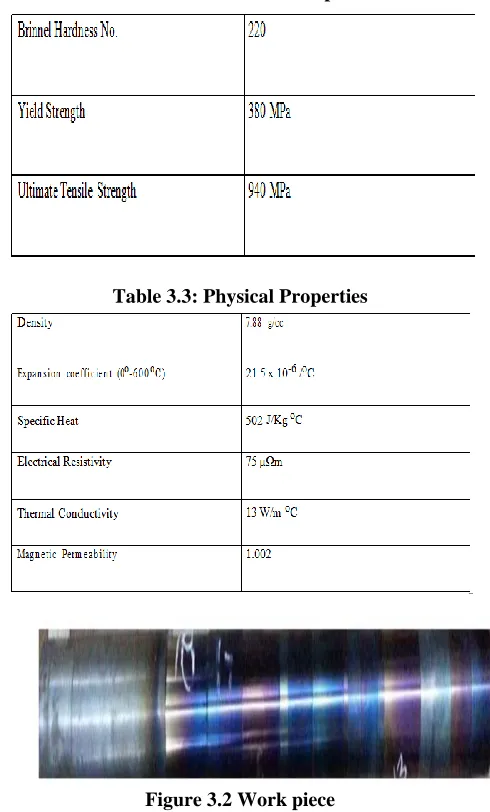
Table 3.2: Mechanical Properties
Table 3.3: Physical Properties
Figure 3.2 Work piece
3.3 Tool
The turning operation was done by SNMG carbide insert.
Fig. 3.3: SNMG Carbide inserts
3.4 Procedure
1. The work piece was mounted between the
181
Copyright © 2016. Vandana Publications. All Rights Reserved.
as to avoid localization of heat. Excessive heating may cause change in metallurgical properties of the work piece material. It may also result in melting of the material.
2. The experiment must be conducted at particular temperatures for different readings. The temperature of the work piece must be maintained upto a particular value for a single run. The work piece must be heated until it reaches the desired temperature. Once it has attained the temperature, heating must be discontinued. Else there will be error in readings.
3. In this experiment automatic heating arrangement was used. The flame torch was mounted on a shaft which was connected to a servo motor. The actual movement of the torch (mounted on the shaft) facilitated the heating and discontinuation of heating of the work piece. A thermocouple was used to measure the temperature of the rotating work piece.
4. A sensor was attached to the thermocouple which was used to convert the analog signal to digital signal for the servo motor. The display panel displayed the temperature at every instant. The desired temperature was set.
3.5 Observation
Heating of the work piece was done using LPG flame. The temperature of the heat affected zone was maintained using automated heating arrangement. The following table 4.4 shows the variation of temperature with increasing distance from the heat affected zone when the temperature maintained is 200oC.
Table 3.4 Variation of temperature and Distance
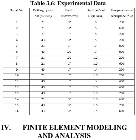
Table 3.6: Experimental Data
IV.
FINITE ELEMENT MODELING
AND ANALYSIS
4.1 Distribution of temperature of work piece:(The analysis is performed using ANSYS 14))
4.1.1 Problem Statement
A cylindrical workpiece of diameter 50 mm and length of 500 mm is rotated in a turning center at 600 rpm. The workpiece is constantly heated with a heat source in movement which is a flame (LPG + O2). We have to design a model in CFD and do analysis to find out the temperature distribution of the workpiece, tool and chip. The temperature of the work piece surface in contact with the flame is varied from 200-600oC.Workpiece material= High manganese steel, Workpiece length= 500 mm, Work piece diameter= 50mm,Rotational speed N= 600 rpm,Flame travel= 0.1 mm/rev,Feed = 0.1 mm/rev
Table 4.1 Chemical Composition of Work piece (High Manganese steel)
Table 4.2 Work material properties
4.1.2 3D Modeling
A cylindrical work piece is modeled in Ansys having the following dimensions. Diameter: 50 mm and Height: 500 mm
4.1.3 Circular cross section
182
Copyright © 2016. Vandana Publications. All Rights Reserved.
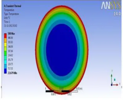
are applied. The surface is meshed by taking element size equal to .25 mm. The element taken is Quad 4 Node 55.
Initial temperature of the material is 220C. A temperature of 5000C is applied on the outer surface for 1 second.
Figure 4.3 Temp Distributions along the Circular Cross Section
4.2 Modeling of Chip Tool Interface
Various input parameters such as cutting velocity, feed and work piece temperature were taken. The output parameters obtained are given below.
a. Temperature of chip tool interface b. Effective strain
c. Effective stress d. Cutting force e. Thrust force f. Tool wear rate
183
Copyright © 2016. Vandana Publications. All Rights Reserved.
V.
RESULTS AND DISCUSSIONS
Temperature distribution of work piece
Here the error rise because the modeling was done by taking the room temperature as 22oC but during the conduction of the experiment the room temperature was above 30oC.
Temperature distribution at the chip tool interface
A Point is considered at the chip tool interface and its values of temp, strain, stress are calculated for different values of cutting speed and temperature (feed and depth of cut remaining same).
VC = 21m/min, 43 m/min, Temp = 200oC, 600oC
, Feed = .05 mm/rev
It can be seen that the temperature of the chip tool interface increases with increase in cutting speed also.
Effective Strain
It can be seen that the effective strain decreases with increase in cutting speed, other parameters remaining same. But for a given cutting speed the effective strain increases with increase in temperature of work piece.
Effective Stress
With increase in temperature the effective stress increases.
Tool Wear Rate and Cutting Forces
It can be observed from the figures of tool wear
that a minute red region representing high tool wear rate is seen on the model where the temperature of the work piece is taken to be 200oC. On increasing the temperature to 600oC this region vanishes. Hence it can be concluded that on increasing the temperature of the work piece the tool wear rate decreases.
Similarly from the Cutting force and thrust force it can be concluded the on increasing the temperature of work piece the cutting forces decrease.
VI.
CONCLUSION
The following conclusions can be made:
• The temperature of the chip tool interface
increases with increase in cutting speed.
• Effective strain decreases with increase in
cutting speed, other parameters remaining same. But for a given cutting speed the effective strain increases with increase in temperature of work piece
• With increase in temperature the effective stress increases
• On increasing the temperature of the work piece
the tool wear rate decreases.
• On increasing the temperature of work piece the
cutting forces decrease.
Machining process can be used for machining hard materials. But there are some shortcomings. The setup with a heating source should be available. Trained personnel should use the flame. Heat should be uniformly distributed throughout the cross section and care should be taken not to overheat the work material as it will change the metallurgical properties.
ACKNOWLEDGMENT
All glory and adoration is to Almighty God, the sustainer of heaven and earth that sustain us till this moment. I wish to thank everyone who had contributed to successful completion of this experiment. I appreciate the Principal of Gates Institute Technology, Gooty. Andhra Pradesh. and finally for his moral and elderly advice, we pray that God Almighty will continue.
REFERENCES
[1] Ezugwu, E. O., Key improvements in the machining of difficult-to-cut aerospace super alloys, International Journal of Machine Tools & Manufacture 45 (2005) 1353–1367.
[2] Tosun Nihat, Ozler Latif, A study of tool life in hot machining using artificial neural networks and regression analysis method, Journal of Materials Processing Technology 124 (2002) 99–104.
[3] Maity, K.P., Swain, P.K., An experimental
investigation of hot-machining to predict tool life, journal of materials processing technology 198 (2008) 344–349. [4] Davami, M., Zadshakoyan, M., Investigation of Tool Temperature and Surface Quality in Hot Machining of Hard-to-Cut Materials, World Academy of Science, Engineering and Technology 22 2008.
[5] Ranganathan, S., Senthilvelan, T., Multi-response optimization of machining parameters in hot turning using grey analysis, Int J Adv Manuf Technol (2011) 56:455– 462.
[6]www.sv.vt.edu/classes/MSE2094_NoteBook/97ClassP roj/num/widas/history
[7] Zouhar, J., Piska M., Modelling the Orthogonal
184
Copyright © 2016. Vandana Publications. All Rights Reserved.
[8] Tugrul Özel and Erol Zeren, Finite Element Method Simulation of Machining of AISI 1045 Steel With A Round Edge Cutting Tool.
[9] Corina et al., 3D FEM Analysis of Cutting Processes, Advances in Visualization, Imaging and Simulation. [10] Komvopoulos, K. and Erpenbeck, S.A. 1991. Finite Element Modeling of Orthogonal Metal Cutting. Trans. ASME J. Eng. Ind. 113: 253-267.
[11] Lin, Z.C. and Lin, S.Y. 1992. A Coupled Finite
Element Model of Thermo-Elastic-Plastic Large
Deformation for Orthogonal Cutting. Journal of Engineering Materials Technology 114(2): 31-48.
[12] Ceretti, E., Fallbohmer, P., Wu, W.T. and Altan, T. 1996. Application of 2D FEM to Chip Formation in Orthogonal Metal Cutting. Journal of Materials and Processing Technology 59: 169-180.
[13] Bil, H., Kilic, S.E. and Tekkaya, A.E. 2004. A
Comparison of Orthogonal Cutting Data from
Experiments with Three Different Finite Element Models.
International Journal of Machine Tools and
Manufacturing 44: 933-944.
[14] Filice, L., Micari, F., Rizutti, S. and Umbrello, D. 2007. A Critical Analysis on the Friction Modelling in Orthogonal Machining. International Journal of Machine Tools and Manufacturing 47: 709-714.
[15] Attanasio, A., Ceretti, E., Rizzuti, S., Umbrello, D. and Micari, F. 2008. 3D Finite Element Analysis of Tool Wear in Machining. CIRP Annals Manufacturing Technology 57: 61-64.