Paper received: 06.11.2007 Paper accepted: 19.12.2007 Strojniški vestnik - Journal of Mechanical Engineering 54(2008)7-8, 521-530
UDC 621.91
The Effects of Cutting Speed and Feed Rate on Bue-Bul
Formation, Cutting Forces and Surface Roughness When
Machining Aa6351 (T6) Alloy
Hasan Gokkaya1 - Ahmet Taskesen2’*
1 Zonguldak Karaelmas Universitesi Safranbolu Meslek Yuksekokulu, Turkey
2 Makine Egt. Bolumu, Teknik Egt. Fakultesi, Gazi Universitesi, Turkey
In this paper, the effects o f machining parameters such as cutting speed and feed rate on BUE, BUL, main cutting force and surface roughness were experimentally investigated. Optimal and critical cutting parameters were determined. It was found that the cutting speed must be selected above 400-500 m/min in order to prevent BUE and BUL formation when machining o f AA6351 (T6) alloy with uncoated carbide inserts. The results o f this study show that the most important parameter affecting main cutting force and surface roughness is feed rate. As a result o f this study, optimum cutting force and optimum fe e d rate were found in order to minimize surface roughness o f the work piece.
© 2008 Journal o f Mechanical Engineering. All rights reserved.
Keywords: machining, built-up edge (BUE), built-up layer (BUL), cutting forces, surface roughness
0 INTRODUCTION
Turning operations constitute major portion o f machining processes. Although most o f the cutting processes are oblique cutting, two different cutting processes such as orthogonal and oblique cutting exist in metal cutting operations. However, since cutting mechanic behavior is two dimensional, generally orthogonal cutting method is used for the determination o f the effects of machining parameters [1] to [3]. In addition to mechanical properties o f work piece; other parameters such as tool rigidity, cutting speed, feed rate, depth o f cut and tool geometry are also important factors for the determination o f ideal machinability behaviors [4] to [6].
Aluminum alloys have been used for many years in the aviation industry. AA6351 alloy whose main alloy elements are Mg and Si, is one o f the most important alloy among 6xxx series and has a natural aging capability. Strength and hardness o f AA6351 alloy can be increased by heat treatment [4],[7] and [8].
Generally AA6351 (T6) alloy is machined by metal removing processes. When aluminum alloys are machined at low cutting speeds, BUE formation occurs on the rake face o f the cutting tool, causing surface roughness (Ra) to increase [4], [9] and [10], Due to low frictional forces on the tool rake face at high cutting speeds, increasing the cutting speed causes the cutting forces to decrease. This case results in a general
elimination of BUE formation causing to improve surface roughness o f the work piece [11]. Sometimes, BUE formation positively affects the surface roughness of the work piece, since BUE formation increases tool nose radius [12],
In this paper, the effects o f machining parameters namely cutting speed ( Vc) and feed rate if) on BUE, BUL, main cutting force (Fc)
and surface roughness (Ra) were investigated. Analysis o f Variance (ANOVA) o f these machining parameters was carried out; and optimal and critical cutting parameters were determined. AA6351 aluminium alloy having T6 heat treatment was machined with uncoated carbide tools using CNC turning machine under dry cutting conditions. Four different cutting speeds (200 m/min, 300 m/min, 400 m/min, 500 m/min), five different feed rates (0.10 mm/rev, 0.15 mm/rev, 0.20 mm/rev, 0.25 mm/rev, 0.30 mm/rev) and a constant depth o f cut were selected.
1 MATERIALS AND METHOD
1.1. Material
In this experimental study, the effects o f machining parameters on BUE-BUL formation, main cutting force and average surface roughness were investigated and a correlation between these parameters was determined. Cutting speed and feed rate were used as machining parameters.
Test specimens used for the experiments were heat treated (T
6
) AA6351 aluminum alloy having 80 mm diameter and 500 mm length. Chemical composition and mechanical properties o f the test specimens are shown in Table 1.Brinell hardness number (BHN) o f the work piece material used in the experiments was 102 BHN. The hardness values o f the specimens were measured by means o f a “Reicherter Brinell” hardness measuring device. Fine machined test specimens having
10
mm depth were prepared for the measurements. The test specimens were measured from outside through the center for10
times and average measured value was used.1.2. Machining Parameters, Cutting Tool and Tool Holder
Turning experiments were carried out at 20±1°C ambient temperature using changeable carbide inserts having CCGT 120404FN-ALU geometry and K10 quality degree. Rake angle and clearance angles o f the cutting tools were 7° and 5°, respectively. The tool holder used for the tests was CSRNR 2525 M12 having 90° approaching angle and agreeable to ISO 5608. Cutting parameters used for the experiments are shown in Table 2. Four different cutting speeds (200 m/min, 300 m/min, 400 m/min, 500 m/min), five
different feed rates suggested by ISO 3685 (0.10 mm/rev, 0.15 mm/rev, 0.20 mm/rev, 0.25 mm/rev, 0.30 mm/rev) and 1.5 mm constant depth o f cut were selected. A total o f 20 experiments according to cutting parameters and machining levels shown in Table 2 were conducted. All turning tests were carried out under continuous dry cutting conditions.
1.3. Machine Tool and Measuring Equipment
All the tests were done with a “JOHNFORD T35” industrial type CNC turning machine having 10 KW power and revolving capability o f 50-3500 rev/min. Kistler 9257B dynamometer was used to measure all cutting forces (Fc, Ff, Fp), where Fc, was the main cutting force, Ft, was the feed force and Fv, was the ploughing force.
M AHR-Perthometer M l measuring
equipment was used to measure surface roughness o f the work piece material. All o f the tests achieved were repeated three times in order to guarantee its precision. In order to m easure surface roughness, c u t-o ff length and sam pling length w ere assum ed to be 0.8 m m and 5.6 mm, respectively. Finally, after each turning test, the tools w ere further observed in a JE O L -JSM 6060 scanning electron m icroscope (SEM ).
Table 1. Chemical and mechanical properties o f AA6351 alloy
a) Chemical composition (% weight)
Si Fe Cu Mn Mg Zn Al
1,03 0,237 0,0723 0,584 0,665 0,003 Balance
b) M echanical properties
Density Elastic modulus
(x l0 0 0 k g /m 3) GPa
Tensile Strength MPa
Elongation %
Hardness BHN
2.7 75 250
20
102
Table 2. Cutting parameters used for the tests
T Cutting speed
Fc (m/min)
Feed rate f (mm/rev)
Depth o f cut ap
(mm) Cutting Tool Tool Holder
1
200
0.10
2
300 0.150.15 Uncoated Carbide
3 400
0.20
CCGT120404FN-4 500 0.25 ALU
5 0.30
The experim ental results were analyzed w ith analysis o f variance (ANOVA), which was used for identifying the factors significantly affecting the perform ance m easures nam ely main cutting force and surface roughness.
2 RESULTS AND DISCUSSION
2.1 BUE and BUL Formation
G enerally, tool life is determ ined by tool w ear in m achining processes. It can be observed from past studies that the wear m echanism w hich operates in the w idest range o f cutting tem peratures is the adhesion m echanism [2]. U sually, adhesion w ear occurs by the direct transfer o f tool particles to the m etallic chips. These particles adhered to the cutting tool face during m achining process are m echanically unstable and, thus, they can be rem oved from the tool surface by the action o f the high strength cutting forces that are produced. The work piece m aterial adheres to the rake face o f the tool in two different forms. The first and m ost known one involves the form ation o f a B uilt-up Edge (BUE) which is the adhesion o f the work piece m aterial to the cutting edge o f the tool. In the second one, the m aterial transferred is poured to w ider areas on the rake face o f the tool, giving rise to the so- called B uilt-up Layer (BUL) [2], Generally, this BUL form ation is seen during the m achining o f ductile m aterials. BUE and BUL regions can be clearly seen in Fig. 1.
Fig. 1. Schematic image o f cutting tool with BUE and BUL
The cutting tool is gradually worn since BUE formation is repeated periodically during metal cutting. It is known that a strong adhesion exists during machining o f aluminum alloys [12], Therefore, BUE and BUL formations must be taken into consideration when machining these aluminum alloys.
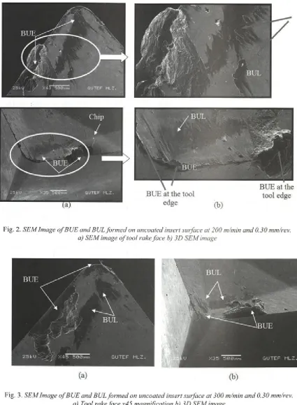
In this part o f the study, four different cutting speeds were used in order to obtain the effects o f cutting speed on BUE and BUL formation, then, SEM images o f BUE-BUL formations were evaluated. Since the highest BUE and BUL formation was observed to SEM Image o f BUE and BUL formed on uncoated insert surface at 200 m/min and 0.30 mm/rev is shown in Fig. 2. occur at the feed rate o f 0.3 mm/rev, this rate was assumed to be the constant feed rate.
It is observed from this figure that, a metal accumulation on the tool surface is associated with the BUL formation and on tool edge with the BUE. It can also be seen from Fig.2 that the major part o f BUE formation occurs at the tool main cutting edge and at the region that chip contacts w ith the air from tool nose through tool holder. This case is connected w ith the temperature at the second deformation region which is called tool-chip interface. Temperature o f tool-chip interface decreases as moving away from tool nose through tool holder [13]. Test results showed that lesser amount o f BUE was form ed close to tool nose. This case can be attributed to less temperature at this region then that o f max BUE region. Past studies claim ed that BUE formation caused tool rake angle to increase [14] to [16]. The experimental results o f this study also agree with the results o f past studies.
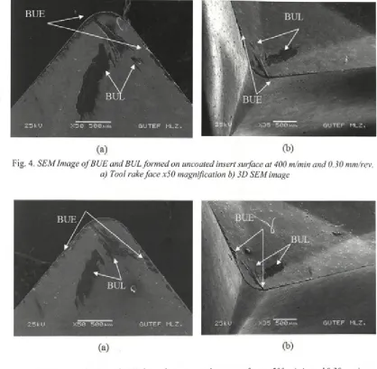
BUE and BUL form ation regions on tool surface at various cutting speeds (300 m/min, 400 m/min and 500 m/min) are depicted in Figs. 3 to 5, respectively.
Fig. 2. SEM Image o f BUE and BUL form ed on uncoated insert surface at 200 m/min and 0.30 mm/rev. a) SEM image o f tool rake face b) 3D SEM image
(a)
(b)
Fig. 4. SEM Image o f BUE and BUL formed on uncoated insert surface at 400 m/min and 0.30 mm/rev. a) Tool rake face x50 magnification b) 3D SEM image
Fig. 5. SEM Image o f BUE and BUL form ed on uncoated insert surface at 500 m/min and 0.30 mm/rev. a) Tool rake face x50 magnification b) 3D SEM image
\
This is caused by temperature increase at second deformation zone since temperature at the second deformation zone increases with cutting speed [
8
]. Fig. 5 shows the BUE-BUL formation at 500 m/min. Comparison o f this figure with Fig. 4 shows a weak increase in BUE-BUL. Test results show that lower cutting speeds (200m/min and 300 m/min) cause greater BUE-BUL formation on tool surface when machining AA6351 alloys. It can be concluded from these results that 400 -500 m/min or higher cutting speeds must be selected in order to prevent BUE-BUL formation.2.2 Cutting Forces and Surface Roughness
2.2.1 Cutting Forces
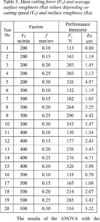
The effects of cutting parameters on main cutting force were evaluated in this part of the study. Main cutting force and surface roughness values determined from the experiments depending on r utting parameters namely cutting speed (Lc) and surface roughness (Ra) are shown in Table 3.
Table 3. Main cutting force (Fc) and average surface roughness (Ra) values depending on cutting speed (Vq) and surface roughness (Ra)
Test Factors
Performance measures
No Vc / Fc Ra
m/min mm/rev N |im
1
200
0.10
113 0.802
200
0.15 163 1.193
200
0.20
203 1.454
200
0.25 303 2.135
200
0.30 326 4.976
3000.10
132 1.197 300 0.15 182 1.85
8
3000.20
264 3.259 300 0.25 290 4.42
10
300 0.30 343 5.4711
4000.10
130 1.5412
400 0.15 177 2.4313 400
0.20
226 3.4314 400 0.25 276 4.71
15 400 0.30 326 5.98
16 500
0.10
118 0.7017 500 0.15 165 1.08
18 500
0.20
214 2.0719 500 0.25 265 3.42
20
500 0.30 316 5.32The results o f the ANOVA with the cutting force are shown in Table 4. This statistical analysis was perform ed for a confidence level o f 95%. F-values shown in Table 4 are the realized significance levels, associated w ith the F-tests for each source o f variation. The sources with a
P-value less than
0.10
are considered to have a statistically significant contribution to the performance measures [17]. Moreover, the last columns o f the Table 4 shows the percent contribution o f each source to the total variation indicating the degree o f influence on the result. Table 4 shows that the only significant factor forthe cutting force Fc is feed rate f which explains 96.6% o f the total variation. It can be concluded from Table 4 that cutting speed Vc having 1.73% significance level does not have a significant contribution to total variation. According to test results, minimum cutting force considering feed rate and cutting speed was determined at
0.10
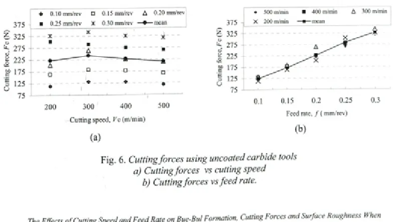
mm/rev and 500 m/min, respectively.M ain cutting forces depending on cutting speed and feed rate determined from experiments are depicted in Fig.
6
. Earlier studies have shown that as cutting speed is made larger, the cutting forces become smaller [1], [5] and [13]. However, the results o f this figure indicate that lower cutting speeds(200
m/min) give lower cutting forces up to a certain cutting speed (300 m/min). It is considered that high temperature at the flow zone and decreasing surface area are the reasons o f this case. Reduction amount in cutting forces depends on work piece material, working conditions and cutting speed ranges. Fig.6
indicates that the relationship between cutting forces and cutting speed is inversely proportional after 300 m/min. BUE and BUL formations cause the tool rake angle to increase and thus, the results o f past studies indicate that increasing the tool rake angle improve the cutting stability and decreases cutting forces [4], [5] and [15]. Experimental results agree with these results. Therefore, BUE and BUL formations are considered to be responsible for this inverse relationship between cutting speed and cutting force, Figs. 2. to 4. Increasing cutting speed for66
.6
% caused cutting force to decrease for 11.15% according to the test results. M aximum cutting force value (343 N) was determined at 300 m/min cutting speed and 0.30 mm/rev when machining AA6351 alloy while minimum cutting force was determined at200
m/min and0.10
mm/rev. According to feed rate, minimum and m aximum main cutting forces were observed at 0.30 mm/rev and 0.10 mm/rev, respectively.Table 4. Analysis o f variance (ANOVA) fo r main cutting force
Source o f Variance SS df Variance F- Value P- Value C (%)
A (VC, m/min) 1947.6 3 649.2 4.16 0.031 1.73
B (f, m/min) 108634.8 4 27158.7 173.87
0
96.60A -B 1874.4
12
156.2 1.67Error
0
0
0
Total 112456.0 19
100
SS: sum o f squeres , df: degree of freedom , C: percent contribution
2.2.2. Surface roughness
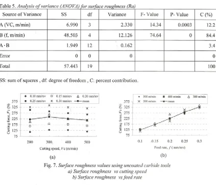
The surface roughness values determined from experiments when machining AA6351 alloy are shown in Table 3. The effects o f cutting speed and feed rate on surface roughness were investigated in this part. The experimental results were analyzed with ANOVA and these results with the surface roughness are shown in Tables 5.
Table 5 shows that the only significant factor for surface roughness Ra is feed rate f, which explains 84.4% o f the total variation. It can be concluded from Table 5 that cutting speed Vc
having
12
.2
% significance level has less contribution to total variation then that o f feed rate. According to test results, minimum surface roughness considering cutting speed and feed rate was determined at200
m/min and0.10
mm/rev, respectively. The test results show that maximumsurface roughness (5.98 pm) was obtained at 400 m/min cutting speed and 0.30 mm/rev feed rate while minimum surface roughness (0.70 pm) was obtained at 500 m/min cutting speed and 0.10 mm/rev feed rate, Table 2. Detailed average surface roughness values versus cutting speed and feed rate are depicted in Fig. 7.
Producing a better surface finish at higher cutting speed is not something unusual in metal cutting, but the conventional explanations are usually related to BUE [17]. That is, the formation o f a built-up-edge is favored in a certain range of cutting speed. By increasing cutting speed beyond this region, BUE will be eliminated and as a result the surface finish will improve [17]. The experimental results show that this cutting speed is above 500 m/min.
375 -
% 325
O
^ 275 fl> S 225 ys
g> 175 -- 125
75 u
♦ 0.10 mm/rev O 0.15 mm/rev A 0.20 mm/rev ■ 0.25 mm/rev X 0.30 mm/rev —» — mean
%
---□
♦
200 300 400
Cutting speed, Vc (m/min)
(a)
500
(b)
Fig.
6
. Cutting forces using uncoated carbide tools a) Cutting forces vs cutting speedTable 5. Analysis o f variance (ANOVA) for surface roughness (Ra)
Source o f Variance SS d f Variance F- Value P- Value C (%)
A (VC, m/min) 6.990 3 2.330 14.34 0.0003
12.2
B (f, m/min) 48.503 4 12.126 74.64
0
84.4A -B 1.949
12
0.162 3.4Error
0
0
0
0
Total 57.443 19
100
SS: sum o f squeres , df: degree o f freedom , C: percent contribution.
Fig. 7. Surface roughness values using uncoated carbide tools a) Surface roughness vs cutting speed
b) Surface roughness vs fe e d rate
It can be concluded from Fig. 7 that depending on the cutting speed, minimum surface
roughness was obtained at
200
m/min.Interestingly, when the cutting speed was increased to 300 m/min, surface roughness also increased. It is considered that larger BUE formations existing on the cutting tool at lower cutting speeds
(200
m/min) caused the tool geometry to change as seen in Fig. 2. Therefore, cutting tool geometry was effected by cutting speed depending on BUE and BUL formation. It was observed from experiment results that BUE formations increased the tool nose radius causing to improve surface roughness. These results agree with some earlier studies [12]. Since less BUE formation exists at the cutting speed o f 400m/min, maximum surface roughness was
determined at this cutting speed. This case can be attributed to a small mount o f BUE formation on tool surface (Fig. 3, initial BUE formation). Previous studies claimed that surface roughness
shows a decrease at higher cutting speeds [5], [10] and [18] to [20]. In agreement with the earlier studies [5], [10], [13] and [18], in the present study, surface roughness gradually decreases after 400 m/min as the cutting speed increases as shown in Fig. 7. The possible reasons o f this case can be explained as high temperature, BUE elimination and high deformation velocity [4] and [16],
therefore be made to the tool users that if the inserts o f
1
mm nose radii are used, feed rates as large as 0.3 mm/rev may be used in order to promote productivity when finishing without significant deterioration in surface roughness [18].3 CONCLUSIONS
The effects o f machining parameters namely cutting speed and feed rate on BUE, BUL, main cutting force and surface roughness were both experimentally and statistically investigated.
BUE and BUL formations caused the tool nose radius and effective rake angle o f cutting tool to increase. BUE was formed at especially low and middle cutting speeds. BUE-BUL formations positively affected the cutting forces and surface roughness at lower cutting speeds. Eligher cutting speeds caused BUE formation to reduce improving machined surface quality.
It was observed from test results that the most important parameter affecting main cutting force FC and surface roughness was the feed rate. Significance level o f these effects was 96.6% for main cutting force and 84.4% for surface roughness. Contribution of cutting speed Vc to total variation was found be more important for surface roughness.
BUE-BUL formations on tool surface at the cutting speeds o f 200 and 300 m/min were found to be larger than those o f 400 and 500 m/m in. Maximum BUE-BUL formation was observed at 200 m/min cutting speed. It was concluded that cutting speed must be selected above 400 - 500 m/min cutting speed in order to prevent BUE and BUL formation.
According to feed rate and cutting speed, maximum cutting force value (343 N) was determined at 300 m/min cutting speed and 0.30 mm/rev when machining AA6351 alloy while minimum cutting force was determined at
200
m/min and0.10
mm/rev.In order to minimize surface roughness, optimum cutting speed and feed rate were found to be 500 m/min and 0.10 mm/rev, respectively. The test results showed that maximum surface roughness (5.98 pm) was obtained at 400 m/min cutting speed and 0.30 mm/rev feed rate while minimum surface roughness (0.70 pm) was
obtained at 500 m/min cutting speed and 0.10 mm/rev feed rate.
4 REFERENCES
[1] Modem Metal Cutting, Practical Handbook, Sandvik Coroman, Sweden, 1994.
[2] Sanchez-Carrilero, M., Sanchez-Sola, J.M., Gonzalez, J.M., Contreras, J.M., Marcos, M. Cutting Forces Compatibility Based On A Plasticity Model. Application to The Oblique Cutting O f The AA2024 Alloy, Int. J. o f Machi Tools & Manufi 2002, no.42, p.559- 565.
[3] Y. Sahin, Y., Talas Kaldirma Prensipleri 1, Gazi Kitabevi, Ankara, 2003, (In Turkish). [4] Aydin, B., Ozcatalbas, Y. AA2014 (T
6
)Alasiminin Islenebilirlik Ozelliklerine Resici Takim Geometrisinin Etkisi, Makine Tasarimi
ve Imalati Dergisi, 2003, no.5, p.89-95, (in Turkish).
[5] Ozcatalbas, Y. Dusuk Alasimli Celikte Yiginti Talas Olusumunun Isleme Ozelliklerine Etkisi, 8. Uluslar arasi Makine Tasarimi ve Imalat Kongresi, ODTU, 1998, p.25-33 (in Turkish).
[
6
] Trent, E.M. Metal Cutting, Taner Ltd. London, 1988.[7] Etibank Aluminyum Isletmesi Muessesi Mudurlugu Urun Katalogu, (In Turkish), 1995 [
8
] Hong, S.Y., Ding, Y., Jeong, W., Friction andcutting forces in cryogenic machining o f T i- 6A1-4V, Int. J. Machi Tools & Manuf., 2001, no.41, p.2271-2285.
[9] Dae, E.K., Dong, H.H. Experimental Investigation of the Contact Sliding Behaviour o f Metals, J Manufac Sci and Eng, 1998, no. 120, p.395-400.
[10] Jeelani, S., Musail, M. Dependence o f Fatigue Life on the Surface Integrity in the Machining o f 224-T 351 Aluminum Alloy Unlubricated Conditions, J Mater Sci, 1986, no.21, p. 155-
160.
[11] Oishi, K. Mirror Cutting o f Aluminium with Sapphire Tool, J Mater Proc Tech, 1996, no.62, p.331-334.
[13] Altm, A., Gökkaya, H., Nalbant, M. M em e Parametrelerinden Kesme Hizinin Inconel 718 Super Alasimin Islenebilirligine Etkisi, Gazi Universitesi Muhendislik Fakultesi, Muhendislik-Mimarhk Fakultesi Dergisi,
2005, (in Turkish).
[14] Seker, U. Talasli Imalatta Takim Tasarimi Ders Notlari, Gazi Universitesi Fen Bìlimleri Enstitusu Yuksek Lisans Ders Notlari, Ankara, 2000, (in Turkish).
[15] Liew, W.Y.H., Hutchingsand, I.M., Williams, J.A. The Interaction Between Tool M aterial Environment and Process Conditions in the M achining o f Aluminum Alloys, Mach Tech,
(2), 1999, p.286-373.
[16] Gokkaya, H., Sur, G., Dilipak, H. PVD ve CVD Kaplamah Sementit Karbiir Kesici Takim lann izletne Parametrelerine Bagli Olarak Yüzey Pürüzlülügüne Etkisinin
Deneysel Olarak incelenmesi, Z.K.U.
Karabuk Teknik Egitim Fakultesi Teknoloji Dergisi, 2004, no.7, (in Turkish).
[17] Aslan, E., Camuscu, N., Birgoren, B. Design optimization o f cutting parameters when turning hardened AISI 4140 steel (63 HRC) with A1203 + TiCN mixed ceramic tool, Mat Des, 2006, in Press.
[18] Chen, W. Cutting forces and surface finish when machining medium hardness steel using CBN tools, Int J Mach Tools & Manuf, 2000, no.40, p.455-466.
[19] Altin A, Nalbant M, Taskesen A. The effects o f cutting speed on tool wear and tool life when machining Inconel 718 w ith ceramic tools, Mat Des, 2007, no.28, p.2518-2522. [20] Taskesen, A., Altin, A., Nalbant, M. The