Research Journal
Volume 10, No. 32, Dec. 2016, pages 269–274
DOI: 10.12913/22998624/66682 Research Article
APPLICATION OF ANSYS IN TEACHING FEM ON THE EXAMPLE OF
A LOADED MARS ROVER CHASSIS
Małgorzata Łazuka1, Ewa Łazuka2
1 Students’ Space Association, Faculty of Power and Aeronautical Engineering, Warsaw University of Technology, Nowowiejska 24, 00-665 Warsaw, Poland, e-mail: [email protected]
2 Department of Applied Mathematics, Faculty of Fundamentals of Technology, Lublin University of Technology, Nadbystrzycka 38, 20-618 Lublin, Poland, e-mail: [email protected]
ABSTRACT
The aim of the paper is to present the idea of using ANSYS software in teaching en-gineering students the finite element method. ANSYS is an extremely sophisticated engineering tool used in almost every engineering company nowadays. It is intro-duced to almost all engineering students during their studies. Using ANSYS know-ingly requires perfect understanding of the finite element method that is responsible for ANSYS work. This paper presents how this professional software can help stu-dents master FEM. The first part of the paper introduces the finite element method. It also suggests a way of using ANSYS in teaching FEM on the example of a two-dimensional restrained beam calculated in a simple computer program. The second part illustrates the effectiveness of ANSYS with sample FEM analysis of a planetary rover’s chassis and presents basic fuctionalities of ANSYS Workbench Mechanical. Conducted calculations provide useful data about the model’s suitability for its pur-pose and possibility of modifications.
Keywords: ANSYS, FEM, finite element method, numerical analysis, teaching, bending, beam, chassis
INTRODUCTION
Since our technical knowledge has devel
-oped and we have discovered and studied all the laws behind various phenomena, we started facing a growing problem: lack of sufficient computing power to simulate various complex processes with satisfactory accuracy. Therefore, we put a great deal of effort into two possible solutions to this problem: increasing the avail
-able computing power and reducing the compu
-tational complexity of considered issues. This way we led to a rapid and widespread develop
-ment of numerical methods, which enable us to perform calculations and obtain approximate results significantly faster than exact solutions. Numerical methods occured essential in numer
-ous engineering disciplines, i.a. mechanical and structural analysis, in which they are an inte
-gral part of the finite element method (FEM), the most popular method of solving complex problems of mechanics [2, 6]. One of the best and most popular tools for simulating materials’ behaviour is ANSYS, which uses various com
-plex numerical algorithms and FEM. It is an en
-gineering analysis software system used i.a. for performing structural analysis, analysing fluid dynamics and designing electronics [1]. There is a great number of different ANSYS products, which makes the system present in career of al
-most every contemporary engineer. However, what also turns out to be surprisingly effective is teaching finite element method with the use of ANSYS.
The aim of this thesis is to demonstrate how
powerful ANSYS is as an engineering software tool, as well as present the possibility of using ANSYS in teaching future engineers.
USING ANSYS IN TEACHING FEM
FEM is a method of calculating some me
-chanical issues of deformable objects by diving them into small elements properly bound together, called finite elements [4]. This problem of model discretisation is one of the most difficult issues for students to understand in the finite element method. The impacts from the outside are usually known in advance and estimated with large safety factors. Determining the boundary conditions during FEM analysis in sophisticated programs like ANSYS is reduced to the knowledge of con
-straints imposed on the model without worrying about their mathematical form. However, choice of the type and number of finite elements has a great influence on the time needed to get the re
-sults and on their accuracy [6]. Therefore, choos
-ing proper finite elements is a key issue dur-ing such calculations. It is crucial to choose a proper shape of the finite element and number of nodes on each of its edges [8]. The grid must be nei
-ther too dense, so that the calculations end in a reasonable time, nor too rare, so that the results do not differ too much from the exact solution. That is why the best strategy is to use rare grids in parts of the model where the considered vari
-able (stress, magnetic field intensity etc.) will not change its value rapidly and to use dense grids in parts where we expect such changes to occur.
After introducing FEM and its main idea,
principles and requirements theoretically during lectures, next step of teaching it is exploring the algorithm. At this point ANSYS may occur use
-ful – however, only as a model to follow. Namely, an interesting idea is to conduct project classes, during which students will have the opportunity to create their own finite element method algo
-rithm basing on their theoretical knowledge. The used model should not be complex – it ought to be just two-dimensional with simple boundary conditions and discretisation into few finite ele
-ments [3]. In case of structural analysis, an excel
-lent example of such a model can be an ordinary, two-dimensional, restrained beam subjected to bending (presented in Figure 1).
Students shall be able not only to code the FEM algorithm step by step and optimise it, but also experiment with it by changing the prob
-lem’s complexity. This exercise shall demonstrate how much our choice of the grid’s density and type will affect the program running time and the accuracy of the results. In case of such a mini simulation program using FEM, of course the nu
merical algorithms would not be as complex as in the ANSYS applications. Instead, various ba
-sic numerical algorithms well-known to students should be used, e.g. conjugate gradient method, Gauss-Seidel method, Jacobi method or succes
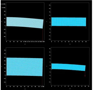
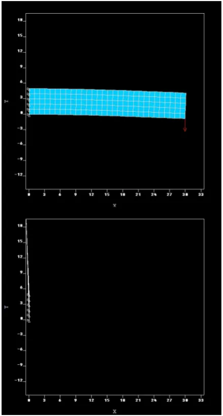
-sive over-relaxation method in order to extend students’ understanding of numerical methods at the same time. For each of alternative algorithms used, it is possible to analyse the calculations and how some variables change with every iteration of the running program. A sample summary of used methods is shown in Figure 2. This exercise perfectly presents the issue of stability of numeri
-cal methods and fixes it in the students’ memory. For example, in Figure 3 it is clearly visible that in another analysed case the Jacobi method is not stable, while successive over-relaxation method provides reasonable results.
When students experience the complexity of FEM by writing their own computer programs, they will most likely use ANSYS more knowing
-ly, with the awareness of all the algorithms used in it that are invisible to the user. Again, during any ANSYS analysis it is possible to visualise the problem of discretisation in a more sophisticated tool. It allows the user to modify the grid exten
-sively and precisely to ensure its perfect adjust
-ment to the needs of conducted simulation. What is more, it provides a rich library of available fi
-nite elements. Therefore, it is possible to consider just one model using different grids again and again and this way demonstrating how sensitive the finite element method algorithm is to changes of the elements.
SAMPLE ANSYS ANALYSIS – MODELING
STRESS AND DEFORMATION OF
A LOADED MARS ROVER CHASSIS
One of the latest innovations of ANSYS worth mentioning is Workbench – a platform designed to integrate various ANSYS applications and this
Fig. 2. Example of information that might be gained during project classes with an exemplary code – comparison of running times and number of iterations
needed for different numerical methods
Fig. 3. Comparison of solutions received after using two different numerical methods for identical beams
and forces – successive over-relaxation method (above) and Jacobi method (below). The divergence
way increase productivity [5]. The platform pro
-vides functionalities of all available products and additionally some basic tools for managing the operations [1]. The platform is exceptionally in
-tuitive thanks to its block diagram visualisation of following steps of the analysis. This chapter pres
-ents a sample analysis of a Mars rover’s chassis with the use of ANSYS Workbench Mechanical, a product for structural analysis which provides simulations of stress, fatigue and heat transfer. Figures presented below show most important steps of such an analysis – discretisation (mesh
-ing) and output solution.
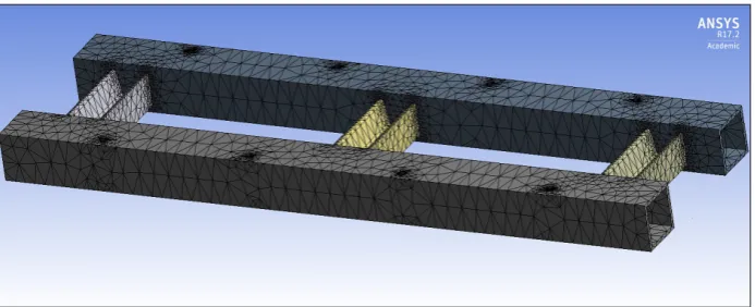
The mesh visible in Figure 4 was condensed in the areas where the chassis shall be integrated with other components of the mobile platform
and where notches occur since these are the areas
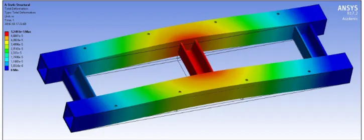
particularly vulnerable to stress concentrations. The analysis contains two different loads. First case is bending the chassis by a force applied on the front wheels. Figure 5 illustrates the equiva
-lent non-Mises stress distribution. The solutions make it possible to predict which areas should be strengthened and where is it possible to place lightening holes or how to modify the design to optimise it, which is often the conclusion of scien
-Fig. 4. Example mesh of a chassis of a Mars rover analog condensed in notch areas where stress concentrations are expected
Fig. 5. Example of ANSYS solution – equivalent non-Mises stress for a force applied on front wheels (on the right)
tific papers [7, 9]. Figure 6 shows the deformation of the frame in this case. As presented, it is pos
-sible to exaggerate the deformed model solution so that the shape of the deformation is clearly vis
-ible. The other case analyses bending by a strong force applied on the centre profile of the frame. This situation (although much weaker) may occur when the mobile platform falls from a high set
-off and components placed inside the chassis fall down. Figure 7 presents the equivalent non-Mises stress and Figure 8 the exaggerated deformation. Another functionality of ANSYS is checking the exact value of stress in any chosen point of the model in order to determine how close it is to the material’s elastic limit. Figures help in conclud
-ing that the frame ought not to have any lighten
-ing holes cut and that the material used should ensure great strength of the welded joints.
CONCLUSIONS
Finite element method became a base, thanks to which sophisticated engineering tools like ANSYS could be developed. It is impossible to imagine contemporary engineering without them.
However, it is possible to reverse the order of this sequence and make ANSYS helpful in finite el
-ement method. It does not have to stimulate its development and improvement, but is a perfect starting point for presenting the relationships between various algorithm parameters and the results in order to make the issue more under
-standable to students and extend the number of ANSYS specialists.
Thanks to this software students will be able to analyse any complex problem and receive clear output solutions as presented in the paper. ANSYS analysis is a vital step in every design
process in order to optimise the design and ensure
safety of the construction.
REFERENCES
1. ANSYS Products. Available: http://www.ansys. com/Products/All-Products [Accessed: 23.09.2016]. 2. Bąk R. and Burczyński T. Strength of materials
with elements of computer application (in Polish). WNT, Warszawa 2001.
3. Górecki B. and Łaniewski-Wołłk Ł. Instructions for Numerical Methods laboratories (in Polish). Division of Aerodynamics, Faculty of Power and Fig. 7. Example of ANSYS solution – equivalent non-Mises stress for a strong force applied on the centre profile
Aeronautical Engineering, Warsaw University of Technology. Available online: https://www.meil. pw.edu.pl/pl/ZA [Accessed: 15.05.2016].
4. Kleiber M. Intruduction to the Finite Element Method (in Polish). IPPT PAN, PWN, Warszawa 1989.
5. Krzesiński G., Zagrajek T., Marek P. and Borkows-ki P. Finite Element Method in mechanics of ma-terials and structural mechanics. Solving sample problems with the use of ANSYS (in Polish). OWPW, 2015.
6. Rakowski G. and Kacprzyk Z. Finite Element Method in structural mechanics (in Polish).
OWPW, 1993.
7. Różyło P. and Wrzesińska K. Numerical analysis of the behavior of compressed thin-walled elements with holes. Advances in Science and Technology Research Journal, 10(31), 2016, 199-206.
8. Rusiński E., Czmochowski J. and Smolnicki T. Advanced Finite Element Method in supporting structures (in Polish). Oficyna Wydawnicza Po-litechniki Wrocławskiej, 1999.