International Journal of Computer Techniques -– Volume 3 Issue 4, July - Aug 2016
ISSN :2394-2231 http://www.ijctjournal.org Page 11
Concepts for the Model-Driven Generation of Graphical Editors in
Eclipse by Using the Graphiti Framework
Markus Gerhart*, Marko Boger**
*(Applied computer science, University of Applied Sciences, Konstanz) ** (Applied computer science, University of Applied Sciences, Konstanz)
---
************************
---Abstract:
Domain-Specific modelling is increasingly adopted in the software development industry. While textual domain specific languages (DSLs) already have a wide impact, graphical DSLs still need to live up to their full potential. In this paper we describe an approach that reduces the time to create a graphical DSL to hours instead of months. The paper describes a generative approach to the creation of graphical editors for the Eclipse platform. A set of carefully designed textual DSLs together with an EMF meta-model are the input for the generator. The output is an Eclipse plugin for a graphical editor for the intended graphical language. The entire project is made available as open source under the name Spray and is being developed by an active community. This paper focuses on the description of the workflow and provides an introduction into the possibilities through this approach of a graphical modelling environment.
Keywords —Domain-Specific-Language (DSL), Model-Driven-Development (MDD), Code Generation, EMF, Xtext, Xtend, Graphiti, Spray, Eclipse IDE, Graphical Editors, Eclipse Plugin
---
************************
---I. INTRODUCTION
Eclipse is one of the focus points of tooling for model driven approaches. Projects like EMF [5], CDO [3] and Xtext [2] are very popular in the domain specific modelling community. But the success of the Eclipse modelling environment is centred around the textual modelling. While the focus of Eclipse or other development environments can play out their textual nature very nicely for this approach, it has long been a difficult environment to build graphical modelling tools. The basic APIs provided by the Eclipse ecosystem, GEF [6] and Draw2D [4], are quite low level and provide no connection to the semantic level of a model. Besides they are quite heavy to use. EMF has often been used for the semantic part, but offers no specific support for graphical modelling. A project that attempted to bridge the gap between GEF and EMF is GMF [7]. It integrates a model driven approach for the development of graphical
modelling tools on the basis of GEF and EMF. But the models to describe the editor proved to be so complex that projects evolved to generate these models from yet higher level models. The generated code of GMF was very complex, hard to understand and extremely difficult to extend for special enhancements. The provided development environment was brittle and cumbersome.
In this paper we present a new generative approach to graphical modelling tools in Eclipse. Instead of using GEF and Draw2D directly, we make use of the relatively new Java framework called Graphiti [8]. Graphiti provides a powerful API, with some lags which will hopefully bit fixed in the near future, to build graphical editors in Eclipse. Internally Graphiti uses GEF and Draw2D but hides the complexity.
However, while it is perfectly possible to develop a graphical modelling tool using Graphiti, we think that the API is very adapt to generate against it from a higher level of abstraction. We
International Journal of Computer Techniques -– Volume 3 Issue 4, July - Aug 2016
ISSN :2394-2231 http://www.ijctjournal.org Page 12 have developed a set of textual modelling languages
to use as input for a generator. The output is Java code for the Graphiti API as well as all other text files needed for the Eclipse plugin mechanism. The result is a graphical modelling tool in Eclipse. With this approach we can reduce the number of lines needed to develop a graphical modelling tool by a factor of about 20. That is, a modelling tool that is developed using Graphiti might require 10.000 lines of code, while our approach generates the needed code from only about 500 lines of textual model descriptions. Thus the cost to develop a graphical modelling tool is reduced by an order of magnitude. The paper first describes the used technologies in chapter II. In chapter III we review related work in the field, mostly other tools and techniques for the generation of modelling tools. Chapter IV describes our general approach for the model driven creation of the modelling editors and the general architecture of our framework. Furthermore, we explain the definition of our own graphical elements with the corresponding DSL and our approach for the flexible styling of these in chapter IV. Chapter V shows an example of a generated graphical editor. Additional we describe in chapter VI the limitations of the presented approach. Chapter VII shows a short evaluation of the presented approach. Finally, we draw conclusions in chapter VIII.
II. BACKGROUND
The used frameworks and libraries are shortly explained in this section. Additionally, a short introduction is given into the used terms.
Model-Driven Engineering (MDE) deals with the automation of software production. This implies that as much as possible artefacts of a software system will be generated form a formal model. (inspired by [9])
Model-Driven Architecture (MDA) is a specific approach of the Object Management Group (OMG) [10], and it describes a model-driven method using their own specified standards (e.g. UML, MOF, XMI).
A Domain Specific Language (DSL) is a formal language, which is exactly tailored to a specific domain, a specific task or problem area.
The Eclipse Modeling Framework (EMF) is a set of plugins for the Eclipse platform. The primarily use is for the model-based code generation.
The Graphical Editing Framework (GEF) is a basic framework of the Eclipse platform with the aim for the creation of graphical editors within Eclipse.
Draw2d is a lightweight set of basic features for the easy displaying of graphical elements.
Graphiti includes EMF and GEF and hides the complication of GEF behind a lightweight and easy to use API.
The Graphical Modeling Project (GMP) provides a set of different plugins for the generative creation of components and runtime infrastructures artefacts for the development of graphical editors with EMF and GEF.
Xtext is an Eclipse Plugin for the development of textual domain-specific languages.
III. RELATED WORK
International Journal of Computer Techniques -– Volume 3 Issue 4, July - Aug 2016
ISSN :2394-2231 http://www.ijctjournal.org Page 13 possible to build a modelling tool in Eclipse. This
paper advocates this approach but it is our observation from experience that this can lead to high and hard to predict development costs. Building such tools directly on GEF and Draw2D provides very little infrastructure support and is accordingly very work intensive. The afore mentioned GMF improves this through a generative approach. However, the DSLs, the generator and the generated code of GMF have themselves high complexities. Extending GMF beyond the default generated behaviour can become particularly painful. A very good alternative to build their own modelling tool in Eclipse is the mentioned framework Graphiti. But it is relatively young and we have no indication on how intensively it is used outside of SAP, who developed the framework. From our experience in this project we can strongly recommend it. The framework hides the complexity of GEF and Draw2D and provides a clearly structured API. However, while the API is well structured and powerful, it naturally lends itself to a generative approach.
During our development, a similar project called IMES [17] is being developed, which pursues a similar approach. The aim of the publicly funded project is to build graphical editors based on Graphiti for functional nets and other systems. The project also uses DSLs and MDD for the generative creation of the graphic editors. Currently the project is not open source and wasn't presented to the public, so it's difficult to compare our approach with the IMES project.
IV. APPROACH
The Spray project includes three different DSLs with the corresponding generators which ends in a plugin for the eclipse platform. As the basic development environment is the eclipse platform used with a number of different plugins. All required downloads are available or referenced on the project home page, together with installation instructions, the user manual and example Projects. The generator is implemented with the Java-like language Xtend [15]. This language specifically developed for the purpose of generating program code. The runtime includes the Graphiti plugin itself and a few extensions of the Graphiti
Framework, which are hopefully integrated into Graphiti over time. The motivation of this paper is on the general approach which is needed to develop a graphical editor. The focus is and not on the generated code or the runtime libraries. The DSLs are implemented using Xtext and based on the approach of [18].
Fig. 1 A Model-Driven approach for Graphical Editors
International Journal of Computer Techniques
ISSN :2394-2231
that are affected by the latest changes in the DSLs and is very efficient.
The Graphical Editor within Eclipse is ready to use as plugin in Eclipse after the generation process The following sections give a short introduction into the three languages.
A. The Spray Core language
At the core provides a graphical editor the ability to create and manipulate objects of a diagram. The resulting object graph is sometimes called model and the structure of the model is defined by a metamodel. The elements of the model are represented by graphical icons that are mentioned in Graphiti as Pictograms.
Spray needs as a base a Ecore metamodel (a requirement that is not part of Graphiti) and describes the mapping of meta-classes on the graphic symbols. Furthermore, it must also be described, which elements can be created in the editor and therefore must be present in the Tool Palette of the Editor.
The basic model of a spray editor is defined the spray main language. The file extension for these models is *.spray and such a file is initially generated by the project wizard. We
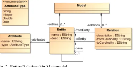
simple Entity / Relationship metamodel (Fig. 2) to develop a small class diagram editor.
Fig. 2 Entity/Relationship Metamodel
In the head of the spray model the diagram type and the E-Class of the root element is initially specified for the diagram (Lis. 1). Optionally, the namespace for the meta-classes can be imported in
1 import domain.*
2 diagram dmodel for Model
International Journal of Computer Techniques -– Volume 3 Issue 4, July - Aug 2016
2231 http://www.ijctjournal.org that are affected by the latest changes in the DSLs
is ready to use after the generation process. The following sections give a short introduction
At the core provides a graphical editor the ability to create and manipulate objects of a diagram. The resulting object graph is sometimes called model and the structure of the model is defined by a e elements of the model are represented by graphical icons that are mentioned in Spray needs as a base a Ecore metamodel (a that is not part of Graphiti) and classes on the it must also be described, which elements can be created in the editor and therefore must be present in the Tool The basic model of a spray editor is defined in the spray main language. The file extension for and such a file is initially izard. We will use a simple Entity / Relationship metamodel (Fig. 2) to
In the head of the spray model the diagram type Class of the root element is initially . Optionally, the can be imported in
order to reduce the use of qualified names in the model.
Lis. 1 Head of a Spray
Afterwards the mapping of meta representation in the editor must context is a distinction needed
which are corresponding to the shapes and which are corresponding to the connections
metamodel the entity is represented by a shape and
the relation between two entities
Listing 2 describes the mapping of an entity to a typical class icon.
Lis. 2 Mapping class to Entity
First, after the keyword class, the type of mapped class (Lis. 2) is provided
path must be specified to an ico the E-Class in the diagram palette.
The actual mapping is defined behind the The spray DSL already enables the basic shapes like rectangles or ellipse icon. The next section describes how
shapes can be created by using a special DSL. A container is a figure that includes other figures and is shown in the standard case
content is established in this case vertically within the container. It consists of a text
a separation line. Underneath is
defined for the attributes in the containment relationship attributes. The graphic elements can define basic styling features such as
filling information. More complex styles
defined by the style DSL, which is described in detail later.
1 class Entity icon "uml/Class.gif" : 2 container (fill=RGB(255,252,223)) 3 {
4 text (bold) “<<Entity>> “+name; 5 line (color=RGB(255,204,51 6 width = 2 );
7 reference attributes; 8 }
Aug 2016
Page 14 order to reduce the use of qualified names in the
mapping of meta-classes to their must be defined. In this needed between types, corresponding to the shapes and which connections. In the used entity is represented by a shape and
between two entities by a connection. Listing 2 describes the mapping of an entity to a
after the keyword class, the type of the is provided. Optionally, a path must be specified to an icon, which represents
alette.
The actual mapping is defined behind the colon. pray DSL already enables the definition of like rectangles or ellipse instead of an section describes how more complex using a special DSL. A container is a figure that includes other figures and n in the standard case as a rectangle. The content is established in this case vertically within text line, followed by Underneath is a compartment for the attributes in the
containment-. The graphic elements can basic styling features such as colour and . More complex styles must be defined by the style DSL, which is described in
1 class Entity icon "uml/Class.gif" : (fill=RGB(255,252,223))
<<Entity>> “+name; 5 line (color=RGB(255,204,51)
International Journal of Computer Techniques
ISSN :2394-2231 Important is the Determination
elements. Not only static strings or a simple of attribute values of the mapped EClass
Arbitrarily complex expressions can be specified, which provides a wide range of possibilities
possible by the integration of the Xtext
expression language Xbase [19]. The tailed Xbase compiler translates the expression into valid Java code, which is executed at the appropriate locations.
Only with this information Spray is able to derive the necessary features for adding new
register them in the feature provider. The following artefacts are created:
Add, update and layout feature for the E Class Entity
Create and add feature for the E attributes for the compartment of t reference entity attributes
Property Sheets for E-Class Entity Attributes
plugin.xml
Important is the plugin.xml because spray generates this file in the src-gen folder
project, which is misleading. The actual plugin.xml is however in the root directory of the project and must be adjusted manually. The reason for this is that it is at any time allowed to make manual changes to this file, but spray cannot know how this should be merge against the generated state.
To create Entities within the editor a behaviour must be indicated inside a behaviour below the Shape Mapping definition (Lis. 3)
Lis. 3 The integrated askFor behaviour
This behaviour definition creates a c
and registers this feature at the feature provider for the Entity. The entity’s which should be generated are thereby inserted into the containment relationship entities of the model object. functionality askFor name causes the opening of an
1 behavior {
2 create into entities "Entität" 3 palette "Neu" askFor name; 4 }
International Journal of Computer Techniques -– Volume 3 Issue 4, July - Aug 2016
2231 http://www.ijctjournal.org of the text
simple access mapped EClass is possible. can be specified, which provides a wide range of possibilities. This is Xtext specific ]. The tailed Xbase compiler translates the expression into valid Java at the appropriate locations. Spray is able to derive new entities and . The following
Add, update and layout feature for the
E-Create and add feature for the E-Class for the compartment of the Class Entity
plugin.xml because spray folder of the . The actual plugin.xml is however in the root directory of the project and must be adjusted manually. The reason for this is that it is at any time allowed to make manual spray cannot know how this
erated state.
the editor a create behaviour area (Lis. 3).
create feature the feature provider for entity’s which should be generated are thereby inserted into the containment s of the model object. The opening of an
input dialogue and creates a new entity and sets the property name of the new entity instance
addition, an entry with the label "entity" in the tool palette in the area "new" applies
Lis. 4 User specific Behaviour
In addition to the create behaviour
specific any own behaviours which are mapped to custom features (Lis. 4).
The identifier openModelElement
derive the class name for this custom feature. Since the implementation of such custom features by the generator cannot be guessed, the specific feature class must be added manually (Lis. 6
custom features are sharable for different classes, so it is also possible to define them as a group outside the class-specific mappings and
reference the custom feature.
Lis. 5 Mapping class to connection definition
To get a complete example it’s necessary to
mapping of the EClass relation. This is represented
create into entities "Entität" palette "Neu" askFor name;
1 behavior { 2 …
3 openModelElement "Open Element 4 }
1 class Relation icon 2 "uml/Extension.gif": 3 connection ( ) { 4 from fromEntity; 5 to toEntity;
6 fromText text ( ) 7 {fromCardinality}; 8 toText text ( ) 9 {toCardinality};
10 connectionText text ( ) 11 {description};
12 }
13 behavior {
14 create into relations "Beziehung" 15 palette "Neu";
16 }
Fig. 3 Example usage of the behaviour
Aug 2016
Page 15 a new entity and sets the the new entity instance (Fig. 3). In addition, an entry with the label "entity" in the tool
area "new" applies.
ehaviour the user can which are mapped to
openModelElement is used to custom feature. Since the implementation of such custom features by the be guessed, the specific feature must be added manually (Lis. 6). Some r different classes, so it is also possible to define them as a group outside specific mappings and each class only
it’s necessary to insert a . This is represented
Open Element";
2 "uml/Extension.gif":
7 {fromCardinality};
10 connectionText text ( )
14 create into relations "Beziehung"
International Journal of Computer Techniques
ISSN :2394-2231
by a connection, which is given as a shape of the type connection (Lis. 5).
The information from (source) and to used to define the references of the EClass
In addition, the text outputs can be specified on both ends and in the centre of the
wherein Xbase expressions can be used again With this minimal information (the model currently covers about 50 lines of code!) possible to create a functional graphical editor with the abilities to create entities, attributes and relations. The properties can be edited via the generated Property Sheets.
The generated classes of the editor must be adjusted with a high probability to the specific needs of the user. Therefor it’s possible to
the generated editor from this abstract description. Spray provides the enhancement
implementation of the Generation Gap Virtually all generated parts of the editor
overwritten or replaced so that you do not depend solely on the result of the code generator
the generator creates a good and uniform for the graphical editor.
B. Definition of Shapes
The spray DSL already enables the
simple figures for model elements, consisting of the
1 public class DmodelCustomOpenModelElementFeature extends 2 DmodelCustomOpenModelElementFeatureBase
3 @Inject IURIEditorOpener opener;
4 public DmodelCustomOpenModelElementFeature(IFeatureProvider fp) { 5 super(fp);
6 opener = Activator.get(IURIEditorOpener.class); 7 }
8
9 @Override
10 public boolean canExecute(ICustomContext
11 return getBusinessObjectForPictogramElement(context.getInnerPictogramElement()) != null;
12 } 13
14 @Override
15 public String getName() { 16 return "Element öffnen"; 17 }
18
19 @Override
20 public void execute(ICustomContext conte 21 opener.open(EcoreUtil.getURI(object), true); 22 }
23 }
Lis. 6 Generated Java code for a custom behaviour
International Journal of Computer Techniques -– Volume 3 Issue 4, July - Aug 2016
2231 http://www.ijctjournal.org , which is given as a shape of the
to (target) are the EClass relation. can be specified on ends and in the centre of the connection, wherein Xbase expressions can be used again.
With this minimal information (the model currently covers about 50 lines of code!) it’s possible to create a functional graphical editor with create entities, attributes and relations. The properties can be edited via the of the editor must be obability to the specific Therefor it’s possible to adapted from this abstract description. the enhancement through the Pattern [20]. of the editor can be o that you do not depend solely on the result of the code generator. However, creates a good and uniform skeleton
The spray DSL already enables the definition of simple figures for model elements, consisting of the
elements container (rectangle), text line. This is sufficient for simple box editors like class diagrams, but not for m complex requirements regarding
spray model is also not intended to describe the appearance of items in detail, but
mapping of EClass to pictograms.
In order to describe more complex graphic elements the “Shapes” language
*.shape)
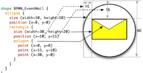
Fig. 4 Shape DSL BPMN EventMail example definition
is therefore developed. A shape number of shape definitions, which represents a pictogram in Graphiti
of primitive forms like ellipse, rectangle and polygon. Furthermore, these basic shapes can public class DmodelCustomOpenModelElementFeature extends
DmodelCustomOpenModelElementFeatureBase { @Inject IURIEditorOpener opener;
public DmodelCustomOpenModelElementFeature(IFeatureProvider fp) { opener = Activator.get(IURIEditorOpener.class);
public boolean canExecute(ICustomContext context) {
return getBusinessObjectForPictogramElement(context.getInnerPictogramElement()) !=
public void execute(ICustomContext context, EObject object) { opener.open(EcoreUtil.getURI(object), true);
Aug 2016
Page 16 container (rectangle), text (text field) and for simple box-and-line editors like class diagrams, but not for more regarding the shapes. The so not intended to describe the appearance of items in detail, but merely the
pictograms.
In order to describe more complex graphical language (file extension
BPMN EventMail example definition
International Journal of Computer Techniques -– Volume 3 Issue 4, July - Aug 2016
ISSN :2394-2231 http://www.ijctjournal.org Page 17 nested in any order and depth. The position of the
nested element(s) is indicated by the position. Figure 4 describes the definition of the Business
Processing and Modelling Notation (BPMN) symbol “Event Mail” in spray shape definition language and the resulting graphical symbol. Each shape is represented by the code generator to a class that implements the interface ISprayShape. Also here the value of the code generation becomes apparent. From the 15 lines of the shape definition (4 lines closing brackets) will be Java code (Graphiti) generated of almost 100 lines. In addition, shape DSL is much more readable and understandable than the Java code.
Anchors are the points at which connections can be attached to a shape. Without further specification, this is the edge of the outermost element (for ellipses there is an enclosing invisible rectangle). With the keyword anchor it’s possible to define anchor points of a shape. The position information of anchors can be either fixed (x / y position definition of a coordinate) or dynamic (xoffset / yoffset percent with respect to the invisible rectangle). Additionally, there are the pre-defined anchor points centre (anchor center) and corners
(anchor corners).
Lis. 7 Anchor example definition
Thus even very complex shapes can be defined. Their appearance can be customized by changing colours, fonts, line thickness and other characteristics. This “Styles” can be described by an additional language, which is comparable in its task to CSS.
C. Definition of Styles
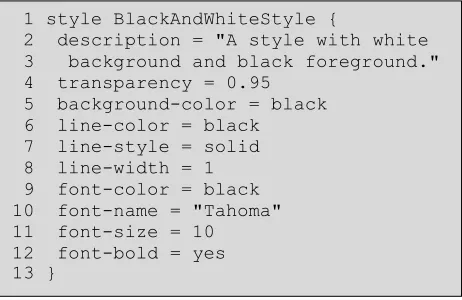
Styles are defined in files with the extension *.style. A style description offers for example the possibility to describe the following features:
• Colours (background and foreground) • Font (name, size, italic, bold)
• Lines (width, style, colour)
Styles can inherit from one another, so that a hierarchical structure of properties can be constructed. For each style definition Spray produces a Java class that implements the interface ISprayStyle. These can then be used in other spray languages or directly in your code. Listing 8 shows an example style definition.
Lis. 8 Style DSL example definition
D. Integration of the languages
The defined shapes in the shape DSL can be referenced in the spray DSL when mapping of elements by specifying the shape keyword (Lis. 9).
Lis. 9 Spray DSL shape reference
The link between the shape and displayed characteristics of the model is established by the definition of parameter values in the shapes and the surrender values in the spray model. Thus the shapes remain independent of the specific metamodel. This allows the creation of Shape libraries which can be used in any Graphiti editor, regardless of spray itself.
The styling of a shape is achieved by referencing an existing style definition (Lis. 10). The children of a composite shape inherit the style information, which can be overridden if necessary.
Lis. 10 Spray DSL style reference
1 anchor corners { 2 position(x=5, y=10) 3 position(x=50, y=100) 4 }
1 style BlackAndWhiteStyle {
2 description = "A style with white 3 background and black foreground." 4 transparency = 0.95
5 background-color = black 6 line-color = black
7 line-style = solid 8 line-width = 1 9 font-color = black 10 font-name = "Tahoma" 11 font-size = 10 12 font-bold = yes 13 }
1 class mail: shape BPMN_EventMail
International Journal of Computer Techniques
ISSN :2394-2231
Individual style properties can be overwritten directly without the need for a style definition.
V.THEGENERATEDEDITOR
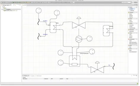
The generated graphical editor is a fully functional set of Eclipse Plugins. The generated graphical editor is divided into four different areas. The area on the left side displays the
explorer. The package explorer includes the different created diagrams and offers the option to create new diagrams. The right side contains the user specific defined elements described with the shape DSL. The lower area is used to view different Properties of the elements according to the specified properties in the main DSL. The area is used to draw the actual specific
which is compliant to the defined Metamodel. Figure 9 shows an example Graphical Editor an example Diagram of a Piping and Instrumentation Diagram.
Fig. 5 The generated Graphical Editor in Eclipse
VI. LIMITATIONS OF THE APPROACH
The described project is by no means finished and still lacks a number of important features before its use could be recommended in the context of mission critical development. Bu
improve over time. Also, it is an open source project and can be extended and improved by anyone in need of extensions to it.
Examples of such features are improved support for text, the inclusion of shadows and gradients, support for context menu and the use of rapid buttons. More important is the question of the limitations of the approach. In terms of the
International Journal of Computer Techniques -– Volume 3 Issue 4, July - Aug 2016
2231 http://www.ijctjournal.org Individual style properties can be overwritten
directly without the need for a style definition.
The generated graphical editor is a fully functional set of Eclipse Plugins. The generated graphical editor is divided into four different areas. The area on the left side displays the package explorer. The package explorer includes the different created diagrams and offers the option to create new diagrams. The right side contains the elements described with the used to view the elements according to the DSL. The centre actual specific diagram to the defined Metamodel. an example Graphical Editor with Piping and
PPROACH
The described project is by no means finished and still lacks a number of important features in the context of mission critical development. But this will Also, it is an open source project and can be extended and improved by Examples of such features are improved support sion of shadows and gradients, support for context menu and the use of rapid buttons. More important is the question of the limitations of the approach. In terms of the
graphical editor itself, the API offered by Graphiti as well as exploiting its capabili
model driven approach, we see no serous constraints. In this regard, Graphiti provided a lot of features we had expected. Nonetheless we
a few limitations while developing the editor. For example, Graphiti currently does not support underlining of text, a feature we would need i.e. for static members in a UML class diagram. Another limitation is the standard zooming function within Graphiti diagrams. The framework zooms by resizing all sizes of the elements, including the border-size. This leads to unproportioned
Zooming currently only works well between 75 and 150%. Finally, the Graphiti API allows a few things that surprisingly have no effect on the diagram. This lead to the workaround that we use an invisible rectangle at the root level of every shape.
The generative approach is somewhat limited to cases that are needed often enough to justify the development of a generator and the according input models. Corner cases could be covered with additional parameters in the input to the generator, however, the generated code is well prepared for manual extensions, so that this could turn out simpler. The DSLs presented by us are targeted towards graphical languages based on the notion of nodes and edges. In UML most diagram ty into that category, however it includes a few exceptions. The sequence and the timing diagram show time as one dimension and differ in that sense. They cannot be described with the presented DSLs without considerable extensions.
We see more limitations in the platform of Eclipse itself. Eclipse was developed as a text centric software development tool, and this heritage remains visible to the day. An example for this is that Eclipse ends a transaction of a file change upon saving this file. However, models on a scale larger than just one diagram need a different semantic for changes. Model elements can be represented in several diagram views. Modelling
to expect a change in one such representation to be reflected in the others immedia
case in repository based modelling this is hard to achieve in Eclipse.
Other topics, like multi
collaborative modelling environments, evolution of Aug 2016
Page 18 graphical editor itself, the API offered by Graphiti as well as exploiting its capabilities through a model driven approach, we see no serous constraints. In this regard, Graphiti provided a lot of features we had expected. Nonetheless we analysed a few limitations while developing the editor. For example, Graphiti currently does not support the underlining of text, a feature we would need i.e. for static members in a UML class diagram. Another limitation is the standard zooming function within Graphiti diagrams. The framework zooms by resizing all sizes of the elements, including the unproportioned borders. works well between 75 and the Graphiti API allows a few things that surprisingly have no effect on the diagram. This lead to the workaround that we use an invisible
at the root level of every shape.
The generative approach is somewhat limited to cases that are needed often enough to justify the development of a generator and the according input models. Corner cases could be covered with nput to the generator, however, the generated code is well prepared for manual extensions, so that this could turn out simpler. The DSLs presented by us are targeted towards graphical languages based on the notion of nodes and edges. In UML most diagram types fit into that category, however it includes a few exceptions. The sequence and the timing diagram show time as one dimension and differ in that sense. They cannot be described with the presented DSLs
ithout considerable extensions.
ions in the platform of Eclipse itself. Eclipse was developed as a text-centric software development tool, and this heritage remains visible to the day. An example for this is that Eclipse ends a transaction of a file change upon models on a scale larger than just one diagram need a different semantic for changes. Model elements can be represented in Modelling users have come to expect a change in one such representation to be reflected in the others immediately, as this is the modelling tools. However, this is hard to achieve in Eclipse.
International Journal of Computer Techniques -– Volume 3 Issue 4, July - Aug 2016
ISSN :2394-2231 http://www.ijctjournal.org Page 19 metamodels, or diffing and merging changes in
versions of graphical models remain topics of research and are independent of Eclipse or a model driven approach.
VII. EVALUATION
The presented generative approach reduces the effort of the development of a graphical editor for Eclipse considerably compared to the manual coding against the Graphiti API. The Graphiti framework needs for every domain object a set of so called features descriptions. The generator creates for each domain object the needed feature skeletons / implementations (Add-, a Create-, a Layout- and an UpdateFeature), which altogether consist of at least 400 lines of code per domain object. These can be generated by Spray from about 10 lines of code. This allows to focus the development on the actual important logic and is not slowed down by the needed overhead of the Graphiti framework.
VIII. CONCLUSIONS
In this paper we have shown that developing graphical DSLs with the usage of the open source framework Spray can be very efficient. We presented concepts for the model driven development of graphical modelling tools in the context of Eclipse. The modelling tools can be configured to the needs of a specific domain, resulting in an Eclipse plugin that supports a graphical domain specific language. It is not necessary to be an IT expert to develop such modelling tools, because the DSLs are quite easy to learn, read and write. The meta model and the DSLs can be tailored to the specific needs, thus the models can be very concise. In this paper we showed some elements of the BPMN, but the same approach could be used for various domain specific modelling languages.
The generative approach reduces the needed effort to develop a graphical modelling tool for Eclipse considerably compared to coding it manually in Java against the Graphiti API. For the underlying Graphiti framework, every domain object needs to be described by a set of so called features. For each domain object the generator creates an Add-, a Create-, a Layout- and an
UpdateFeature (a lot more planned), which altogether consist of about 400 lines of code per domain object. These can be generated from Spray from about 20 lines of code. The factor in terms of code between the Spray DSLs (20 lines) and the generated Graphiti Code (400 lines) is approximately 20. For several implemented examples we consistently observe this factor. A small DSL developed in Spray with 20 domain objects was described in about 400 lines of code. This generates about 80 Java Classes with altogether 8000 lines of code. Thus we argue that our approach reduces the project cost for developing a graphical DSL in Eclipse from weeks and months (manually written) to hours and days (generative approach). This should make the development of graphical modelling tools in Eclipse much more attractive than in the past.
REFERENCES
[1] Boger, M., Thoms, K., Warmer, J.: Spray - A quick way of creating Graphiti, http://code.google.com/a/eclipselabs.org/p/spray
[2] itemis AG: Xtext 2.0, http://www.eclipse.org/Xtext
[3] The Eclipse Foundation: CDO Model Repository,
http://www.eclipse.org/cdo/
[4] The Eclipse Foundation: Draw2d. http://www.eclipse.org/gef/draw2d/
[5] The Eclipse Foundation: Eclipse Modeling Framework Project (EMF), http://www.eclipse.org/modeling/emf/
[6] The Eclipse Foundation: GEF (Graphical Editing Framework),
http://www.eclipse.org/gef/
[7] The Eclipse Foundation: Graphical Modeling Project (GMP),
http://www.eclipse.org/modeling/gmp/
[8] The Eclipse Foundation: Graphiti: A Graphical Tooling Infrastructure. http://www.eclipse.org/graphiti/
[9] Trompeter, J., Beltran, J.C.F.: Modellgetriebene Softwareentwicklung: MDA und MDSD in der Praxis. Entwickler.Press (2007).
https://books.google.de/books?id=iobrPQAACAAJ
[10] Object Management Group. http://www.omg.org/
[11] MetaCase: MetaEdit+, http://www.metacase.com/mep/
[12] Gentleware AG, Poseidon for DSLs,
http://www.gentleware.com/fileadmin/media/pdfs/tutorials/Poseidon_f or_DSLs_Documentation.pdf
[13] Sparx Systems: Enterprise Architect, http://www.sparxsystems.com/ Addison-Wesley Professional (2011)
[14] No Magic Inc.: MagicDraw, https://www.magicdraw.com/
[15] itemis AG: Xtext 2.0, http://www.eclipse.org/Xtext
[16] Kalleberg, K. T., Visser, E.: Spoofax - An Interactive Development Environment for Program Transformation with Stratego/XT. In T. Sloane and A. Johnstone, editors, Seventh Workshop on Language Descriptions, Tools, and Applications (LDTA 2007), ENTCS, pages 47{50, Braga, Portugal, March 2007. Elsevier.
[17] Graf, A.: A DSL for Graphiti Editors (IMES), Research Project,
http://5ise.quanxinquanyi.de/2011/08/18/a-dsl-for-graphiti-editors/
[18] Markus Gerhart, Marko Boger." Zeta - A Set of Textual DSLs to Define Graphical DSLs ".International Journalof Computer Techniques (IJCT) V3(3): Page(29-43) May - June 2016. ISSN: 2394-2231. www.ijctjournal.org.Published by International Research Group- IRG. [19] Efftinge, S., Eysholdt, M., Köhnlein, J., Zarnekow, S., von Massow, R.,
International Journal of Computer Techniques -– Volume 3 Issue 4, July - Aug 2016
ISSN :2394-2231 http://www.ijctjournal.org Page 20