R E S E A R C H
Open Access
An improved method for color image editing
Bekir Dizdaro
ğ
lu
*and Cevat
İ
kiba
ş
Abstract
In this article, an improved approach for editing color images has been presented. In this approach, using the Poisson equation, a guided vector field is created by employing source and target images within a selected region at the first step. Next, the guided vector is used in generating the result image. Most of the existing techniques in the literature perform image editing without taking color information into account. However, without utilizing color information, image geometry cannot be created properly in some cases which may result in unsatisfactory results. Unlike the existing methods, the proposed study utilizes all the information contained in each of the color channels in computing gradient norm and performing inpainting process. The test results show that the suggested technique generates satisfactory results in editing color images.
Keywords:Poisson equation, guided interpolation, editing color images, inpainting color images, calculation of gradient of color images, seamless and mixed seamless image cloning, arranging local illumination changes, tex-ture flattening, covariant inpainting
1. Introduction
Digital image processing operations are related with glo-bal changes including image correction, filtering, colori-zation, or local changes in a selected region where altering processes take place. Commercial or artistic photomontages take the local changes in images into account. Along with the technologic improvement, some softwares, such as Adobe©
Photoshop©, have been released for image editing. However, professional experi-ence is required to be able to use those kinds of soft-wares efficiently, and editing photos by the indicated software is tiresome. In addition, the regions altered using those tools may include some visible artifacts.
Digital image editing methods based on the Poisson equation have frequently been used in recent researches [1-12]. Perez et al. [1] presented an image editing approach based on the Poisson equation with Dirichlet boundary conditions. However, using this method, color inconsistency may occur in edited regions of images. Sun et al. [2] proposed an image matting algorithm with the Poisson equation. However, because of a long pro-cessing time, the method is not practically usable. Chuan et al. [3] improved the method that was sug-gested by Perez et al. to overcome the color
inconsistency problem. But, the experiments show that the improved method is still too complex. Leventhal and Sibley [4] suggested an alpha interpolation techni-que to remove brightly colored artifacts caused by mixed seamless image cloning in edited images. Jia et al. [5] presented a method, called drag-and-drop pasting, which computes an optimized boundary condition auto-matically by employing a new objective function. How-ever, the method is compared not with mixed seamless image cloning but with only seamless image cloning approach proposed in [1]. Georgiev [6-8] developed a new method that is invariant to relighting and handles seamlessly illumination change including adaptation and perceptual correctness of results. The method processes the image by considering its surrounding texture con-trast as well. Fattal et al. [9] presented a method to ren-der high dynamic range images on a monitor using a Poisson equation. Shen et al. [10] suggested a method whose outputs are generated from the gradient maps by employing a Poisson equation. Dizdaroğlu and İkibaş [11] introduced a color image editing method with the Poisson equation, on which this study was built. Yang et al. [12] proposed a variational model, a distance-enhanced random walks algorithm and a multi-resolu-tion framework based on the Poisson image editing method. Although many methods were summarized related with the research area, most of those methods are complex or may cause artifacts because of
* Correspondence: [email protected]
Computer Engineering Department, Karadeniz Technical University, 61080 Trabzon, Turkey
independent implementation of each color channel, or using only the lightness channel.
In this article, we present a digital image editing method that utilizes all the information contained in each of the color channels based on the Poisson equa-tion. The test results show that the proposed method generates output images in a seamless manner with no blurring artifacts.
2. Image editing
Let f: Ω®Rnandf:Ω®Rbe color (n= 3) and grayscale images, respectively, and they are defined on domain of
Ω®R2
.fi:Ω®Rstands for the image channel ioff(1 ≤
i ≤ n): ∀p = (x, y)ÎΩ. The proposed method will be explained in detail in the following sections.
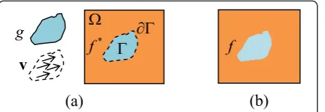
The Poisson image editing is basically a process of obtaining a new result imagefusing the source imageg and target imagef*. In this method, the guided vector field v is first created using both the imagesgandf*. After that, the method reconstructs the imagefwith Dirichlet bound-ary conditions so that the gradient offis closest in theL2
-norm to v over the regionΓ, while satisfyingf=f* over
∂Γ[1,4]. Therefore, the edited image region includes the features of both imagesgandf*, and matches the rest of the image in a seamless manner (see Figure 1).
A basic approach for editing process is to minimize the variation of the image fover the region Γ by esti-mating the gradient norm ||∇f||, which is also known as Tihkonov regularization [13]:
min
f:→RE
f=
∇f2 f∂= f∗∂ (1)
In Equation 2, theimage gradientdenoted by∇fis the first-order derivative of the grayscale image f with respect to its spatial coordinatesp= (x,y):
∇f =fx,fy
T
=
∂f ∂x,
∂f ∂y
T
(2)
In order to represent magnitudes of the grayscale imagef and its maximum variation directions, a vector
∇f: Γ®R2 is created. Scalar and point-wise measure-ment of the image variations are given by the gradient norm ||∇f||, which is used in image analysis in many cases:
∇f= f2
x +fy2 (3)
Here, fx and fy are the first-order derivatives of the
image finxandy directions, respectively. These can be calculated using Taylor’s formula. Figuring out the func-tionf minimizing the functionalE(f), requires complex processing operations. A necessary condition is given by the Euler-Lagrange equations, which must be confirmed byfto reach a minimum ofE(f):
∂E ∂f =
∂F ∂f −
d dx
∂F ∂fx−
d dy
∂F ∂fy
= 0, f∂= f∗∂ (4)
whereF=∇f2= f2
x +fy2
2
.
The calculation of d
dx ∂F ∂fx
and d
dy ∂F
∂fy according to the
standard differentiation rules is as follows:
∂F ∂fx
= ∂ ∂fx
f2
x +fy2
2 = 2fx
d dx
∂F ∂fx
= d
dx
2fx
= 2fxx
and
d dy
∂F ∂fy
= d
dy
2fy
= 2fyy
(5)
Accordingly, −2fxx+fyy
= 0 is found as a solution to Equation 5. Constant 2 may be removed from the equation for simplicity.
A classic iterative method called gradient descent is used for solving the partial differential equation (PDE) in Equation 1. As a matter of fact, Equation 1 can be seen as the gradient of the functional E(f). A local minimizer fmin of E(f) can be found by starting from finitial and then following the opposite direction of the
gradient: ⎧ ⎪ ⎨ ⎪ ⎩
f(t=0)=finitial ∂f
∂t =− ∂
F ∂f −
d dx
∂F ∂fx −
d dy
∂F ∂fy
(6)
Solving the equation:
∂f
∂t =fxx+fyy=f, f∂= f
∗
∂ (7)
is found. Here, Δ is the Laplace operator, and also Taylor’s formula is used in finding second-order
g
*
*f
f
*
w
v
:
(a)
(b)
derivatives offxxandfyy. Equation 7 is called asdiffusion
orheat equation.
Basically, Equation 7, at a particular timet, gives the convolution of finitialwith a normalized 2-Dimensional Gaussian kernel Gs of variance σ =√2t:finitial∗Gσ
which means the linear smoothing, where
Gσ= 1 2πσ2exp
−x2+y2 2σ2
[14-16].
The regularization PDE shown in Equation 8 is com-patible with the approach expressed above:
⎧ ⎨ ⎩
f(t=0)=finitial
f(t+1)=f(t)+dt∂
f(t) ∂t
(8)
wheredtrepresents adapting time step.
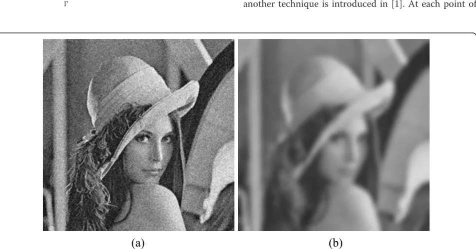
As clearly followed above, the image is gradually blurred in anisotropicway during the PDE evolution. Here, isotro-pic smoothing acts as alow-pass filtersuppressing high frequencies in image off. Unfortunately, since image edges and noise are both high frequency signals, the edges are quickly blurred as seen in Figures 2 and 3c. Therefore, the interpolation operation based on a guided vector field could generate a better result [1].
A function, minimizing the difference between the gradient∇fof imagefand guided vector fieldvover the region Γ, should be found. The equation given below can be used for this operation:
min
f:→RE
f=
∇f−v2, f∂ = f∗∂ (9)
The result is found when the above equation is solved by the Poisson equation with Dirichlet boundary condi-tions as follows:
f = divv, f∂ = f∗∂ (10)
Here, divv= ∂u ∂x +
∂v
∂y is the divergence of v = (u,v).
This is a fundamental equation used in digital image editing.
The guided vector field v can directly be obtained from the source image g. In this case, the interpolation operation is conducted considering the equation as fol-lows:
v=∇g (11)
Equation 12 is obtained for seamless image cloning, if Equation 10 is reorganized accordingly:
f =g, f∂ = f∗∂ (12)
Therefore, the source image is seamlessly cloned to the target image without blurring artifacts within the user-selected region as seen in Figure 3d. If the source image is directly copied to the destination image, some visual annoying effects may reveal in the result image as shown in Figure 3b.
Seamless image cloning method may result in blurring artifacts in the image editing region if the user-selected boundary intersects with prominent structures in the target image as seen in Figure 4c. To solve this problem, another technique is introduced in [1]. At each point of
(a)
(b)
the regionΓ, if stronger variations on any of the source imagegor the target imagef* is to remain the same, the following vector field can be used for mixed seamless image cloning as seen in Figure 4e.
∀p∈, v(p)=
∇f∗(p)if∇f∗(p)>∇g(p),
∇g(p) otherwise. (13)
Another approach for image editing is arranging local illumination changes [1]. In this method, the guided vector field can be defined as follows to arrange the illu-mination changes in any region of the image as shown in Figure 5a,b.
v(p)=αβ∇f∗(p)−β∇f∗(p) (14)
with a = 0.2 times the average gradient norm of f* overΓ and,b= 0.2.
Also, the gradient ∇f* of the target image can be passed through a sparse sieve [1]. Therefore, it is retained only the most prominent features on the image, which is called texture flattening. This is performed by applying on Equation 15:
∀p∈, v(p)=M(p)∇f∗(p) (15)
where M is a binary mask obtained using an edge detection approach as depicted in Figure 6a,d.
An efficient method presented in [6-8] utilizes not only pixels values but also texture contrasts while editing the selected region seamlessly as illustrated in
(a)
(b)
(c)
(d)
g
*
f
f
f
f
Figure 7. In this figure, we cannot perceive pixel values precisely because of the fact that a variable background encloses a rectangle which is a constant color. Here, whereas pixel gradient is zero, perceived, or covariant gradient is not zero. Consequently, the following equa-tion is invariant relighting and considers illuminaequa-tion changes [6-8] as seen in Figure 8a,g.
f f −2
∇f f ·
∇g g −
g g + 2
∇g· ∇g
g2 = 0 (16)
This approach, covariant Laplace equation, can be considered as a Poisson equation with a modifiedΔg term. Actually, the above equation can be seen as equal
to f
g = 0 by calculating simple differentiation. The
equation is solved in three main steps for covariant inpainting which fills the image holes by propagating
linear structures of the source region into the target region by means of diffusion process utilizing the Pois-son equation approach [6,8].
These steps are
(a) Dividing the result imagefby the source imageg. (b) Solving the PDE in the user-selected region. (c) Multiplying the result by the source imageg.
3. The proposed method
The method studied in [1] utilizes each color channel of the image in the Poisson equation independently. In other words, classical scalar diffusion PDEs on each channelfiof the initial image finitialis used while
proces-sing color images in many applications. However, since each image channel fi evolves independently with
differ-ent smoothing geometries, this approach is useless because of linear structures of the image that have dif-ferent directions for each vector componentsfi. Even if
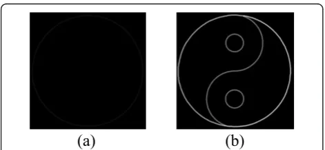
these directions are relatively close to each others, the diffusion process will not behave in a coherent way and a high risk of vector components blending (that will blur the edges) may occur [17]. In addition to this, the exact geometric structure of the image may not be obtained if all the information contained in each of the color channels is considered. Consequently, the image structure may inaccurately diffuse to the target region. Figure 9 shows the lightness channel component of the test image in CIE-Lab color space. Examining the image carefully, it is seen that the lightness channel of the image was not able to be obtained properly. In this case, as can clearly be seen in Figure 9b, insufficient results may be obtained when the image is edited based on gra-dient norm of the lightness channel. Therefore, image editing should be done by considering the effects of color channels on each other.
Before explaining the proposed color image editing in details, it is worth to mention the essentials of
(a) (b)
(f) (e)
(d) (c)
Figure 4Test images used in seamless and mixed seamless image cloning methods: source image and selected region on it (a), target image(b), result images produced using seamless and mixed seamless image cloning methods proposed in [1](c,e), and in this study(d,f), respectively.
(a)
(b)
(c)
inpainting color images. In recent years, many notable approaches have been developed for image inpainting, or completion [14,15,17-22]. Our proposed method employs trace-based PDE method in which the local geometry of the color image can be calculated based on all the information contained in each of the color chan-nels as follows:
∀p∈, J(p)=
n
i=1
∇fi∇fiT
where∇fi=
⎛ ⎜ ⎝
∂fi ∂x ∂fi ∂y
⎞ ⎟
⎠ (17)
Jis defined as follows for a color imagef= (R,G,B):
J=
j11j12
j21j22
=
R2
x+G2x+B2x RxRy+GxGy+BxBy RyRx+GyGx+ByBx R2y +G2y +B2y
(18)
The positive eigenvalues l+/- and the orthogonal eigenvectorsθ+/-ofJare formulized as follows:
λ+/−= j11+j22± j11−j22
2 + 4j122 2
(19)
and
θ+/−=
2j12
j22−j11± j11−j22 2
+ 4j122
(20)
More consistent geometry is obtained, provided that
Js=J*Gsis smoothed by a Gaussian filter. Here, Jsis a
good estimator of the local geometry offat point p. Its spectral elements give the vector-valued variations (by
(b)
(c)
(d)
(e)
(a)
Figure 6Test image used in texture flattening approaches: input image(a), results of texture flattening approaches: gradient norm of the image calculated by proposed method(b), binary mask calculated from the gradient norm(c), the result produced by [1](d), and the result produced by our method(e).
the eigenvaluesl+, l-, ofJs) at the same time and the orientations (edges) of the local image structures (by the eigenvectorsθ+⊥θ-ofJs).
Thegradient norm ||∇f|| of the color imagef is easy to compute as follows since it perceives image structures successfully [14,15] (see Figure 10):
∇f=√λ++λ−=
n
i=1
∇fi2 (21)
Tschumperlé and Deriche [14] suggested designing a particular field T: Γ®P(2) of diffusion tensors to
(a)
(b)
(e)
(f)
(c)
(d)
(g)
(h)
define the specification of the local smoothing method for the regularization process. Apparently, it should be noticed thatT, depending on the local geometryJsoff, is thus defined from the spectral elementsl+,l-, andθ+,
θ
-ofJs:
∀p∈, T(p)=s−λ+,λ−θ−θ−T+s+λ+,λ−θ+θ+T (22)
The strengths of smoothing alongθ+andθ-are set by two functions denoted bys-/+: R2®R, where the types of applications determines-and s+. Sample functions for image denoising are proposed in [14]:
s−λ+,λ−= 1
(1 +λ++λ−)a1ands
+λ+,λ−= 1
(1 +λ++λ−)a2whilea1<a2 (23)
Here, the goal of smoothing operation can be listed as follows:
• The pixels on image edges are smoothed alongθ -with a strength inversely relative to the vector edge strength (anisotropic smoothing).
•The pixels on homogeneous regions are smoothed along all possible directions (isotropic smoothing).
Tschumperlé and Deriche [14] present a regularization-PDE-based approach to agree with the local smoothing geometryTbased on atraceoperator:
∂f ∂t =
∂fi
∂t = trace(THi) (24)
whereHiis the Hessian matrix offi:
Hi=
∂2f i
∂x2 ∂ 2f
i
∂x∂y
∂2f i
∂y∂x
∂2f i
∂y2
(25)
In this study, Hi is a symmetric matrix since the
images are regular ones and ∂2fi
∂x∂y =
∂2f i
∂y∂x.
As Tschumperlé and Deriche [14] have shown, Equation 24 can be viewed as a local filtering approach with oriented and normalized Gaussian kernels. Here, a small convolution is locally applied around each pointp with a 2D Gaussian mask GTtorientedby the tensorT(p):
GTt (p)= 1 4πtexp
−pTT−1p 4t
(26)
As a matter of fact, a link exists between anisotropic diffusion PDE and classical filtering techniques:
∂fi
∂t =trace(THi)⇔fi(t)=fi(t=0)∗G
T
t (27)
The regularization PDE shown in Equation 27 is compa-tible with all local geometric properties expressed above:
⎧ ⎨ ⎩
f(t=0)=finitial
f(t+1)=f(t)+dt∂ f(t) ∂t
(28)
with the diffusion tensor T=s−λ+,λ−θ−θ−T. The approach in [1] is implemented by our method to seamlessly clone the source image to target image, which is shown in Equation 29.
fi=gi, fi∂ = fi∗∂ (29)
Here, in our seamless image cloning method, each image channel fi evolves independently with different
smoothing structures as depicted in Figure 11. However, unlike the method proposed in [1], we apply a cutting approach on pixel values in the processed image and a linear normalization method on the result image to obtain a better visual result as seen in Figure 12e.
Equation 13 employed in mixed seamless cloning method can be rewritten as below by considering all the information contained in each of the color channels:
∀p∈, vi(p)=
∇fi∗(p) if ∇f∗(p)>∇g(p),
∇gi(p) otherwise. (30)
(a)
(b)
Figure 9Color image representation: image in RGB color space (a)and the lightness channelLof the image in CIE-Lab color space(b).
(a)
(b)
i
g
*
i
f
i
f
i
v
i i
g
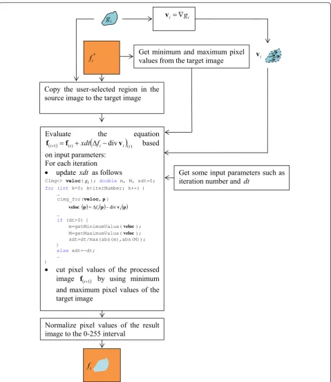
v
Get minimum and maximum pixel
values from the target image
Evaluate the equation
() )(
1 t i
div
i tt
f
xdt
f
v
f
'
based
on input parameters:
For each iteration
x
update
xdt
as follows
CImg<> veloc(gi); double m, M, xdt=0;
for (int k=0; k<iterNumber; k++) { …
cimg_for(veloc,p) p v p p
veloc 'fi div i
…
if (dt>0) {
m=getMinimumValue(veloc); M=getMaximumValue(veloc); xdt=dt/max(abs(m),abs(M)); }
else xdt=-dt; …
}
x
cut pixel values of the processed
image
f
t1by using minimum
and maximum pixel values of the
target image
Get some input parameters such as
iteration number and
dt
Copy the user-selected region in the
source image to the target image
Normalize pixel values of the result
image to the 0-255 interval
In our method, the color image gradient norm is used to obtain the image structure more accurately as shown in Figure 10b.
The mentioned methods in [6,8,9] were applied only on the lightness channel of the image to arrange local illumination changes and to flatten texture. Therefore, we modify the arrangement of local illumination changes and texture flattening methods as stated in Equations 31 and 32, respectively.
vi(p)=αβ∇f∗(p)−β∇fi∗(p) (31)
∀p∈, vi(p)=M(p)∇fi∗(p) (32)
where Mis the binary image obtained by employing ||∇f*(p)||.
Covariant inpainting method presented in [6,8] com-pletes the user-selected region in a seamless manner, which takes into account both pixel values and texture contrast of the surrounding area of the edited region as seen Figure 8f,g. However, in the method diffusion pro-cess is not coherently employed for all the color image channels fi. Therefore, we extend the method in [6,8]
for color image editing to diffuse the image structure accurately to the target region as depicted in Figures 13f and 14b. Namely, to solve Equation 33 for inpainting step, we use a trace-based method [14], which is explained above.
f
g = 0 (33)
Therefore, we calculate only the gradient norm by tak-ing the interaction among the channels into account in order to edit color images using the proposed methods.
However, diffusion process in these methods, except for our covariant inpainting approach, has been done sepa-rately for each color channel.
4. Experimental results
The proposed method is compared with the previous approaches suggested in [1,5-8,12,15,18-21] by utilizing seamless and mixed seamless image cloning, arrange-ment of local lightness variation, texture flatting, multi-resolution cloning considering the color fidelity, covar-iant inpainting, image completion, curvature-preserving PDE-based inpainting, combined PDE and texture synthesis, and variational inpainting approaches. The methods are tested on color images containing RGB color space and some images in referenced papers were utilized in these performed tests. The proposed editing operation is performed on only the selected region marked by the user.
The test results of mixed seamless image cloning using only the lightness channel and our method are shown in Figure 15. Whereas our method is able to pre-serve the image structures in the result image, the method considering the lightness channel fails to protect image edges because of using only the lightness channel of the images while obtaining image gradient norms, as seen in Figure 15c,d.
The test results of seamless image cloning method suggested in [1] and our seamless image cloning approach are depicted in Figure 12. Both methods give almost the same results. But, the result generated by our method has slightly more vibrant colors.
The test results of seamless and mixed seamless image cloning suggested in [1] and our proposed method are given in Figure 4. Both approaches developed for
(a)
(b)
(c)
(d)
(e)
seamless editing method cause blurring on some parts of the edited region of the target image. However, mixed seamless image cloning method does not cause any blurriness on the result image. As seen in Figure 4f, there is almost no color inconsistency on the result image generated by the proposed method since all the
information contained in each of the color channels is used in editing the image. This situation can be clearly observed on variation of color of fume in the result image.
The test results for seamless image cloning proposed in [5] and mixed seamless image cloning in our study
(c)
(d)
(a)
(b)
(e)
(f)
(a)
(b)
Figure 14Close-ups of test image: defect retouched by the covariant inpainting method in [6,8](a)and by our covariant inpainting approach(b).
(a)
(b)
(c)
(d)
are given in Figure 16. The former method performs complex operations to find an optimized boundary con-dition. The method uses a shortest closed-path algo-rithm which is designed to search for the location of the boundary. Its additional computational complexity isO (MN), whereMandNstand for the number of pixels in the band of the boundary. Also, the method employs a blended guidance field to incorporate the object’s alpha matte to preserve the object’s fractional boundary prop-erly. Unlike that method, our proposed method is sim-ple, and it is as effective as the former one. However, in Figure 16g, sea waves can be realized through the man’s body because of the fact that they have prominent struc-tures against to his body. This problem may be solved using a modified Poisson matting method. The
additional time complexity of our method over the mixed seamless cloning method in [1] to compute the color image gradient norm isO((n- 1)L), wherenis the channel number of color images, andL is the number of pixels in the edited region.
Other test results for image cloning are given in Figure 17. The existing seamless image cloning method may diffuse prominent global coloring of the object toward the background as seen in Figure 17d. The method proposed in [12] takes the color fidelity term into account to avoid the problem observed in Figure 17e. Our seamless and mixed seamless image cloning methods generate acceptable results; however, some artifacts may come into existence in the neighborhood of the user-selected region. Also, dominant structures of
(c)
(d)
(a)
(b)
(e)
(f)
(g)
some grasses can be seen through the squirrel’s body in our mixed seamless image cloning method as shown in Figure 17g.
Another experiment illustrates how to conceal balus-trade. The test results generated by the proposed method are given in Figure 18e,f. Figure 18b-d shows the results of methods proposed in [19,15,18],
respectively. Unlike other methods, our seamless image cloning method and the approach proposed in [18] pro-duces visually plausible results on the brick wall and trees as seen in Figure 18d,e. However, curvature-preser-ving PDE-based method in [15] produces too much blurring effects, as depicted in Figure 18c and our mixed seamless image cloning method fails to remove
(a)
(c)
(d)
(e)
(f)
(g)
(b)
the object from the image, because the gradient of the object is more dominant against the user-selected patch as seen in Figure 18f.
The results obtained by applying local lightness arrangement methods are given in Figures 5 and 19. As observed in Figures 5a-c and Figure 19a-c, the edited region is almost flat and the gradient norms in these regions are low. For this reason, both the methods
suggested in [1] and our proposed approach produce acceptable results in terms of visual quality.
The results of texture flattening methods are given in Figure 6. It is seen that our method properly flattens the selected region on the test image.
The results for removing a scratch from a shadow region are depicted in Figure 8. Both covariant cloning methods in [6-8] and our covariant inpainting approach
(a)
(b)
(e)
(f)
(c)
(d)
not only correct the lighting but also reconstruct texture in a seamless manner as shown in Figure 8g,h. However, constrained PDE-based method in [15] and Poisson cloning approach in [6,8] generate visually annoying effects as seen in Figure 8e,f.
The test results for concealing a blotch on a film frame are given in Figure 20. Our covariant inpainting method generates a visually plausible result while the image completion method in [18] produces some block-ing artifacts on the result image. However, the method in [18] works fully automatically, which is not the case for our covariant inpainting approach. Actually, direct cloning and our seamless image cloning methods give good results for this film frame as well, as seen in Figure 20b,c. However, our mixed seamless image cloning method fails to generate the efficient result because of the dominant structure of the object, which the blotch cannot be concealed as shown in Figure 20d.
The results of other tests on defect removal are shown in Figure 13. Our covariant inpainting method, our seamless image cloning approach, and the image com-pletion method in [20] produce better results compared with other methods as seen in Figure 13c,e,f. However, direct cloning, our mixed seamless image cloning meth-ods give visually annoying effects. We are also able to compare our covariant inpainting method with the method presented in [6,8] since it was applied to a grayscale form of the original image. Compared to the method in [6,8], our covariant inpainting approach gen-erates less blurring artifacts and linear structures of the
given image is propagated better, as shown in Figure 14a,b.
Lastly, another test result is given for object removal. Figure 21 shows the result of constrained PDE-based algorithm in [15], variational inpainting method in [21], and our covariant inpainting approach. Unlike other methods, our method gives a good result; however, two different patches must be selected by the user because of not being able to remove the object from the image efficiently.
The methods were implemented in Microsoft Visual C ++ 2005 by employing CImg Library[23]. The program was run on a PC with Pentium 2.20 GHz processor and 2 GB RAM. The average required time depends typically on selected regions as well as image editing methods. The processing time for our covariant inpainting method shown in Figure 13f is about 5 s for seven iterations.
5. Conclusion
In this article, a method is presented for editing color images by effectively using all the information contained in each of the color channels. In this method, gradient norm and inpainting process are utilized by considering the effects of color channels on each other. This approach minimizes the color inconsistency and thus the selected region in the source image is cloned to the target image seamlessly.
As a future task, automatic region selection using moment invariants may be developed so that the
(a)
(b)
(c)
(a)
(b)
(c)
(d)
(e)
(f)
proposed method is improved to be able to generate a faster output. In addition to this, the method will be extended to remove defects such as blotches from old motion pictures since there are proper patches in neigh-bor frames to retouch the current one [22].
6. Competing interests
The authors declare that they have no competing interests.
Received: 8 March 2011 Accepted: 10 November 2011 Published: 10 November 2011
References
1. P Perez, M Gangnet, A Blake, Poisson image editing. ACM Trans Graph. 22(3), 313–318 (2003). doi:10.1145/882262.882269
2. J Sun, J Jia, CK Tang, HY Shum, Poisson matting. ACM Trans Graph.23(3), 315–321 (2004). doi:10.1145/1015706.1015721
3. Q Chuan, W Shuozhong, Z Xinpeng, Image editing without color inconsistency using modified poisson equation, inInternational Conference on Intelligent Information Hiding and Multimedia Signal Processing(2008) 4. D Leventhal, PG Sibley, Poisson image editing extended, inInternational
Conference on Computer Graphics and Interactive Techniques, ACM SIGGRAPH
(2006)
5. J Jia, J Sun, C Tang, H Shum, Drag-and-drop pasting, inInternational Conference on Computer Graphics and Interactive Techniques, ACM SIGGRAPH
(2006)
6. T Georgiev, Covariant derivatives and vision.ECCV 2006, 9th European Conference on Computer Vision, Graz, Austria (May 7-13 2006) 7. T Georgiev, Photoshop healing brush: a tool for seamless cloning. in
Workshop on Applications of Computer Vision in conjunction with ECCV 2004, Prague, 1–8 (May 2004)
8. T Georgiev, Image reconstruction invariant to relighting, inEUROGRAPHICS
(2005)
9. R Fattal, D Lischinski, M Werman, Gradient domain high dynamic range compression, inProceedings of ACM SIGGRAPH 2002, 249–256 (2002) 10. J Shen, X Jin, C Zhou, CCL Wang, Gradient based image completion by
solving the Poisson equation. Comput Graph.31(1), 119–126 (2007). doi:10.1016/j.cag.2006.10.004
11. B Dizdaroğlu, Cİkibaş, A seamless image editing technique using color information. inIPCV’09: International Conf. on Image Processing, Computer Vision & Pattern Recognition, Las Vegas, USA (July 13-16, 2009)
12. W Yang, J Zheng, J Cai, S Rahardja, CW Chen, Natural and seamless image composition with color control. IEEE Trans Image Process.18(11), 2584–2592 (2009)
13. AN Tikhonov, Regularization of incorrectly posed problems. Soviet Math Dokl.4, 1624–1627 (1963)
14. D Tschumperlé, R Deriche, Vector-valued image regularization with PDE’s: a common framework for different applications. IEEE Trans Pattern Anal Mach Intell.27(4), 506–517 (2005)
15. D Tschumperlé, Fast anisotropic smoothing of multi-valued images using curvature-preserving PDE’s. Int J Comput Vis.68(1), 65–82 (2006). doi:10.1007/s11263-006-5631-z
16. B Dizdaroğlu, Solving heat flow equation for image regularization, inThe 1st International Symposium on Computing in Science & Engineering (ISCSE), Aydin, Turkey, 372–377 (June 3-5, 2010)
(a)
(b)
(c)
(d)
17. D Tschumperlé, PDE’s based regularization of multivalued images and applications, PhD thesis, Université de Nice-Sophia Antipolis (December 2002)
18. B Dizdaroğlu, An image completion method using decomposition. EURASIP J Adv Signal Process (2011). Article ID 831724, 15
19. G Harald, Combined PDE and texture synthesis approach to inpainting. Proc ECCV.2, 214–224 (2004)
20. C Barnes, E Shechtman, A Finkelstein, DB Goldman, PatchMatch: a randomized correspondence algorithm for structural image editing. ACM Trans Graph.28(3), 24:1–24:11 (2009)
21. A Bugeau, M Bertalmío, V Caselles, G Sapiro, A comprehensive framework for image inpainting. IEEE Trans Image Process.19(10), 2634–2645 (2010) 22. B Dizdaroğlu, A Gangal, A spatiotemporal algorithm for detection and
restoration of defects in old color films. Lecturer Notes in Computer Sciences.4678, 509–520 (2007). doi:10.1007/978-3-540-74607-2_46 23. D Tschumperlé, The C++ template image processing library, The CImg
Library. http://cimg.sourceforge.net/
doi:10.1186/1687-6180-2011-98
Cite this article as:Dizdaroğlu andİkibaş:An improved method for color
image editing.EURASIP Journal on Advances in Signal Processing2011
2011:98.
Submit your manuscript to a
journal and benefi t from:
7Convenient online submission
7Rigorous peer review
7Immediate publication on acceptance
7Open access: articles freely available online
7High visibility within the fi eld
7Retaining the copyright to your article

, andin this study (d, f), respectively.](https://thumb-us.123doks.com/thumbv2/123dok_us/1144640.1143617/5.595.56.290.88.253/seamless-seamlessimage-selected-seamless-andmixed-seamless-proposed-respectively.webp)
, by Poisson cloning approach in [6,8](f), by covariant cloning method in [6,8](g), and by our covariant inpainting method (h).](https://thumb-us.123doks.com/thumbv2/123dok_us/1144640.1143617/7.595.57.539.87.588/artificially-illuminated-inpainting-constrained-basedmethod-covariant-covariant-inpainting.webp)
, and our seamless image cloning method (e).](https://thumb-us.123doks.com/thumbv2/123dok_us/1144640.1143617/10.595.61.540.88.267/seamless-selected-resultimages-produced-approach-proposed-seamless-cloning.webp)
![Figure 13 Test image used in removing a defect(e)retouched by our seamless image cloning method: input image (a), results of direct cloning from the other area of the image (b), defect (c), by our mixed seamless image cloning method (d), by image completion method in [20], and by our covariant inpainting approach (f).](https://thumb-us.123doks.com/thumbv2/123dok_us/1144640.1143617/11.595.59.539.87.605/removing-retouched-seamless-seamless-completion-covariant-inpainting-approach.webp)
