QnQLYflf
Q l:Jb.QQC
U
Db.Vb.
OD
bn
n
G
J
n
nG
T. PAUL,
I NNESOTA
.
CD o
o
eft
N
)(
•
SUMMARY ~ CHARACTERISTICS
MAGNETIC DRUM BINARY COMPUTER
proposed for Mational Bureau of standards
u.s.
Department of CommerceContract CST-lOl"
Pub. Moo 2,
•
~
t·
, ~
,
ENG I NEE R I N G RES EAR C H ASS 0 C I, ATE S •
1902 west Minnehaha Avenue, sto Paul -, Minnesota
e·
•
NBS COMPUTER CHARACTERISTICS 1
PREFACE
This report has been prepared tor the lational Bureau of Standards, U.S.
08-partment of Commeroe, as one phase of the work performed under Contraot CS'f-10133.
Ita purpose is to summarize the characteristios ot a digital oomputer employing
magnetic drum data storage. This somewhat oondensed 8ummary ia intended to serTe
aa the engineering basis for negotiations leading to a possible oontract tor the
oonstruotion of a computing machine, in acoordanoe with agreements reaohed at a
oonferenoe in St. Paul on
5
NOTember1948.
The properties ot the machine are de·fined in sutfioient detail to be useful to aqyone wishing to program8ample
prob-lema tor the purpose of evaluating the speed and general utility of the maohine.
In complianoe with the terms ot the oontract, the described oharacteristics
are baaed on teohniques which are either in active development or have been
sub-jected to detailed critioal analysis.
Preliminary reports outlining three variations on the design of a magnetio
drum oomputer were submitted on 13 August, 30 September, and
19
October1948.
These are listed as Referenoes (a), (b), and (c) in Appendix A. The present
ma-ohine is different from those previously described.
e·
e
•
NBS CO~ER CHARACTERISTICS
TABLE OF CONTENTS
CHAPTER 1 - FUNCTIONAL DESCRIPTIOI
or
COMPUTERSection
1.1 Introduotion
The Computer • • • • • • • • • • • • • • • • • • • • • Parallel transmission and statio retention
ot
data •• Fi?e aections of the computer. • • • • • • • • • • • •1.2
Storage Seotion•
• • • ••
• • • •
•
•
•
• • • •
•Organization ot the drum • • • • • • • • • • • • • • • • • • • • •
Physioa1 charaoteristic' • • • • • • • • • • • • • • • • • • • • • Funotional desoription • • • • • • • • • • • • • • • • • • • • • •
1.3
Arithmetic Section1.,.1
Components • • • • • ••
• ••
• ••
•
••
• • ••
• • • ••
• • •1.,.2
lumber representation.•
• • • ••
••
• • ••
• • • ••
• • • • •1·'·3
AooUllll1ator. • ••
••
• ••
• • • ••
••
• • • • • • • • • • • •1.,.4
Q-Register• •
• • • • ••
• • • • ••
• •• •
• ••
• ••
••
• •1.'.5
X-Register • • • • • • • • • • • • • • • •• •
• ••
• • • • • • •1.,.6
Shift Counter. ••
•• • •
• • • • ••
• ••
• • • • • • • • • • •1.4
Program Control SeotionComputer instruotions. • • • • • • • • • • • • • • • • • • • • • • Component. • • • • • • • • • • • • • • • • • • • • • • • • • • • • End Point Counter. • • • • • • • • • • • • • • • • • • • • • • • •
1.5
Input Seotion1.5·1
Input medium ••
•
• • • • • ••
• ••
•• •
••
• • ••
• • • ••
1.5.2
Tape reader. ••
• • • ••
••
• ••
•
•
•• • • •
• • • • • • ••
1.5·3
Input control. oharaoteristiosot.
• •
••
• • • • ••
• • • •• •
1.5.4
Input oontrol, meohanismot.
• •
••
•
• • • •
• • • • ••
• • ••
1.5·5
Tape preparation unit. ••
•
• ••
•
• •
• • • ••
•• •
• • • • •1.6
Output Seotion • • • • • • • • • • • • • • • • • • • • • • • • • • • •CHAPTER 2 - COMPUTING CHARACTERI3TICS
Introduotion • • • • • • • • • • • •
•
••
••
•
• • •
••
••
•• • •
EMSIHEER 1MB RESEARCH ASSOC I A T E S INC •
•
~
•
•
NBS COMPUTER CHARACTERISTICS
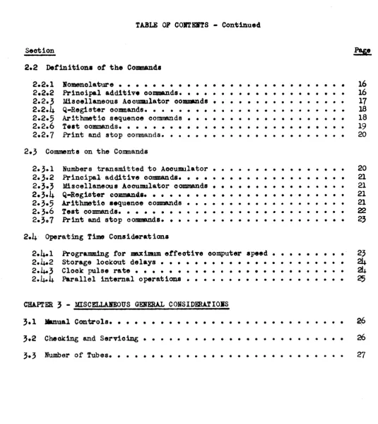
TABLE OF COITErlS - Continued
Section
2.2 Definition. of the Coanandl
2.2.1 Bomenolature • • • •
•
• ••
• • • ••
• • • • • • • • • • • • ••
2.2.2 Prinoipal additive commands. • • • • • • • •• •
• • • • • ••
• •2.2·3
Miscellaneous AooUDlllator oo~d8•
• • • • ••
• • • • • • • • •2.2.4 Q-Register oomnands. • • • • • • • • •
·
• • • • • • •·
• •·
• •2.2·5
Arithmetio sequence oommands•
• • • • • • • • •·
• •·
• •·
• •2.2.6
Teat oommands. • • • • • ••
• • • • • • • • ••
·
• • • • • • • •2.2.7
Print and stop oommands. •·
• • • •·
• • • • • • • • • •·
• • •2.3
Comments on the Comnands2·3·1
2·3·2
2.3·3
2.3.4
2·3·5
2.3.6
2·307
Numbers transmitted to Aocumulator • • Principal additive commands. • • • • • • Misoellaneous Aocumulator commands • • •
• • • • •
• •
••
• • • • • • • • • • • • • • • • •• •
• • • • • • • • • • Q-Register COJDIDaDg.8. • • • • • • • • • • • • • • • • • • • • • • •Arithmetic .equence commands • • • • • • • • • • • • • • • • • • • Test cOJl11ll8nds. • • • • • • • • • • • • • • • • • • • • • • • • • • Print and stop oommands. • • • • • • • • • • • • • • • • • • • • •
2.4
Operating Time Considerationa2.4.1
Programming tor maximwm effeotive computer apeed • ••
••
• •
• •2.4.2
Storage lookout delays • ••
• •• • • •
• • • • • • • • • • • • •2.4.3
Clock pulse rate •• •
• ••
• • • • • •• •
•
• • ••
• • • •·
•2.4-4
Parallel internal o per at ions • • • • • • • • • • • • • • • • • • • CHAPl'ER3 -
mscELLAl'Eous
GERERAL COISIDERA.TIOJlSManual Controls. • • • •
•
• • • ••
• • • • • • • •• ••
• • • • ••
111
16
16
17
18 1819
20 20 21 21 21 21 2223
23
24
24-25
3.2
Checking and Servicing • • • • • • • • • • • • • • • • • • • • • • ••26
Number of Tubes. • • • •
•
•
• • • • ••
••
• • • • • • • • • • • • •27
e-e
e
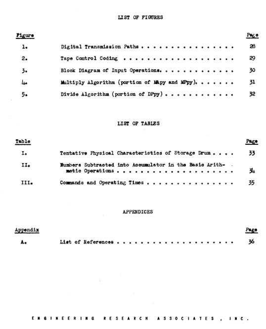
Figure
1.
2.
Table
I.
II.
III.
Appendix
IBS COJlPM'ER CBAR.A.CTERISTICS
LIST OF FIGURES
Digital Transmdssion Paths • • • • • • • • • • • • • • • •
Tape Control Coding • • • -. • • • • • • • • • • • • • • •
Block Diagram
or
Input Operations • • • • • • • • -•• ••
•
Il1ltip1y Algorithm (portionot
1&py and MPpy). •Divide Algorithm (portion
ot
DPpy) • • • • • •• •
•
•
•
• •
•
• ••
LIS'!' OF TABLES
Tentative Physical Characteristics
ot
Storage ~. • • •lumbers Subtracted into Accumulator in the Basio Arith-aetic Operations • • • • • • • •
•
•
•• •
• • ••
• • •Coumands and Operating Times • • • • • • • • • • • • • • •
APPENDICES
List of References • • • • • • • • • • • • • • • • • • • •
1T
29
30
31
32
!!2
33
~
35
BSS COMPUTER CHARACTERISTICS 1
e·
CHAPTER 1
FUNCTIONAL DESCRIPTION OF THE COMPUTER
1.1 Introduotion.
1.1.1
The oomputer. The device whose properties are the subjeot ot thisre-port is a general purpose electronio binary oomputer with magnetio drum internal data storage. It is a selective sequence machine which employs a "two-address"
system of logic tor tollowing a program of instructions.
1.1.2 Parallel transmission and static retention of data. Figure 1 is a
block diagram showing the paths over whioh digital data are transmitted between
the principal units ot the oomputer. (This is not a oomplete blook diagram ot the
e
computer.) In the transmissionot
digital signals, the presenoe of a pula. in a ohannel represents a 1 and the absence ot a pulse ao.
The digits of a multidigite
number are transmitted simultaneously over a multichannel bus. All digital
infor-_tion "in prooess" within the oomputer (excluding that whioh is in magnetio
.torage) i8 held on registers made up of toggle-cirouits, or statio flip-flops.
A toggle-oirouit is a vacuum tube cirouit whioh has two &table atatea. It is
therefore capable of retaining, or remembering, a single b mary digit. In Figure
1, eaoh toggle-oirouit register is indioated lohematioally aa a reotangle with two
tnput terminals, labelled 0 and 1, and two output terminals, similarly labell.d.
The symbol whioh repreaents a 30-digit register may be thought ot aa a composite
ot 30 individual toggle-oirouits, eaoh one ot whioh may be represented by a II im1lar
kind of symbol. It the 0 input terminal
or
a to~gle is pulsed. the 0 output t ..-min&! beoomes positive. It the 1 input terminal is pulsed, the 1 output terminal
beoomes positive.
.'
•
IBS COMPUTER CHARACTERISTICS 2
The transmi88ion of data between regi8ters 18 aooompli8hed by mean. of
gat-ing oircuits. A gate is a vacuum tube oirouit having two input terminals and a
single output terminal. A pulse impressed on the tirst input terminal produo ••
an output pulae only i t the second input terminal is positi..-e. The signal voltage
an this second input generally originates at the output terminal ot a
togg1e-cirouit.
In order to transmit the number contained in one toggle-oirouit register to a.
seoond register. the destination register must first be cleared to O's. A bank
ot
gates whose seoondary inputs are tied to the 1 outputs of the first register are
then actuated by pulsing their primary inputs. The outputs ot these gates go to
the 1 inputs of the second register. Pulses are transmitted only over those
ohan-nels in which the corresponding originating toggle-oirouit contains a 1. The
re-sult is to duplicate the contents of the first register in the seoond.
It will be apparent that the 88Jl8 result may be obtained by first clearing
the leoond register to l'a, then gating the 0 output
ot
the first register to theo
input of the seoond. The complementot
the nunber in the first register.y
beinserted in a .eoond register either by first clearing to O'a and then
transmit-\
t1ng the 0 output to the 1 input, or else by clear ing to l' s and transmitting the
1
output to the 0 input. (The oomplement of a number is described in Seotion1.3.)
In Figure 1, a multichannel bus is indicated by a bold line. A bank of
30
gates is represented b,y a reotang1e labelled
"30
G", etc. The oontrol pulae lineswhioh'aotuate these gatea are not shown. Whether a given register is cleared to
O's or to l' a is indioated by the posit ion
ot
the control line marked"eL".
It should be emphasized that the aot of transmitting a number from one
regis-• ter to another does not remove the number trom the source, but merely duplicates
••
IBS COl4POTER CHARA.CTERISTICS3
it at the destination.
1.1., Five aections of the computer. For desoripti~ purposes, the oomputer
_y be divided into fin sectiona. StQl"age, Arithmetic, Program Control, Input,
Output. The f'unotions
ot
the five sections or the oomputer will be described inthe following seotions.
1.2 Storage Seotion.
1.2.1 Organisation ot the dr~ The computer has a storage capaoity ot
4096
(or 212) ,o-diglt binary numbers. Binary digits are stored as magnetic marks em
the surtace or a continuously rotating cylindrioal dr~ The marks are arranged
in parallel peripheral traoks, with a single magnetio head for reading and writirlg
aasigned to eaoh track. The digits or a 30-digit number are entered
simultaneoua-• 17 into their respeotive ·oells" on 30 traoks. Each traok contains 2048 (or 211)
•
cella, so that 30 tracks store
2048
30-digit numbers. There are two such groupsof traoks on the drum.
Eaoh 30-digit number occupies a "box". The looation
ot
eaoh box on the ~is apeoified by a 12-d1git binary number oalled the "address". The leftmost
bi-nary digit speoifies one of the two groups of traoks. The other 11 digits speoity
one
ot
20W3
angular posl tionaot
the drum. One groupot
tracks oontaina the2048
boxes whose addresses (expressed in octal, or radix 8, notation) lie between 0000'
and 3777, inclusive, the seoond group, those lying between
4000
and 7777,inolu-aive. The two boxes at a giT8ll angular position have addresses whioh ditfer by
the ootal number 4000.
lnadd1tion to the
60
storage traoks, there are 11 tracks for looatingpur-poses and two traoks for timing and oontrol ot the storage operations. The
11-traok group contains 2048 permanently recorded ll-d1git binary numbers,
••
ISS COIlPU'l'ER CHARACTERIST ICS4
ponding to the 2048 angular positions of the drum. These numbers appear in
oon-•• outive order.
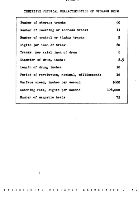
1.2.2 Physical charaoteristios. The physical oharacteristios of the
magnet-10 storage drum are listed· in Table I. Baokground material relative to the
mag-netic storage teohniques employed 1s contained in Reterences (d) and (e).
Non-return-to-zero signals, desoribed in these reterences, are used in the looator
tracks. Return-to-zero signals are employed in the storage tracks.
1.2.3
Funotional description. The tunctions ot the eleotrical parts ot thestorage seotion area (1) looating, (2) writing, and
(3)
reading.The problem of locating 1a to find the box on the magnetio drum oorresponding
to the address which has been set up in the Storage Addre8s Register (SAR. Figure
• l). The lei'tmst stage
ot
SAR selects the proper traok group. An ll-foldooin-cidence circuit oompares the settings of the other 11 stages with the outputs
ot
•
the amplitier oirouits which read the 11 looator traoks. When the ~ reaohe.
the angular position oorresponding to the addre.s oontained in SAR, the ooinoidence
oirouit generates a pulse. This pulse causes the
30
digits or a numbersimultane-oualy to be written into, or read trom. the selected one of the two groups of
traoks, at the correct angular position.
The writing system reoards on the drum digital intormation whioh has been .et
up in the storage Insertion Register and the Storage Blocking Register (SIR and
SBR, Figure 1). The number to be written into storage is received and held by SIR.
In aome operations of the computer, the writing ot certain speoified digits of the
number in SIR must be suppressed. This digit-blocking intormation 1s contained in
BBR •
Sixty writing eirouits drive the
60
magnetic heads associated with the storagee·
e
e
IBS
COMPUTER CHARACTERISTICS5
traoks. Eaoh writing oirouit oontains two miniature thyratron8, eaoh of which can
disoharge a 8 imple network through a winding on the _gnetic head. One thyratron
i8 tired to write a 1, the other to write a O. The thyratrons are triggered by the
locator ooinoidenoe 'pulse ga:ted through the proper group-selecting gate. One
ot
the tubes
(tor
suppressed digits, both tubes) is prevented from tiring byapplica-tion ot a negative bias to its shield grid. This type ot writing oirouit is
des-cribed in Referenoes (d) and (e).
The Storage Reading Amplifiers (Figur e 1) amplify the signals read from the
.elected group of storage traoks and cause the number read from a seleoted box to
be transmitted to a speoified destination in the computer. There are
30
readingt"
amplifiers, each having dual inp~ stages. One set of inputs is assooiated with
eaoh ot the two track groups. Which set is blocked and which i8 operable is de·
termined by the leftmost dig it in SAR.
The.e Storage Reading Amplifiers have thr •••• ts of output gat.s. The n~
ber being read may be directed to the X-Register. to the Program Control Registers
(CTS, PAR, BAR, in Figure 1), or to the Print/Punoh Register. The destination is
.elected by impressing the pulse trom the locator coincidenoe oirouit an the
ap-propriate set ot output gates. In the case ot reading data into the Print/Punch
Register, a lookout is provided against tilling the register unt il suoh time as
the information previously put into it has been consumed by the typewriter unit.
The address searoh preoeding eaoh writing or reading operation is initiated
by a signal from the Program Control Seotion ot the oomputer. Upon oompletion of
the writing or reading operat ion, an end-signal notifies Program. Control and
c18ar~ BAR, SIR, and SBR.
••
•
BBS COMPUTER CBARA£TERISTICS
6
1.,
Arithmetio Seotion.1.,.1
Component.. The prinoipal unitsot
the Arithmetic Seotion of the oom-puter are the X-Regi.ter (X), the Q-Register(Q),
and the Aooumulator (A). Allarithmetio operations are performed on number. oontained in these units. The a1m-pler arithmetio operations are direoted by the Program Control. Sequential
rou-tines (shift, IIIlltiply. divide) whioh are part of the 1JK)re complex arithmetio
prooe.ses are direoted by the Arithmetio Sequenoe Control.
ot
whioh the ArithmetioShirt Counter (ASK) 1s a oomponent unit. The avenues
ot
oommunioation betweenthese
am
other units or the oomputer are shown schematioally in Figure 1.1.3.2 Number representation. Binary numbers are used throughout the
comput-er. Jegative numbers are expressed as complements on (230_1) in the boxes of
storage, in X, and in Q. The.e lm,its are allot 3D-digit width. In A, whioh i •
60 digits wide, negative numbers are expressed as complements on (2
60
_1). Thisi. the familiar "ODe t I-complement" representati on. It is a property of this
rep-resentatiOl1 that the e%tram lett digit
ot
a pl siti ve nUDber 1s 0. that of aneg-ative number, 1.
The binary point is located at the right in all registers. That is, all
nua-bera are treated as integers by the m.ach ine. Ion-integer numbers _y be handled
by progranming soale f aotor 8.
To sUIJll1arize, registers other than A ... y oontain any posit ift or negative
in-teger whose absolute value does not exoeed (229_1). The Aooumulator (A) may
oon-tain any integer whose ,absolute value does not exceed
(~9_l).
1.3.3 AocUDIllator. The Aocumulator is the oentral theater of numerical
op-erations in the oomputer. In this unit, the sum, difference, product, or
remain-• der are formed, and numbers are manipulated in various ways.
••
•
NBS COMPUTER CHARACTERISTICS
The Aooumulator is basically subtractive. with end-around borrow. That 1a.
every number transmitt.d to A i8 automatioally aubtracted into (1 •••• 8ubtraoted
trom.) the number there. the new nUDi>er in A being the resulting differenoe. The
.ubtraction is performed modulo (260_1). A number may be added into A by
trane-m1 tting its oomplement to A.
There are two ways of representing zero in the one' a-oomplement number
ays-7
teuu (OOO ••• O) and (lll ••• l). An additive aooumulator can generate only the kind of zero (111 ••• 1) which has the maohine prop,erties of a negative number. A
sub-tractive aocUJIIllator oan generate only the kind
ot
zero (000 ••• 0) whioh has themaohine properties of a positive number. Apart from this exolusion of the
nega-tive zero, the question of Whether the aooumumulator is subtraotive or additive
i. an interna.l property of the me. ohine, and ne ed be
ot
no conoern to theprogram-mer.
The number in A mAy be shitted to the left by any number of places from 1 to
59,
in response to a single command. This shift i8 "oircular". i ••• , a digitahirt ing out of the lett end of A is not lost, tut shirts into the right end.
Eaoh single shift
is
mathemat1cally equivalent to mul tiplioation by 2, modulo(260_1).
The ACOUDlllator Input Gates shown in Figure 1 perform the oonvers ion of 3D-digit numbers from X or Q to the appropriate kind
ot
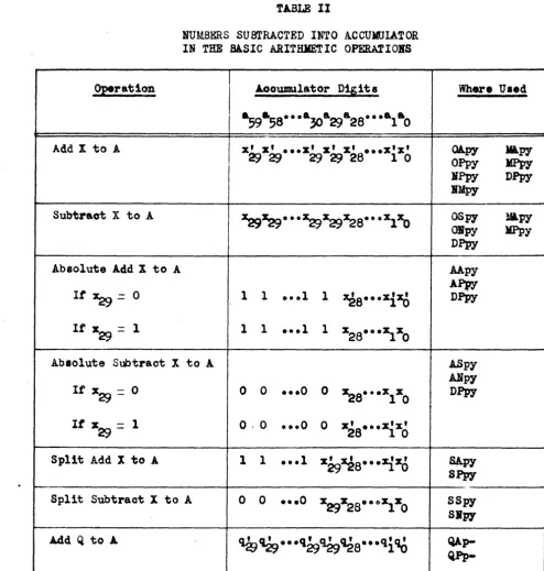
6o-digit number to be sub-traoted into the Aocumula.tor. The kinds of numbers whioh are subtraoted into Ain the various ari thmetio operations are tabulated in Table II, and will be
dis-oussed in Section
2.3.
1.3.4
Q-Register. The Q-Register participates in several arithmetic and • logical operations. These will be described in Chapter 2. In partioular, the••
•
•
ISS
COMPUTER CHARACTERISTICSquotient ia f'or_d in Q in division, and the multiplier he Id there during
DDllti-plioatio~ This register may also be used tor rapidly aoo.s8ible storage
ot
asingle number, since it communicates bilaterally with A.
By means
ot
a single OOJDDand, the number in Q may be 8hilied oiroularly tothe left trom 1 to 29 plaoes.
1.;.5
X-Register. The prinoipal funotion of X is to receive numberstrana-mitted from storage to the Arithmetic Seotion. This register has no adding or
shitting property. It is possible to subtract into A the number in X or Its
oom-p1ement. Addend. subtrahend, multiplicand, or divisor are held in X during the
oorresponding arithmetic operations.
1.,.6 Shift Counter. The Arithmetic Shift Counter (ASK in Figure 1) oounts
8
the number of plaoe. shifted in the several operations involving shifts of Q or A •
It is a subtraoti ve oounter whioh may be preset to the number
ot
plaoes it isde-aired to shift. Eaoh single-shift oontrol pulse subtracts 1 froa the oounter.
The arrival of ASK at zero outs
ott
the train of oontrol pul.e. and stopa theahi1'ting sequenoe.
The Arithmetio Shift Counter oounts modulo
60,
in that it resets to59
attero.
This property is used. in the 80ale factor shift, to be described in Chapter2. The output gates to SIR are inoluded solely tor the soale factor shift.
"
1.4
Program Control Seotion.1.4-1 Computer instruotiona. The ttmotion or the Program Control Section
ot
the computer is to direct the exeoution of a program of instructions, contained in
storage. tor the working
ot
a mathematical probleDMEach instruotion 1s expressed as an aggregate of 30 binary digits and nay be
stored and transmitted in precisely the same manner as a numerical quantity. The
.'
•
•
NBS COMPtJ'l'ER CHABACTERISTICS 9
right-hand 12 digits ot an instruotion represent y,' the exeoution address. This
is the address of the box in storage to which referenoe must be _de in order to
carry out the instruction. The mxt 12 digits to the left represent p, the
pro-gram address. This is the address of the box oontaining the next instruction in
the progr~ The lett-hand
6
digits express the command code. This codespeoi-fies which command, ot the ~ understood by the maohine, is to be exeouted.
Some of the commands do not require a referenoe to storage for executionJ for
these there is no associated execution address, and the right-hand 12 digits are
therefore irrelevant., In a few cases, these 12 digits contain specialized
infor-mationJ e.g., the number ot places that Q or A is to be shifted. The commands
will be discussed in Chapter 2.
1.4.2 COMponents. Program Control obtains each instruction in the program
from storage and translates it into oontrol pulses directed to various parts
ot
the oomputer in oorrect sequence tor its execution. An instruotion transmitted
trom storage to Program Control is split into three parts. The exeoution address
is reoeived in the Exeoution Address Register (EAR in Figure 1). the program
ad-dress in the Program Adad-dress Register (PAR), and the OOJlJDand code in the CoJDDand
Translator Switoh (CTS).
The ,Command Translator Switoh 1s a toggle-oirouit oontrolled diode matrix,
of the ~ desoribed in Referenoe
(t).
A given 6-digit oode set up in CTS ener-gizes one of a number of output leads (39 used. 64 possible). This d-o levelsignal seleots the set of basic operations appropriate to the speoified coamand.
These operations are sequenced by pulses from the pul8e generation and
distribu-tion units and associated connecting matrioes. (Theae unit. are shown in blook
form in Figure
3.)
ENGINEER I N a RESEARCH ASS 0 C I ATE S INC •
••
•
•
BBS COMPUTER CHARACTERISTICS 10
1.4,.
3
End Point Counter. The End Point Counter (EPK in Figure 1) i. a12-digit subtractive oounter whose primary purp08e i8 to OOtmt the number
ot
times arepetitive routine has been traversed in a program. The oounter i8 operated by
two speoia1 oOllUl8nds whioh will be dis cussed in Chapter 2. This unit also par-tioipates in the maohine input operati ems.
1.5 Input Section.
1.5.1 Input medium. The Input Section of the machine. transmits numerioal
data and the program
ot
instructions trom the input mdium to the storage system.. The input medium is 7-hole ptmohed taper tape. with data confined to six levels,or traoks. The seventh level is reserved for codes to control the input
oper-ationa •
Each 3D-digit box in storage is loaded from five oonseoutive lines on the
input tape. These five lines will be referred to as a -frame". The first line
ot
a trame corresponds to the Ie rtmost firthot
a bOlt. the seoond line to theseoond tifth, eto.
1.5.2
Tape reader. The tape is soanned by a photoeleotric readiDg deviceat a nominal speed
ot
75 teet per minute. This corresponds to 150 lines perS8C-ond. or 30 frames per seoond. It it should be desired to load the entire drum,
it would take about
2.,
minutes to till all 40}6 boxes.The magnetio drum rotates oontinuously at its normal speed during the input
operation.· The tape teed need not be synchronil ad with the drum rotation. It 1s
necessary only that the nwrber
ot
drum revolutions per second exoeed the nUJd:)erof tape frames scanned per second.
The tape is driven by friction rollers. moving oontinuously rather than
inter-~
mittently. The feed holes. normally used in sprocket-driven tape systems, are
•
•
NBS COMPUTER CHARACTERISTICS
11
scanned photoeleotrically to provide pulses tor timing the input oontrol oirouits.
1.5.3
Input control, oharaoteristics of. The information on the tape is ot two kinds, (1) data (numerical and program) to be written into storage) and (2)oodes for controlling the operat ion of the input seotion, but not to be written
into storage.
The fifth or last line ot each frame on the tape is aocompanied by a
seventh-level hole. This synchronizing hole is one form
ot
input control code. Inaddi-tlon, there are two basio oommands for oontrolling the tape-to-drum loading
opar-at ion. Eaoh sequenoe of dopar-ata frames is preoeded by a frame" containing an initial
address, plus a tape control code in the seventh level. Following the sequenoe
ot data frames there i8 a frame oontaining a check address, plus a different tape
control code in the seventh level. The two tape oontrol oommands are logioally
equivalent to the following s~atementsa
INSERT ADDRESS, Write the oontents
ot
the next frame of tape into the box speoified by this address, and oon-tinue to write the contents of suooeed:ing frames of tape into boxes of conseoutively asoending address.CHECK ADDRESS. Stop the loading sequence and oompare
the address given in this frame with the address (oontained in a counter) ot the box whioh was about to be loaded. It they are alike, oontinue .oanning tape for next sequenoe. If not, stop tape motion and flash alarm. (This oonmand stops the tape motion only i t an error is deteoted.)
Each sequence of data is preoeded by an INSERT ADDRESS oode. and is tollowed
by a CHECK ADDRESS oode. Several sequences ~ be spliced together, or punohed
on one tape. or ptmohed on ditt.~ent tapes. They may be loaded into the maohine
in any order.
1.5.4
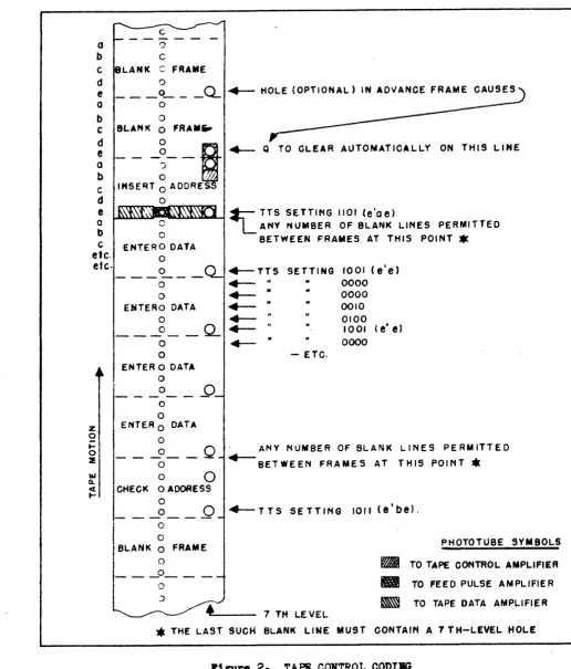
Input control, meohanism of. The appearance of the tape oontrolood-• ing is shown in Figure 2. A bank
ot
11 phototubes soans the tape as it travelse·
•
IBS COMPUTER CHARACTERISTICS 12
past the reading position. These are identified by the shaded blooks in the
dia-gram. Six of the phototubes read a single 6-digit line ot data. One phototttbe
views the teed holes. Four phototubes read the seventh-level oontrol oode.
Aa eaoh line of tape arrives at the horizontal bank: ot data phototubes. the
tour seventh-level tubes observe a binary oode (e.g., 1101 at the inatant shown)
whioh identities the procedure to be tollowed on that line. The five lines 00 . .
posing a frame are labelled a,b,c.d, and e. The positioning
ot
the controlphoto-tubes is such that when the data phototubes are viewing the e line, the oontrol
phototubes are viewing the e', a,b, and e positions in the seventh level. The
label e' reters to the e position in the preoeding trame. The e' and e oontrol
phototubes are energized simultaneously only .nen an e line is opposite the data
phototubes. That is, an • line is identified by a oontrol code ot the torm lXXl •
In partioular •. 1101 identities the e line ot an INSERT ADDRESS frame. 1001 the e
line of an :&}ITER DATA trame, and 1011 the e line of a CHECK ADIRESS tr8.D8.
Con-trol oode8 not of the form lXXl identity a, b, 0, and d lin ••
ot
.!!l
kind of frameJthese are all given identioal treatment. Instructions tor the tinal disposal
ot
a frame ot data are not revealed until the e line i8 read.
Figure
3
18 a blook diagram showing those partsot
the oomputer whichpar-ticipate in input operations. The digital transmission paths used in input
oper-ations are shown also in Figure 1.
The Tape Translator'Switoh (TTS) 1. a oonsiderably simplified version
ot
theCommand Translator Switch (CTS). One ot its five output leads is en.rgized on
reoeipt
ot
the 4-digit tape control oode. The outputs operate into the computer'.operation seleoting _trix, in the same manner as the outputs of CTS. All input
e
operations internal to the computer take place at the sa.me pulse rates as ine.
e
NBS eOUPOTER CHARAC'lERIST Ies
13
regular oomputing.
The Q-Register is used for assembling the five 6-digit lines
ot
a trame 01'tape, and tor providing part
ot
the "cushion" storage of data en route trom tapeto drum. The rapid shirting property of Q is utilized in the assembly operation. Atter the e line of a fram has been received by Q, the number in Q is trens-mitted to one of two destina.tions, depending on the ~
ot
f'rame being read, asidentified by TTS. If' the frame is of the ENTER DATA kind, the number iJl Q is transmitted to SIR for writing into storage. It it is either an INSERT ADIliESS
or a CHECK ADDRESS frame, the oomplement of the nUJli)er is transmitted to EPI
(right-band 12 digits only, other. being irrelevant).
The End Point Counter (EPK) i . utilized to ke.p track
ot
the addres. of thebox to be loaded. For maChine loading operations, this unit is provided with an
"AWe
n set of input terminals. A l2-digit number transmitted toBPI
via thesetar-minals is "added wi thout carry" to the number in BPI.
In Section 1.~3,
EPI
was described as a l2-digit subtractive counter. Forinput operations, it is required to ~ 1 to the addres8 in the counter for each
suocessi va trame of' data. The des ired properties are realized by inserting the
oomplement of the initial address in EPI, subtraoting 1 trom. this each time, and
transmitting the complement of the number in EPK to SAR. (This is equivalent to
relabelling EPK's input and output terminals).
The modus operandi of the input prooess will now be described (with the
le8-ser details omitted). As eaoh line of tape passes before the phototube., a sharp
pulse 1& deli~red by the Feed Pulae Amplifier. This pulse causes TTS and the
right-hand six stages
or
Q to be tilled tJ-om. the appropriate tape amplifierout-e
puts, and initiates a short, rapid .equence of 1r.tternal machine operations, a.E N S I N E E R ING RESEARCH ASS 0 C I ATE S I " C •
-e·
e
e
tollowsl
BBS C O.MPtJTEB. CHARACTERISTICS
It the TTS setting is not of the form lXXl, the line i. a,b,o, or d, and the principal operation 1s a 6-plaoe shift at Q.
It the 1'1'5 setting is 1101, the line 1s the e line
ot
an INSHtT ADDRESS trame, and Q is now full. First EPK 1s cleared to0'
8, then the complement output of Q 1s transmitted to theAWC input
ot
EPK. The number in EPK 18 now the complementot ..
the initial address.
It the TTS setting is 1001, the line is the e line
ot
an ENTER DATA trams, and Q is tulle The complement outputot
EPKia transmitted to SAR. This sets"UP the initial address in its norJDll form. The normal output of Q is transmitted to SIR. The Initiate Write control lin. to storage is pulsed. The Advanoe
EPK
line, which subtraots 1, is pul •• d. This sets upthe destination address tor the next frame.
If' the TTS setting is lOll, the line i& the e line
ot
a CHECK ADDRESS trame, and Q is tulle It the oheok is good, the numbers in Q and EPK are oomplements. The complement output of Q. is transmitted to the AWC inputot
EPI, as betor.. This leaves 0 t s in BPI. The Advanoe BPI line is pulsed. If' this operation produces an end-borroy~. check is good.14
So that orders
ot
magnitudeot
the time intervals involved may be fullyap-preciated, it should be noted that the feed pulse repetition period is extremely
long
(6700
microseoonds) relative to the internal olook pulse period(2.5
micro-seoonds).
1.5.5
Tape preparation unit. The input tape is prepared by means ot a speo-ial keyboard unit which actuates a standard 7-hol. tape punch. The keyboardar-rangement has not been atandardized at this writing. One suggested design has
two arrays of
64
keys eaoh. The keya in one group are marked with the octalnUB.-bare 00 through
71.
Thirty-nine of the keys in the other group are labelled withthe
39
command code symbols (OA, OP. TE. etc.). Eaoh key in one group il tiedeleotrically to one key in the other group. Depressing a given key sets up the
corresponding 6-digit binary number to be punohed as a line ot data. ·After the
e·
HSS COMPUTER CHARACTERISTICS15
number is set up, a Punoh
2
Advanoe bar is struok. There are two suoh bars.One ot these oauses the seventh-level hole to be inoluded, the other oauses it to
be omitted. It a speoial switoh is set, a seventh-level hole will automatically
be inoluded opposite every fifth, or e, line. Five lamps indioate whioh of the
five lines of a frame 18 about to be punohed.
1.6 Output Seotion.
The Output Seotion of the oomputer oontains means
tor
transmittinginforma-tion from storage to a punohed paper tape an~or a printed page. Two oommands, PRINT ONLY and PRINT AND PUlI;H, are provided tor governing the output operations.
These will be desoribed in Chapter 2.
Both ot these commands oause the right-hand six binary digits in·a specified
e
box in storage to be transmitted to the Print/Punoh Register (PPR in Figure I), a8 explained in Section1.2.3.
An. eleotrio typewriter then prints the oharacter.
to whioh this oode corresponds, and (if 80 instructed) a perforator punohes the
lix digits as a line
ot
data on 6- or 1-ho1e tape. As soon as the mechanioalop-eration ia under way, PPR olears and ~s reoeptive ~o further data.
Onoe a print operation haa been initiated, the oomputer is tree to oontinue
with its program. It is not neoessary tor Program Control to stop and await
oom-p1etion
ot
the printing operation. However, a seoond printing operation isauto-matioally delayed until oompletion of the previous one.
e
e·
NBS COMPUTER CHARACTERISTICS16
CRAPl'ER 2
COMPUTING aaARACTERISTICS
2.1 Introduotion.
The computer has a repertoire of
39
operation oommands. The§e oommands aredefined in Section 2.2, without elaboration. Comments on the commands are
con-tained in Seotion
2.3.
Factors influenoing the speed of computing are treated inSection
2.4.
2.2 Definitions of the Command ••
2.2.1 Nomenclature. In the 39 definition8 to follow, parentheses around an
e
addre8~ symbol or a register symbol mean "the number oontained in" the box or reg-ister so designatedJ e.g., (y) is the number in the box whose address is y. ande
(A) i. the number
in
the Aooumulator.The numbers oontained in A, Q, and X are expressed as aggregates ot digits ai' qi' and Xi' respeotively, where the subsoript "in is the power
ot
2 a88ooi~ted withthat digit. That is, aO is the coefficient of 2°, and is therefore the right-hand
digit of (A) J a i is the (i + 1 )th digit from the right.
A. coding designation is inoluded for eaoh command. (These oodes are repeated
in Table III, together with their mnemonic significance.) Eaoh double oapital let-'
ter should. be regarded as a single symbol. On the tape-preparing keyboard there rill be a key for eaoh of the
?B
symbols.Thi. set of oommands will be oalled List
E-4,
to distinguish it trom previou8-ly reported lists.2.2.2'" Prinoipal additive oOJllll8nd.. The following twelve statements define
e.
e
e
BBS COMPUTER CHARACTERISTICS 17
the ·ordinary". nab.olute". and "split" types
ot
additive command.1. 0A.py - HOLD ADDs Add (y) to (A.).
2. Oppy - CLEAR ADD. Clear A. and insert (y).
3.
OSpy - HOLD SUBTRACTs Subtract (y) trom (A).4.
ONpy - CLEAR SUBTRACT. Clear A and insert the negative of (y).5.
AApy - ABSOLUTE HOLD ADD. Add to (A) the absolute value ot(y).
6.
APPy - ABSOLUTE CLEAR AnDa Clear A and insert the absolute valueot
(y).7.
ASpy - ABSOLUTE HOLD SUBTRACT, Subtraot trom (A) the absolute value ot(y).
8. ANpy - ABSOLUTE CLEAR SUBTRACT. Clear A and insert the negative
ot
theabsolute value ot (y).
9.
SApy - SPLIT HOLD ADD. Add (y) to (A). exoept that 0'. are to be addedinto the lett-hand
30
plaoe. ot A.10. SPpy - SPLIT CLEAR ADD. Clear ·A. insert (y) into the right-hand
30
place ••
11. SSpy - SPLIT HOID SUBTRACT, Subtract (y) trom CA.}. exoept that O'a are
to be subtraoted into the left-hand
30
plaoesot
A.12. SNpy - SPLIT CLEAR SUBTRACT, Clear~. insert the negative ot (y) into
the right-hand
30·
plaoes. and insert lts into the left-hand30
plaoea.2.2.3
Misoellaneous Accumulator commands. The tollowing seven statementadetine additional oommands relating to transmission of data between A and storages
13. BPPy -
CLEAR ADD PLUS ONEs Clear A and insert (y)+
1.14-
NMpy - CLEAR ADD MINUS ONE. Clear A and insert (y) - 1.15.
lApy - HOLD LOGICAL MULTIPLY. "Split add" (y) to (A), as in SA.py, butsuppress the transmission to A
ot
those digitsot
(y) whioh are ine·
e
e
NBS COMPUTER CHARACTERISTICS 18
plaoes oorresponding to O'a in
(Q).
16. LPpy - CLEAR LOGICAL MULTIPLY, Clear A and insert (y) into the
right-hand
30
plaoes. but suppress the transmission to Aot
those digitsot
(y) whioh are in plaoe8 oorresponding to
0'.
in(Q).
17.
SDpy - SUBSTITUTE DIGIT S, Replaoe each digitot
(y) with the oorr ••-ponding digit ot (A). provided the oorresponding digit ot (Q) i8 a 1,
the remaining digits
ot
(y) are not to be disturbed.18. SEpy - SUBSTITUTE EXECUTION ADDRESS, Replaoe the right-hand 12 digit.
ot
(y) with the oorresponding digits ot (A). the remaining 18 digit.ot
(y) are not to be disturbed.
19.
AYpy - STORE A, Replaoe (y) with the right-hand30
digits of (A).2.2.4
Q-Register oommands. The following five oommands are related totransmission of data into and out ot Q.
20. YQpy - FILL Q. Clear Q and insert
(y).
21. AQp- - TRANSMIT A to Q. Clear Q and insert the right-hand
30
digits ot(A).
22. QAp- - HOLD ADD FROM Q, Add (Q) to (A).
23.
QPp- - CLEAR ADD FROM Q. Clear A and insert (Q).24.
QYpy - STORE Q. Replaoe (y) with (Q).2.2.5
Arit~tic sequence oommands. The tollowing six oommands are relatedto arithmetic proce •••• whioh'involve the Arithmetio Sequence Control.
25.
ALpk - SHIFT A LEFr. Shift (A) to the left k times. replaoing extr.meright digit with the one whioh was at extreme lett each time (ciroular
shirt ).
26. QLpk - SHIFT Q LEFT. Shift (Q) to the lett k times. replaoing extre.
e·
e
e
RBS COMPUTER CHARACTERISTICS 19
right digit with the one whioh was at extreme lett eaoh time (ciroular shift ).
27.
Mlpy - HOLD MULTIPLY. Add to (A) the productot
(Q) and (y), withoutroundoff, leaving multiplier intaot in Q.
28. JlPpy - CLEAR KTLTIPLY. Clear A. and insert the produot of (Q) and (y),
without roundoff, leaving multiplier intact in Q.
29.
DPpy - DIVIDE. Divide (A) by (y), putting the quotient in Q and leaving30.
a non-negative remainder, R, in A. The quotient and remainder are
de-tined by.
where
and
)I
=
QD+
R•
D
dividend (numerator)
divi80r (denominator).
(o~ R<IDI),
SFpy - SCALE FA.CTOR SRIF'l'. Shirt (A) oiroularly to the lef't until a
59
and a
58
beoome differentJ replaoe the right-hand 12 digitsot
(y) by aoharaoteristio, k, defined by.
k
=
(30 - S) mod 60 (0 ~ k ~59),where S is the number of plaoes shitted. It (A) consists of all
0'.
or all 1'8, reoord k a831.
2.2.6 Test oommands. The following tive atat.menta detine four test, or
discrim1natio~ oommands (PEpt is simply a preparatory operation
tor
TEp,y).31.
PBpt - PRESET END POINT COUNTBR. Clear BPK, insert the number t (thetotal number
ot
times a routine is to be traversed), and subtraot 1trom (EPK).
32.
fEpy - TEST ElfD POIft. Subtraot 1 trom (EPK), i t an end-borrow (ohangeot
sign) results, take (y) as the next instruotion, it not, take (p)•
•
•
BBS COMPUTER CHARACTERISTICS 20
aa the next instruotion.
;;. TFpy - TEST FULL ACCUMULATOR. I t a
59 and ~8 (ooeffioients of ~ and 2
58
in (A» are alike. take (p) as the next instruotionJ it different.take (y) as the next instruction.
34.
THpy - TEST HALF OVERFLOW, It&30
and a~ are alike, take (p) as thenext instructionJ if different, take (y) as the next instruction.
35.
TSpy - TEST SIGB. If (J..) is negative, take (y) as the next inatruotionJit (A) is positive or zero, take (p) a8 the next tnatruction.
2.2.7
Print and stop oommand80 The tollowiDg four commands are related tooutput and stop operation81
36.
POpy - FRIlI'1' OILY, Transmit to 6-digit Print/Punoh Register theright-hand 6 digits of (y). and cause electric typewriter to print the char~ aoter to which thi8 code oorresponds.
37.
PPpy - PRINT AID PUliCH., Same a8 POW, but in addition cauae perforatorto punch the 6 digits a8 a line of data on 6- or
7 ..
hole paper tape.;8.
ISp- - IITERMEDIATE STOP, Stop olock pulse generator and flash IITER-MEDIATE STOP signal.39.
'8-- - FIIAL STOP,
Stop olock pulse generator and flashFINAL STOP
signal.
2.; Comments on the Command ••
2.3.1
.umbers transmitted to Aocumulator. The numbers subtracted into A inthe several basio inter.nal arithmetio operations are reoapitulated in Table II.
The symbols are those defined in Seotion 2.2.1. The complement
ot
a digit iarep-re.ented by a primed symbolJ i.e.,
xi
mean. (1 - Xi) ••
•
IBS
COMPUTER CHARACTERISTICS 212.,.2 Principal additive commands. The tour ordinary addlti'Y8 coaoande and
the tour absolute additive oomnands baTe obvious purpose_ The tour split addltlTe
oommands are provided tor manipulating "multiple precisian- number., wn.re 30-digit
-portions
ot
multiple length numbers are stored in separate boxe ••2.'.3
Miscellaneous Aooumulator oommands. The commands CLEAR ADD PLUSOBI
and ClEAR ADD MIIUS OlE reduoe the number
ot
storage reterences required to changea number (e.g., a computational index or a .tored instruotion) by one unit.
The LOGICAL MULfIPLY and SUBSTITUTE DIGITS commands provide oonalderable
flex-ibility_ To illustrate one type
ot
applioation, t1 n 4-digit nWlbers and one10-digit number oould be stored together in each box, and yet be manipulated aa
though they were stored in separate boxe.. The .eleotive operator in
Q . .
y belett let up tor a long seri •• of ateps •
2.3.4
Q-Register commanda. The oomnands TR.UTSlIIT A TO Q, HOLD ADD FROII Q.and CLEAR ADD
FROM
Q enableQ
to be used for rapidly acc ••• ible storage ot a30-digit number.
2.'.5
Arithmetio sequence commands. A natural question relative to the twoSHIFT IEFT oOJlllDflnds
1..
What happens it k, the numberot
plaoe. to be shifted,is made greater tha.n 59 or 29 in ALpk or QLpk, respectively? The an .... r oan be
deduoed trom the properties ot ASK, as desoribed in Seotion
1.3.6.
The actualnumber
ot
pIa ces shifted is equal to the nUDi>er represented by the right-hand .1xdigits of k.
A- flow diagram of the algorithm followed by the Arithmetio Sequenoe Control
in exeouting the two MULTIPLY oODlmlda 1. given in Figure
4-
(The swito:n-likesymbols in this diagram indioate logical diohotomies, not aotual .witohes.) the
• .tepa imMediately preoeding and following the "ba.io .ultiply algorithm" are
•
•
JIBS COMPU'1'ER CHARACTERISTICS 22
oorreotions tor a negative multiplier. The step labelled "Part
I"
i8 required
.-only tor cumulative multiplioation.
A tlow diagram ot the DIVIDE algorithm is given in Figure
5.
The "basic di-vide algorithm", it performed alone, would result in a quotient and a remaindersatisfying the tollowing conditions. (1) quotient odd (i •••• q29¥ qO)J and (2)
absolute value or remainder less than ~ equal ~ that of divisor. The initial
and final oorreotive steps produce the positive remainder speoified in tlie
det-inition. In particular, a zero remainder is then represented as zero.
Prior to division, the dividend in A may be shifted to the left to provide the desired number ot signifioant figures in the quotient. A limitation on th18
preliminary shi:rt is ttBt the quotientJlDlst lie within the range of QJ i.e., its
absolute value must not exceed
(i29 -
1). In partioular, if the most .1gnlticant digitot
the divisor is x28' then the JOOst significant digit of the dividend should
li8 no further to th~ lett than
&55
(this is a sufficient, but not alwaya neo •• -sary.oondition).The oommand SCALE FACTOR SHIFT is a "subatitution" oommand. whioh makes it
poaaible to insert the oharacteri8tic, k, into a stored ALpk or QLpk instruction.
The definition ot k is suoh that i f the oorresponding "mantissa" ia read out of
storage and then shifted by ALpk. it will have been restored to its Griginal
po-sition with respect to the binary point.
2.
,.6
Test cOJlllllands. The OOllll1and. FRESE! END POINT COUNTER and TEST END§
POINT are provided tor oounting the number of times a repetitive sequenoe ofin-• at-
'
structions in the program has been traversed. It is initially tilled wit.h a num-ber, t. equal to the desired number ot traversals, by means ot the ~.truction • PEpt. The instruotion TEpy, following eaoh tra.versal, diminishes the count by•
•
•
DS COKPOTfi( CliARACTERIS!ICS
23
on. and pertor_ the teat. The two ooJlllllfUlda are detined eo that the te.t goe. iJ:a.
the P direotion (t - 1) ti • • , and goes in the y direotion the t - th time.
..
The oOlllllllnd TEST FULL ACCUMULATOR te.t. 1Ihether the moat .1gn1.f'ioant dig1t
ot
(.&.) i. at
-Sa.
The oOJDllalld TEST HALF OVERFLOW _y be u.ed tor .eterm1ning whethera aiQg1e additiTe operation has produoed an oTertlow into the lett halt ot A.
2.'.7
Print and .top oo=-nda.the
cODIIIands PRIIT OBLY and PRIlIT ABD PUBCHare both provided in order that intermediate oheok results and other oontrol
in-toration _y be printed by the typewriter without molesting "smooth oopy" being
ao0UDl11ated on the punched tape.
Two STOP oOl1llUUlds are provided so that the operator - 1 determ.ne whether the
maohine has stopped to permit inapeotion
ot
a printed inter_diate result. orwhether the problem is o~pletely tinished. In addition to the •• progr . . . . d .tope •
there are .eTeral alarm stope whioh are aotuated by' tault-deteotor oirouit ••
2.4
OperatingTt..
Consideration ••2.4:1 Programming
tor
_xi.,.
ettective oomputer speed. In order to alt.the most etfective use
ot
the two-address .ystemot
oommands, the programmer ~thave knowledge of the minimum allowable time intervals between varloua kinds
ot
reterenoe to storage. This intorat ion 18 given in Table III tor the y} oomputer
OOJDDmds.
Let pi be detined as the address
ot
the box oontaining the presentinstruo-tion. y. the execution address whioh 1s part of the present in.truotioD, and P.
the program addres8 in the present instruction (l.e., the addres8
ot
the boxcon-ta1ning the next instruotion). Then the meaning
ot
the tabulated quantities, C.i& that y should lie at leaat C I cella beyond pt. p ahould 11. at least C~ oella
p 1 fI~
beyond YJ and (tor oommands with no execution addre •• ) p should 11e at least C ,
P P
•
BDS COMPUTER CHARACTERISTICS.e11a beyond p'. These nwabers are given in deoia1 notation a~ are rounded. to
multiple.
ot 8.
Expr.ssed in octal notation. the •• multiple. are 10, 20,30.
eto.The m1n1aun inter'ftLls detined by the C' a apply only to the angular portion
ot
eaoh addreas (see Section 1.2.1). Suppose that pI i8 6123 (in ootal) and that the
inatruction 1s
aW.
Then y. the addr.ssot
the box oontaining the II1ltiplieand,should be no smaller than 6123 plua 10 (octal), or 6133. But box number 2133.
which is situated at the same angular position in the other track group, paase.
the magnetio heads 8illlUltaneou.ly with 6133. and therefore has equal atatus for
timing purpose8.
Should a shorter interval be programmed than that specified in the table, the
only efteot is a 108s
ot
operating t~. the inter .... l is automatieally lengthened• by the duration
ot
a oompl.te drum revolution, or 16 milliseoonds.As a further retinement, the programmer J'lJAy assUll8 that the dead time from
3171
to 0000, and trom7777
to4000.
is equivalent to4D
cell-periods.2.4.2
Storage lookout d.lays.an.
ot
the taotors taken into aOOOUZlt 111ak-ing up Table III is the cirouit reoovery time whioh DUst elapse between the ...
eral kinds
ot
magnetic drum storage reterence. Automatic lookout dela7s are builtinto the storage system controls tor this purpose. !hee. delay. preftnt a v i tiJ21
operation trom tollow1n& a pre~ous writing operation by
1.8.
than about 2000mi-ero.aoonda. a r.ading fro. following a pre~ous writing by le.8 than about 250
mi-oro •• conda, and either operation fro. following a reading by le.s than about 60
microsecond ••
-2.4.3
Clock pulse rate. The Clook Pulse Gearator. whioh tu.a the _inPro-gram Control and the Arithmetic Sequence Control, operates at a rate
ot
400.000• pulsea per aeoond. Thi. rate determine. (and ia equal to).
the
shifting rateot
QEII81NEER IIIG RESEARCH ASSOC IATES I II C •
-•
•
•
DS COMPUTER CHARACTBRI STI CS
and A. in places per aecoDd.
the
baaic addition ~ole inthe
Aooumulator 183
olock pul •• periods, or7.5
microseconds. That is.7.;
aioroaeoonda after tr8!l8Dd •• ionot
a nUJlber to A. a.eoond operation in A. suoh as-shitting, _1 be ordered. this interval allowa
suttioient tiD tor propagation
at
a 6o-plaoe borrow (extreme oase) in A.the t1Ja1ng
ot
the JlJL!IPLY and DIVIDI proo.saea, as directed by theArith-. Arith-. tic Sequence Control, 18 based on these shifting and addtng ratea.
2.4:4
Parallel 1Aternal operations. The interDal operations ordered by the Program. Control occur both in sequenoe and in parallel. Exeoutionot
theinstruo-tion JIlpy w1ll .er," to ll1uatrate. Firat. Part I
ot
the mltiply algorithm(rig-ure 4) 1a initiated. ai.aJ.ltaneoully with initiation
ot
the . . aroh in storagetor
tn.
sltiplicand. Upon ooaplationot
theae operation., Part II of the al,orithai. initiated, 8ia11taneously with initiation
ot
the aearch 1D atoragetor
thenext 1nltruotion in the progr ....
Ias COMPUTER CBARACTERISfICS
26
e.
MISCELLAlEOUS GEHBRAL COISIDBRAfIOBS
-,.1
Manual Controls.A number
ot
aanual controls are required tor starting andtor
servioing theoomputer. An initial starting control seta the Program Control registers to read
the first instruotion trom a certain box. say 0000. whioh i8 alwaY8 used to bold
the first instruction in the program. the .tarting oontrol alao pertor. hoh
routine tasks as olearing t aggle-cirouit reg18ters to their proper initial nate.
Controls are also provided tor running the Clook Pulae Generator at a
re-duo.4 rate. and tor single-stepping. The diatributian ot olook pula •• may be
in-e
t.rrupted and resumed .anually.,.2
Cheoking and Servioing.Elaborate means
tor
cheoking the operationot
the computer are Dot pro"9'i4ed.'lhe de.ign or the maohine permta the frequent running
ot
briet oheok probl . . .during the course of a long oomputation. the non-wlatile nature
ot
the data in.torage enables the retention of check problems in storage
tor
extended periods.!here are. however, oertain speoialized ohecks. such as the address cheok in the
maohine loading operation (Section l.5~).
To taoilitate servicing. neon lamps are provided tor indioating the .tate
ot
all toggle-oircui ts in the computer. It is theretore po.sible to single-pulae the
aohine and observe the aotion,
tor
example.ot
the ari t~tio units.All eleotronio unit. are divided into replaoeable plug-in chaeei, of
oonven-e
lent 81z8.•
BBS CO)lP(jtBi CHAllAC!BRISTICS;.3
lumber of Tubea.the
nWlli>er of tube envelopes 1D the entire oollPUter 18 estll1awcl at2500.
-•
28
r
---.*
TAPETRANSL SWITCH ( TTS - 4 DIGS.)
o
ICL
4
*
G
...---*
TAPE CONTROL AMPLIFIE RS
(4 DIGS.)
COMMAND TRANSL SWITCH
(CTS- 6 DIGS.)
o
IST ADDRI (SAR
-o
CL
PRO~
ADORE (PAR
-o
CL
COMMAND TRANSL SWITCH
(CTS- 6 DIGS.)
o
ISTORAGE AL.>L.>RESS REG. (SAR - 12 DIGS)
o
CL
PROGRAM ADDRESS REG. (PAR -12 DIGS,)
o I
UNITS MARKED ( * ) ARE USED E X C L U S I VEL Y FOR IN P 'J T
*
°E NO POINT COUNTER (E P K - 12 DI G S.l
o AWe
I
EXECUTION ADDRESS REG. (EAR -12 DIGS.)
o
1Z 0 - r-<{ n:: w a.. 0 ~ ::> Cl. ~ z 2 ~ c{ rl:: lJJ 0.. 0 x: LU ~ ::> a :l 0 (.) STORAGE BLOCKI'\JG REG. (SBR - 30 DIGS)
o
CL
I ARITHMETIC SHIFT COU~~TER
(A S K - 6 DIG S . )
o
1o
IQ-REGISTER (Q - 30 DIGS.)
o
I I I6 •
, - - . _ _ _ _ .--11-...., )
TAPE DATA
A~PLIFIERS
·ORAGE ;KI'lG REG.
- 30 DIGS.)
CL
I
ITHME TIC
T COUNTER
6 DIGS.) I
6
*
---,*
rAPE JATA 'LIFIERS
DIGS.)
STORAGE INSERTION REG. (SIR - 30 D'G~.)
o
CL
I ACCUMULATOR
(A-60DIGS.)
-(x- 30 GIGS'>
o 1
STORAGE I READI NG AMPLIFIERS
(30 DIGS,)
PRINT / PUNCH
REGISTER (PPR-6DIGS')
o
,