Electronic Voting Machine Using Finger Print Module
1
SrinivasaRaoMogalikuduru 2Kassahun Awoke Tebeje
Kombolcha Institute Of Technology, Wollo University, Ethiopia.
ABSRTACT
The secured electronic voting
machine using finger print module is the most widely deployed publicized biometrics for identification. This is largely due to its easy and cost effective integration in existing and upcoming technologies. The integration of biometric with electronic voting machine using iris undoubtedly requires less manpower, save much time of voters and personnel eliminate rigging, ensure accuracy, transparency and fast results in election. In this paper, a framework for electronic voting machine based on biometric verifications proposed and implemented. The proposed framework
ensures secured identification and
authentication processes for the voters and candidates through the use of fingerprint and iris biometrics.
Various types of verification process are used, most procedure are publican verified by the representative of candidates of competing parties. Recount is also possible if there is any fraud or error. Conventional voting systems are not efficient due to long period of preparation, bogus voting, include papers, punch cards, mechanical levers, optical scan machines. These systems are not efficient as they are conducted manually and therefore very often are not accurate. As a consequence, it is obligatory to carry the available voting through an electronic system.This project uses two power supplies, one is regulated 5V for modules another one is 3.3V for LPC2148. 7805 three terminal voltage regulator is used for voltage regulation.
Bridge type full wave rectifier is used to rectify the ac output of secondary of230/12V step down transformer.
I.INTRODUCTION:
The objective of voting is to allow voters to exercise their right to express their choices regarding specific issues, pieces of legislation, citizen initiatives, constitutional amendments, recalls and/or to choose their government and political representatives. Technology is being used more and more as a tool to assist voters to cast their votes. To allow the exercise of this right, almost all voting systems around the world include the following steps: voter identification and authentication, voting and recording of votes cast, vote counting, publication of election results
Voter identification is required
during two phases of the electoral process: first for voter registration in order to establish the right to vote and afterwards, at voting time, to allow a citizen to exercise their right to vote by verifying if the person satisfies all the requirements needed to vote (authentication).
analytical methods for fingerprint matching. As the criminal justice system evolved, there arose the need for criminals to be uniquely identified by some physically identifiable trait. Richard Edward Henry of Scotland Yard began using fingerprinting in 1901 and its success eventually lead to its increased use in the law enforcement field
The field of biometrics was formed and has since expanded on to many types of physical identification. Still, the human
fingerprint remains a very common
identifier and the biometric method of choice among law enforcement. These concepts of human identification have lead to the development of fingerprint scanners that serve to quickly identify individuals and assign access privileges. The basic point of these devices is also to examine the fingerprint data of an individual and compare it to a database of other fingerprints
Nearly everyone in the world is born with a fingerprint that is unique; a separate and comprehensively identifying attribute that sets us apart from the other 6.5 billon people that inhabit this world. It is because of this fact that the fingerprint has proven such a useful part of biometric security. The very reason that fingerprint scanners are useful can be found in this fact as well. However, this is far from the only reason they are used.
Another important reason
fingerprint scanners are used is, they provide a quick, easy, efficient, and secure measure through which, an individual with the proper access privileges can authenticate. The fingerprint of an employee for example, is stored in a database that the scanner queries every time it is used. There are two basic Boolean conditions the scanner then goes through when an individual‟s print is scanned. First, the print is usually searched for in a database of fingerprints, once it is
found it then looks at the print to see what access privileges are associated with the print and compares them to the access they are trying to gain. If everything checks out the subject is allowed access and they are not otherwise. In any case, a log of the event is usually stored for security purposes the size of these devices is another reason they have become so mainstream recently. Fingerprint scanners can be deployed directly near a door for access or as a peripheral to a computer for logging in. Modern day scanners have even been embedded on computer keyboards, mice, and USB devices because engineers have been able to reduce their size. Fingerprint scanners are also very versatile in the function that they can serve. The most common use may be for access restriction; however, they have served as time clocks, personal data retrievers, and even to cut down on truancy in some schools. Since they have experienced so much success in these areas, businesses are expanding upon their use and they are getting more public exposure
II. LPC2148 (ARM7) Microcontroller
The LPC2148 microcontrollers are based on a 32 bit ARM7TDMI-S CPU with real-time emulation and embedded
trace support, that combines the
microcontroller with embedded high speed flash memory of 512 kB. A 128-bit wide memory interface and a unique accelerator architecture enable 32-bit code execution at the maximum clock rate. For critical code size applications, the alternative 16-bit Thumb mode reduces the code by more than 30 % with minimal performance penalty.
Due to their tiny size and low
power consumption, LPC2148
microcontrollers are ideal for the
point-of-sale. A blend of serial communications interfaces ranging from a USB 2.0 Full Speed device, multiple UARTS, SPI, SSP to I2Cs and on-chip SRAM of 8 kB up to 40 kB, make these devices very well suited for communication gateways and protocol converters, soft modems, voice recognition and low end imaging, providing both large buffer size and high processing power. Various 32-bit timers, single or dual 10-bit ADC(s), 10-bit DAC, PWM channels and 45 fast GPIO lines with up to nine edge or level sensitive
external interrupt pins make these
microcontrollers particularly suitable for industrial control and medical systems.
Figure 1:LPC2148 block diagram
III.Power supply:
The power supplies are designed to convert high voltage AC mains electricity to a suitable low voltage supply for electronics circuits and other devices. A power supply can by broken down into a series of blocks, each of which performs a particular function. A d.c power supply which maintains the output voltage constant irrespective of
a.cmains fluctuations or load variations is known as “Regulated D.C Power Supply”
Fig 2:Block Diagram of Power Supply
TRANSFORMER
A transformer is an electrical device which is used to convert electrical power from one Electrical circuit to another without change in frequency.
When AC is applied to the primary winding of the power transformer it can either be stepped down or up depending on the value of DC needed. In our circuit the transformer of 230v/15-0-15v is used to perform the step down operation where a 230V AC appears as 15V AC across the secondary winding. One alteration of input causes the top of the transformer to be positive and the bottom negative.
isolation between the power source and power supply circuitries.
Fig 3: Electrical Transformers
IV.GSM MODULE
GSM (Global System for Mobile
Communications,
originally GroupeSpécialMobile), is a
standard developed by the European
Telecommunications Standards
Institute (ETSI) to describe the protocols for
second-generation (2G) digital cellular
networks used bymobile phones, first
deployed in Finland in July 1991.[2] As of
2014 it has become the de facto global standard for mobile communications - with over 90% market share, operating in over 219 countries and territories.2G networks developed as a replacement for first generation (1G) analog cellular networks, and the GSM standard originally described a digital, circuit-switched network optimized
for full duplex voice telephony. This
expanded over time to include data communications, first by circuit-switched transport, then by packet data transport via GPRS (General Packet Radio Services) and EDGE (Enhanced Data rates for GSM Evolution or EGPRS).
Subsequently, the 3GPP developed third-generation (3G) UMTS standards followed
by fourth-generation (4G) LTE
Advanced standards, which do not form part of the ETSI GSM standard.
"GSM" is a trademark owned by the GSM Association. It may also refer to the (initially) most common voice codec used, Full Rate.
GSM networks operate in a number of different carrier frequency ranges (separated
into GSM frequency ranges for 2G
and UMTS frequency bands for 3G), with most 2G GSM networks operating in the 900 MHz or 1800 MHz bands. Where these bands were already allocated, the 850 MHz and 1900 MHz bands were used instead (for example in Canada and the United States). In rare cases the 400 and 450 MHz frequency bands are assigned in some countries because they were previously used for first-generation systems.
Most 3G networks in Europe operate in the 2100 MHz frequency band. For more information on worldwide GSM frequency usage, see GSM frequency bands.
Regardless of the frequency selected by an operator, it is divided into timeslots for individual phones. This allows eight full-rate
or sixteen half-rate speech channels
per radio frequency. These eight radio timeslots (or burst periods) are grouped into a TDMA frame. Half-rate channels use alternate frames in the same timeslot. The
channel data rate for all 8
channels is 270.833 kbit/s, and the frame duration is 4.615 ms.
The transmission power in the handset is limited to a maximum of 2 watts in GSM 850/900 and 1 watt in GSM 1800/1900.
V.GPS
The Global Positioning
States government and is freely accessible to anyone with a GPS receiver.
The GPS program provides critical
capabilities to military, civil and commercial users around the world. In addition, GPS is the backbone for modernizing the global air traffic system.
In addition to GPS, other systems are in use or under development. The Russian Global Navigation Satellite System (GLONASS) was in use by only the Russian military, until it was made fully available to civilians in 2007. There are also the planned European Union Galileo positioning system,
Chinese Compass navigation system,
and Indian Regional Navigational Satellite System.
VI.RS232 CABLE:
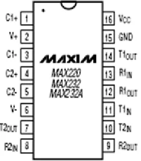
To allow compatibility among data communication equipment, an interfacing standard called RS232 is used. Since the standard was set long before the advent of the TTL logic family, its input and output voltage levels are not TTL compatible. For this reason, to connect any RS232 to a microcontroller system, voltage converters such as MAX232 are used to convert the TTL logic levels to the RS232 voltage levels and vice versa.
MAX 232:
Max232 IC is a specialized circuit which makes standard voltages as required by RS232 standards. This IC provides best noise rejection and very reliable against discharges and short circuits. MAX232 IC chips are commonly referred to as line drivers.
Fig 4: Pin diagram of MAX 232 IC
Of the four serial modes, only mode 1 is widely used. In the SCON register, when serial mode 1 is chosen, the data framing is 8 bits, 1 stop bit and 1 start bit, which makes it compatible with the COM port of IBM/ compatible PC‟s. And the most important is serial mode 1 allows the baud rate to be variable and is set by Timer 1 of the 8051. In serial mode 1, for each character a total of 10 bits are transferred, where the first bit is the start bit, followed by 8 bits of data and finally 1 stop bit.
VII.BUZZER DRIVER CIRCUIT:
Digital systems and microcontroller pins lack sufficient current to drive the circuits like relays, buzzer circuits etc. While these circuits require around 10milli amps to be operated, the microcontroller‟s pin can provide a maximum of 1-2milli amps current. For this reason, a driver such as a power transistor is placed in between the microcontroller and the buzzer circuit.
P1.0=1 (>0.7V), the transistor will be switched on and thus the buzzer will be ON.
When the voltage at the pin P1.0 is low i.e., P1.0=0 (<0.7V) the transistor will be in off state and the buzzer will be OFF. Thus the transistor acts like a current driver to operate the buzzer accordingly.
Switch :
A switch is an electrical component that can break an electrical circuit, interrupting the current or diverting it from one conductor to another. A switch may be directly manipulated by a human as a control signal to a system, or to control power flow in a circuit.
A simple switch has an open state and closed state. However, a microcontroller needs to see a definite high or low voltage level at a digital input. A switch requires a pull-up or pull-down resistor to produce a definite high or low voltage when it is open or closed. A resistor placed between a digital input and the supply voltage is called a "pull-up" resistor because it normally pulls the pin's voltage up to the supply.
VIII. RESULT:
The EVM consist of a controller and switching units, both the units are working independently collaboration with each other as well the control unit accept in finger print is enrolling mode and responding the accordingly the identify and vote casting
mode the control unit check for finger print detection routine
In total the complete system is working as for the initial specification and requirement of our project Because of the creative nature of the design and due to lack of time some features could not be fine tuned and are not working properly So, certain accept as the system can be modified operational experience is gained with it as the users work with the system with a develop varies ideas for the developing and enhancement of the project.
Power supply
Give the finger print and poling
Select the party
party 2 selected
Party 2 conformed
IX. CONCLUSION:
For over a century, fingerprints have been one of the most highly used methods for human recognition; automated biometric systems have only been available in recent years.This work is successfully implemented and evaluated. The arrived results were significant and more comparable. It proves
the fact that the fingerprint image
enhancement step will certainly improve the verification performance of the fingerprint
based recognition system. Because
fingerprints have a generally broad
acceptance with the general public , law enforcement and the forensic science community, they will continue to be used with many governments„ legacy systems and will be utilized in new systems for evolving applications that require a reliable biometric.
Thus the advent of this biometric voting system would enable hosting of fair elections in India. This will preclude the illegal practices like rigging. The citizens can be sure that they alone can choose their leaders, thus exercising their right in the democracy
X. FUTURE ENHANCEMENT:
module can be expanded .We can use a 1mb flash memory finger print module for increasing the capacity. 3.External memory can be provided for storing the finger print image, which can be later accessed for
comparison. 4.Audio output can be
introduced to make it user friendly for
illiterate voters. Unique Identification
Numbers (Aadhar cards) have already been introduced in India that contains an individual„s fingerprints and iris scan. Soon every Indian citizen can have a similar identity card and all the government will have all the necessary information required to bring such a system in play.
REFERENCES
[1]
http://wikipedia.org/wiki/Bharat_Stage_emi ssion_standards.
[2] George F. Fine, Leon M. Cavanagh, Ayo Afonja and Russell Binions " Metal Oxide
Semi Conductor Gas Sensors in
Environmental Monitoring", Sensors 2010, 10, 5469-5502; doi:10.3390/s100605469. [3] K. Galatsis, W. Wlodarsla, K. Kalantar-Zadeh and A. Trinchi, " Investigation of gas sensors for vehicle cabin air quality monitoring,” vol. 42, pp. 167-175, 2002. [4] “Trade of Motor Mechanic”; Module 5; Unit 2 Electronic Fuel injection; Phase 2 by FÁS Learning Innovation Unit with Martin McMahon & CDX Global; Curriculum Revision 2.2 16 01-07.
[5] LIU Zhen-ya, WANG Zhen-dong, CHEN Rong, “Intelligent Residential Security Alarm and Remote Control System Based On Single Chip Computer,” vol. 42, pp. 143-166, 2008.
AUTHORS:
SRINIVASA RAO MOGALIKUDURU ,mail id:
[email protected], KOMBOLCHA INSTITUTE OF TECHNOLOGY, WOLLO UNIVERSITY, ETHIOPIA.
KASSAHUN AWOKE TEBEJE,
mail Id:[email protected],KOMBOLCHA