Design coding format for optical fiber communications
Wail Y. NassirP
1
P
, Ali H. AbdulhadiP
2
P
, Hayder T. AssafliP
3
P
, Aseel A. ShakatyP
4
P
Laser and Optoelectronics Engineering Department, University of Technology, Baghdad, Iraq.
Abstract
A lot of application needs optical transmission signals. This interesting project presents a mechanism to transmit and receive laser signals on optical fiber. All digital communication systems have electronic circuits called encoder and decoder. The encoder circuit coded the coming data from information source and gave it to the transmitter. There is many types of encoders like non-return to zero (NRZ), return to zero (RZ). The decoder circuit decoded the received data from receiver and convert it to same transmitted data. In this project the format coder and decoder circuits (NRZ and RZ) was designed by using electronic circuit hardware and analysis software. Then was built the electronic circuit on board and test it experimentally.
Introduction
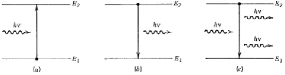
Optical fiber communication is a method of transmitting information from one place to another by sending pulses of light through an optical fiber. The light forms an electromagnetic carrier wave that is modulated to carry information. First developed in the 1970s, optical fiber communication systems have revolutionized the telecommunications industry and have played a major role in the advent of the Information Age. Because of its advantages over electrical transmission, optical fibers have largely replaced copper wire communications in core networks in the developed world [1]. The process of communicating using optical fibers involves the following basic steps: Creating the optical signal involving the use of a transmitter, relaying the signal along the fiber, ensuring that the signal does not become too distorted or weak, receiving the optical signal, and converting it into an electrical signal [2]. Under normal conditions, all materials absorb light rather than emit it. The absorption process can be understood by referring to Fig. 1, where the energy levels E1 and E2 correspond to the ground state and the excited state of atoms of the absorbing medium. If the photon energy hυ of the incident light of frequency υ is about the same as the energy difference Eg = E2−E1, the photon is absorbed by the atom, which ends up in the excited state. Incident light is attenuated as a result of many such absorption events occurring inside the medium [3].
Fig. (1) Three fundamental processes occurring between the two energy states of an atom: (a) absorption; (b) spontaneous emission; and (c) stimulated emission.
The excited atoms eventually return to their normal “ground” state and emit light in the process. Light emission can occur through two fundamental processes known as spontaneous
emission and stimulated emission. Both are shown schematically in Fig. 1. In the case of spontaneous emission, photons are emitted in random directions with no phase relationship among them. Stimulated emission, by contrast, is initiated by an existing photon. The remarkable feature of stimulated emission is that the emitted photon matches the original photon not only in energy (or in frequency), but also in its other characteristics, such as the direction of propagation. All lasers, including semiconductor lasers, emit light through the process of stimulated emission and are said to emit coherent light. In contrast, LEDs emit light through the incoherent process of spontaneous emission [4].
Transmitter
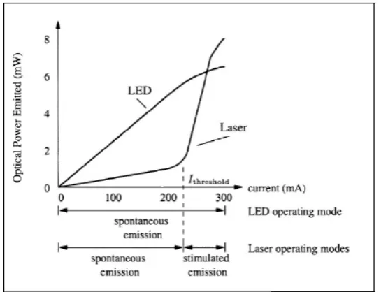
In principle, any light source could be used as an optical transmitter. In modern laser communication systems There are two type of optical light sources, such as Light emitting diode (LED) that give incoherent communication system. LED is a semiconductor device that emits incoherent light when an electric current passes through it. The light is low power and monochromatic, occurring at a single wavelength. The output from an LED can range from red (at a wavelength of approximately 700 nanometers) to blue-violet (about 400 nanometers). Some LEDs emit infrared (IR) energy (830 nanometers or longer); such a device is known as an infrared emitting diode (IR). An LED or IR consists of the P-N junction, LED is based on the semiconductor diode. The light is generate by spontaneous emission process When the diode is forward biased. The I-P characteristics of the LED can be show in figure (2) [5]. Such as laser diode (LD) that give coherent communication system. Laser diode, also known as an injection laser, is a semiconductor device that produces coherent radiation (in which the waves are all at the same frequency and phase) in the visible or infrared (IR) spectrum. Laser diode similar to LED, it is formed from a p-n junction with forward biased and powered by injected electric current, where the optical power is created. As the current exceeds the threshold, the forward current and optical power are directly proportional [3].
Fig. (2) Laser diode and light emitting diode P-I characteristics.
Semiconductor lasers emit light through stimulated emission. As a result of the fundamental differences between spontaneous and stimulated emission, they are not only capable of emitting high powers (≈ 100 mW), but also have other advantages related to the coherent
nature of emitted light. A relatively narrow angular spread of the output beam compared with LEDs permits high coupling efficiency (≈ 50%) into single-mode fibers. A relatively narrow spectral width of emitted light allows operation at high bit rates (≈ 10 Gb/s), since fiber dispersion becomes less critical for such an optical source. Furthermore, semiconductor lasers can be modulated directly at high frequencies (up to 25 GHz) because of a short recombination time associated with stimulated emission. Most fiber-optic communication systems use semiconductor lasers as an optical source because of their superior performance compared with LEDs. In this section the output characteristics of semiconductor lasers are described from the standpoint of their applications in light wave systems [6].
Receiver
The basic optical receiver converts the modulated light coming from the optical fiber back into a replica of the original signal applied to the transmitter. The detector of this modulated light is usually a photodiode of either the PIN or the Avalanche type. This detector is mounted in a connector similar to the one used for the LED, VCSEL or LD. Photodiodes usually have a large sensitive detecting area that can be several hundred microns in diameter [7]. This relaxes the need for special precautions in centering the fiber in the receiving connector and makes the “alignment” concern much less critical than it is in optical transmitters. Since the amount of light that exits a fiber is quite small, optical receivers usually employ high gain internal amplifiers. Because of this, for any given system, it is important only to use the size fiber specified as appropriate. Otherwise, overloading of the optical receiver may occur [8].
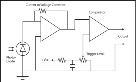
Fig. (3) Basic Analog Fiber Optic Receiver
Fig. (4) Basic Digital Fiber Optic Receiver
As in the case of transmitters, optical receivers are available in both analog and digital versions. Both types usually employ an analog preamplifier stage, followed by either an analog or digital output stage (depending on the type of receiver). Additional stages are often added to both analog and digital receivers to provide drivers for coaxial cables, protocol converters or a host of other functions in efforts to reproduce the original signal as accurately as possible [9].
It is important to note that while fiber optic cable is immune to all forms of interference, the electronic receiver is not. Because of this, normal precautions, such as shielding and grounding, should be taken when using fiber optic electronic components [10].
Results
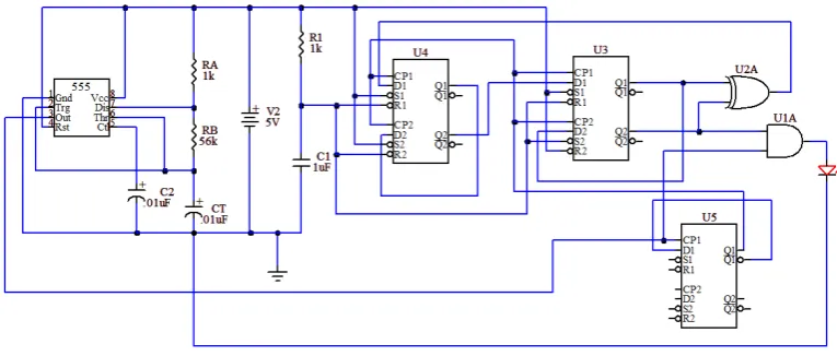
In order to do the job, a proposed circuit diagram was introduced. The receiving unit starts with the detector and ending with the oscilloscope. To start the project, the transmitter unit was built using the circuit diagram of figure (5) as an initial circuit.
This circuit was implemented in the lab. as a first stage of the whole proposed circuit diagram. The signal (square wave) was generated by using IC 555 with frequency 1.25 kHz, and feeding it the circuit and watching its way at through the laser diode.
Fig. (5) Transmitter Circuit
Figure 6 (a) illustrates the NRZ output and (b) illustrates the RZ for the above circuit.
(a) NRZ
(b) RZ
Fig. (6) Output of transmitter
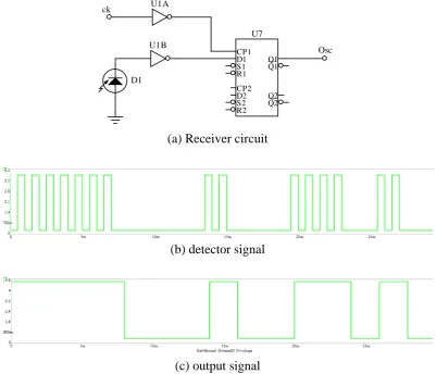
The Receiver has a detector (photodiode detector), which produces a pulse of electricity every time light lands on it. The cell is designed to pick up the particular frequency of light produced by the transmitter, so it is not disturbed or thrown off by other light. The signal was received RZ turns them into NRZ signal by using D flipflop. The receiver circuit is shown in figure (7).
(a) Receiver circuit
(b) detector signal
(c) output signal
Fig. (7) The receiver circuit
Conclusions
The main idea of the project was to design coding format for optical fiber communications which can be used for data transmission and reception. Through the whole work a transmitter circuit was designed and implemented using figure (5). It is output was demonstrated on figure (6). Then receiver circuit was designed and implemented as shown in figure (7). Laterally the whole project was integrated to work together with an analog input such as DC signal. It is coverage not more than a meter, because of using digital signals without lenses.
References
[1] 39THofmann, E. E. Basch, S. Gringeri, R. Egorov, D. A. Fishman, and W. A. Thompson,
“DWDM Long Haul Network Deployment for the Verizon GNI Nationwide Network,” Proc. Optical Fiber Communication Conf. Vol. 2, (2005).
Osc
D1 ck
CP1 D1 S1 R1 CP2 D2 S2 R2
Q1 Q1 __
Q2 Q2 __
U7 U1B
U1A
[2] 39TS. Arefin, "Performance Evaluation of a SCM Optical Transmission System", IOSR
Journal of Engineering, Vol. 3, 2013
[3] M. Schwartz, Information Transmission, Modulation, and Noise, 4th ed., McGraw-Hill, New York, 1990.
[4] A. Hasegawa and Y. Kodama, "Solitons in Optical Communications", Clarendon Press, Oxford, 1995.
[5] Steve Hranilovis , “Wireless optical communication system” , springer, Inc, Boston, 2005.
[6] O. Ueda, "Reliability and Degradation of Optical Devices", Artec House, Boston, 2006.
[7] Gerd Keiser, “ Optical Fiber Communication ”, McGraw-Hill, 4th edition, 2010.
[8] David A. Johnson, "Optical Through The Air Communications Handbook", Imagineering E-Zine, 2008.
[9] Y. Yamamoto, "Receiver Performance Evaluation of Various Digital Optical Modulation-Demodulation Systems ", IEEE Journal of Quantum Electronics, 2000. [10] J. G. Proakis, Digital Communications, 3rd Edition, McGraw-Hill, 1994.