IJEDR1602006
International Journal of Engineering Development and Research (www.ijedr.org)39
Microstrip Antenna Design with Parallel Rectangular
Open Slots Structure for Multiband Operation
Hazel Thomas
M.Tech in Communication Engineering SCMS School of Engineering and Technology
Ernakulam, Kerala, India
________________________________________________________________________________________________________
Abstract - The proposed antenna design consists of three parallel rectangular open slots (PROSs), etched on the ground plate of the microstrip antennas which can be used for multi-band applications. By employing the trial and error method to optimize the size and position of the PROSs, the reflection coefficient less than -10 dB at the Global Positioning System (GPS), Global System for Mobile communications (GSM) ,Wireless-Fidelity (Wi-Fi) and Worldwide Interoperability for Microwave Access (WiMAX) bands, can be achieved. To evaluate performance of the proposed PROSs structure, three antennas say Ant I(triple-band antenna),Ant II(triple-band antenna) and Ant III (four-band antenna) are designed . The simulated results of the three antennas, show good impedance matching and nearly omnidirectional radiation patterns.
Index Terms—PROS, multiband operation, trial and error method.
I.INTRODUCTION
With the rapid development of the modern wireless communications, such as GSM of 1.8/1.9 GHz, GPS of 1.227/1.575 GHz, Wi-Fi of 2.4–2.484 GHz (IEEE 802.11 b/g)/5.15–5.825 GHz (IEEE 802.11a) and WiMAX of 2.3/3.3/5.25–5.85 GHz, the need for multi-band antenna has gained much attention since it is more practical for a single system to support multiple communication standard simultaneously. Moreover, system compactness such as low-profile, lightweight and single-feed is also desirable to fit the limited equipment space of GPS, GSM,Wi-Fi and WiMAX devices. Hence, the microstrip antennas become good candidates to meet such requirement, and a lot of work has been reported on modelling the band printed antennas. Generally, multi-band performance is realized by different resonating structure or resonator in the antenna. The resonance usually can be generated through loading the different resonating patches or etching various slots in the microstrip antenna.
Of course, other structures also can be used to realize the band performance.However, such antennas achieve multi-band performance often using different or complex structures, which makes the design more uncertain and difficult. The study of a simplex structure to achieve multi-band operation certainly at any given frequency is practical. Furthermore, the antennas mentioned above are accomplished using trial and error method. To facilitate the antenna design process, the trial and error method made available through the software HFSS 13.0 to optimize our designs.
This paper presents three PROSs for the printed antenna to achieve multi-band performance. To further verify the function of the three PROSs, we demonstrate a triple-band antenna (Ant I & Ant II) and a four-band (Ant III) which satisfy GPS/GSM/Wi-Fi/WiMAX applications. Of course, other operating bands can be selected as you will, here, the selected bands are only an example to demonstrate the performance of the PROSs in the multi-band antenna design. Ant I,Ant II and Ant III are designed and implemented by loading PROSs with proper width at proper location in the ground plane.The parameters such as impedance bandwidths and radiation patterns were presented and discussed to validate the design methodology.
II. LITERATURE REVIEW
Multi-band performance is realized by different resonating structure or resonator in the antenna. The resonance usually can be generated through loading the different resonating patches or etching various slots in the printed antenna.Other structure also can be used to realize the multi-band performance.
Compact tri-band metamaterial-inspired antenna based on CRLH resonant structures :A single-cell tri-band composite right/left-handed (CRLH) resonant antenna is presented. The antenna is designed on a single-layer coplanar waveguide-fed based on the T-junction discontinuity equivalent circuit. The proposed antenna provides compact size, easy fabrication process, multi-band feature and higher efficiency in comparison with the previously reported CRLH resonant antennas[3].
© 2016 IJEDR | Volume 4, Issue 2 | ISSN: 2321-9939
IJEDR1602006
International Journal of Engineering Development and Research (www.ijedr.org)40
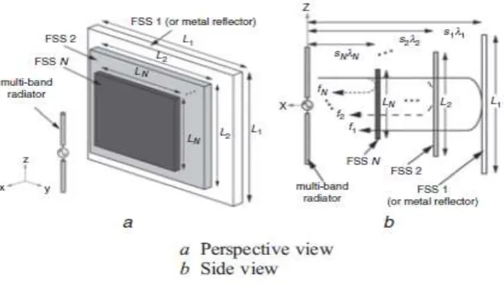
Figure 1: Geometry of monopole antennaDirectional multi-band antenna employing frequency selective surfaces : Proposed is a concept of a directional multi-band antenna employing frequency selective surfaces (FSSs). To confirm the feasibility of the concept, the proposal is implemented by combining a metal reflector, two FSSs that act as frequency filters, and a multi-band radiator. The proposed triple-band antenna can radiate at 800 MHz (the metal reflector or FSS 1), 2 GHz (FSS 2), and 4 GHz (FSS 3). FSS 2 passes waves at one frequenc y band (800 MHz) and reflects all other bands, and FSS 3 passes waves at two frequency bands (800 MHz/2 GHz) and reflects all other bands. Beam control is easy since all that is needed is to change FSS size and/or the distance between the radiator and metal reflector/FSS[5].
Figure 2: Concept of multi-band antenna employing FSS
IJEDR1602006
International Journal of Engineering Development and Research (www.ijedr.org)41
Figure 3: Schematic configuration of the proposed triple-frequency monopole antenna with defected ground structureHowever, these antennas achieve multi-band performance often using different or complex structures, which makes the design more uncertain and difficult. The study of a simplex structure to achieve multi-band operation certainly at any given frequency is practical.Our proposed system is designed for attain these requirements,that is simplex structure for multi-band operation[1].
III. ANTENNA STRUCTURE
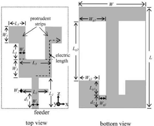
For the design here, the radiator and the ground plane are etched on the opposite sides of an FR-4 substrate (thickness of 1 mm, dielectric constant of 4.4 and loss tangent of 0.002). To simplify the design consideration, the width of feed line is designed of 2 mm to obtain 50 Ω impendence. Figure 1 depicts the prototype of the proposed multi-band antenna with parameters.
(a) Front view; (b) Side view; (c) Back view
Figure 4: Configuration of proposed multi-band antennas
In this study, we adopt three PROSs to achieve the multi-band performance. As a versatile structure of the patch, the PROSs can provide impedance matching for the different modes excited by the radiator. The three slots of the proposed PROSs are chosen to have a proper width and position for widening the band-widths of the antenna’s operating bands. Here, the width and position of PROSs are represented by parameters (L1-L6), and change of each parameter influences the PROSs structure. What is more, the width L7 of the radiating element also has an remarkable impact on the impedance matching of these three PROSs, thus L7 is included in the optimized parameters. The overall size (L8 and W1) of the proposed antenna shall be adjusted accordingly.
The spacing (L2, L4 and L6) of the three PROSs can also determines the lengths of the proposed antennas, so the coupling in the space between PROSs should also be considered.
© 2016 IJEDR | Volume 4, Issue 2 | ISSN: 2321-9939
IJEDR1602006
International Journal of Engineering Development and Research (www.ijedr.org)42
Table 1 : Dimensions of propsed AntennasParameters(mm) L1 L2 L3 L4 L5 L6 L7 L8 W1
Ant 1 3.6 0.4 2.5 19.4 1 0.7 2 43.6 18.6
Ant 2 4.0 1.0 4.0 1.0 4.0 1.0 4.0 50.0 20.0
Ant 3 2.1 13.8 3.2 3.6 1.2 5.7 5.8 50.4 31.4
We can see from Table 1 that the length of the antennas is smaller than half of is the mediumWavelength) which is due to the strong higher order mode coupling effects among PROSs. It also can be seen from Table 1 that different multi-band antennas with different resonating frequencies can be designed when the three PROSs and other parameters changed.
IV. SIMULATION MODEL
Antenna 1(tri-band antenna):
Figure 5 : Design of Antenna 1 in HFSS Table 2 : Dimensions of Antenna 1
Parameters(mm) L1 L2 L3 L4 L5 L6 L7 L8 W1
Ant I 3.6 0.4 2.5 19.4 1 0.7 2 43.6 18.6
IJEDR1602006
International Journal of Engineering Development and Research (www.ijedr.org)43
Figure 6 : Design of Antenna 2 in HFSSTable 3 : Dimensions of Antenna 2
Parameters(mm) L1 L2 L3 L4 L5 L6 L7 L8 W1
Ant II 3.6 0.4 2.5 14.3 1 5.8 2 43.6 18.6
Antenna 3 (four band antenna):
Figure 7 : Design of Antenna 3 in HFSS Table 4 : Dimensions of Antenna 3
Parameters(mm) L1 L2 L3 L4 L5 L6 L7 L8 W1
Ant III 2.1 13.8 3.2 3.6 1.2 5.7 5.8 50.4 31.4
V.RESULTS
© 2016 IJEDR | Volume 4, Issue 2 | ISSN: 2321-9939
IJEDR1602006
International Journal of Engineering Development and Research (www.ijedr.org)44
Figure 8 : Return loss characteristics of Antenna 1It can be seen from figure that the measured antenna (Ant 1) achieves three resonant modes around the frequencies of 1.9 GHz, 3.2 GHz and 5.8 GHz for S11≤ -10 dB
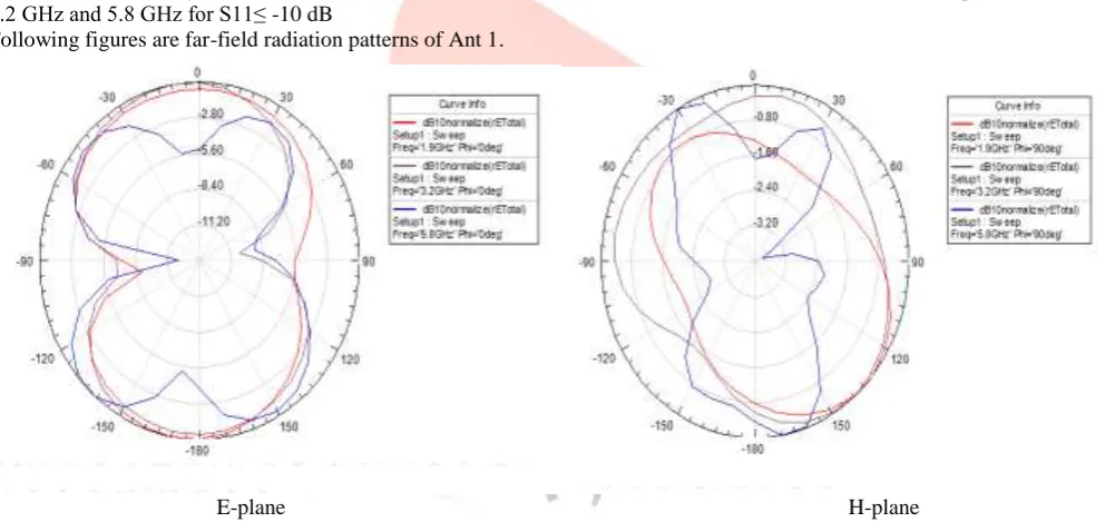
Following figures are far-field radiation patterns of Ant 1.
E-plane H-plane
Figure 9 : Simulated radiation patterns of Ant 1
Antenna 2 (tri-band antenna):
IJEDR1602006
International Journal of Engineering Development and Research (www.ijedr.org)45
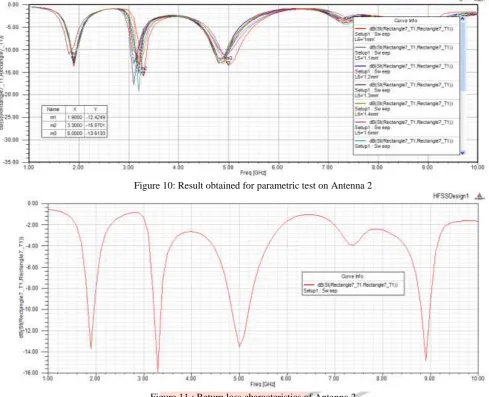
Figure 10: Result obtained for parametric test on Antenna 2Figure 11 : Return loss characteristics of Antenna 2
It can be seen from figure that the measured antenna (Ant 2) achieves three resonant modes around the frequencies of 1.9 GHz,3.3 GHz and 5 GHz for S11≤ -10 dB.
Following figures are far-field radiation patterns of Ant 2.
E-plane H-plane
© 2016 IJEDR | Volume 4, Issue 2 | ISSN: 2321-9939
IJEDR1602006
International Journal of Engineering Development and Research (www.ijedr.org)46
Figure 13 : Return loss characteristics of Antenna 3It can be seen from figure that the measured antenna (Ant 3) achieves three resonant modes around the frequencies of 1.4 GHz, 2.4 GHz ,3.4 GHz and 4.6 GHz for S11≤ -10 dB.
Following figures are far-field radiation patterns of Ant 3.
E-plane H-plane Figure 14 : Simulated radiation patterns of Ant 3.
Due to special wireless applications of the three proposed antennas maybe in portable devices, the level of cross-polarization is not substantial, so the cross-polarization patterns are not presented in the radiation patterns. It is seen that the proposed antennas exhibit nearly dipole-liked radiation patterns in the E-plane and omnidirectional radiation patterns in the H-plane at the resonant frequency bands. The radiation patterns at other frequencies within the multi-band operating band present in a similar fashion as those plotted here. It can be seen from the figures that the radiation pattern of both the proposed antenna are distorted at higher frequency, that is due to the action of the higher order mode on the patch.
VI. FUTURE WORK
The study of the number of the PROSs can be a new study direction for our future work and different multi-band operations can be obtained.
VII. CONCLUSION
The PROSs structure is introduced for multi-band microstrip antenna design.. By using the proposed structure and method (trial and error method), two triple-band and a four-band printed antenna operating at 1.5/2.6/5.6, 1.8/3.3/5.8 GHz and 1.2/2.4/3.5/4.9GHz are implemented. The obtained results demonstrate that the proposed antennas realize the design target, and the versatile PROSs structure is a suitable candidate for the multi-band antenna design in wireless communication systems.
ACKNOWLEDGMENT
IJEDR1602006
International Journal of Engineering Development and Research (www.ijedr.org)47
REFERENCES[1] Wei-Mei Li, Bo Liu, and Hong-Yi Zhao,“Parallel Rectangular Open Slots Structure in Multi-band Printed Antenna Design”, IEEE Antennas and Wireless Propagation Letters,pp.1536-1225.2015.
[2] K. Seol, J. Jung and J. Choi, “Multi-band monopole antenna with inverted U-shaped parasitic plane,” IET Electron. Lett., Vol. 42, no. 15, pp. 844-845. 2006.
[3] N. Amani, M. Kamyab, A. Jafargholi, A. Ho sseinbeig and J.S. Meiguni, “Compact tri-band metamaterial-inspired antenna based on CRLH resonant structures,” IET Electron. Lett., Vol. 50, no.12. pp. 847–848 2014.
[4] Y. T. Wan, D. Yu, F. S. Zhang and F. Zhang, “Miniature multi-band monopole antenna using spiral ring resonators for radiation pattern characteristics improvement,” IET Electron. Lett., Vol.49, no.6. pp. 382–384. 2013.
[5] H. So, A. Ando, T. Seki, M. Kawashima and T. Sugiyama , “Directional multi-band antenna employing frequency selective surfaces,” IET Electron. Lett., Vol.49, no.4.pp. 243–245. 2013.