Ion Implantation As A Route To Enhancing Osseointegration On Modified Titanium Surfaces
Thesis submitted by Lana Ahmed Shinawi
For the degree of DOCTOR OF PHILOSOPHY
In the
Faculty of Dentistry University of London
Department of Prosthetics
Eastman Dental Institute For Oral Healthcare Sciences, University College London,
256 Gray’s Inn Road, London WC1X8LD
-2003-ProQuest Number: U642773
All rights reserved
INFORMATION TO ALL USERS
The quality of this reproduction is dependent upon the quality of the copy submitted. In the unlikely event that the author did not send a complete manuscript and there are missing pages, these will be noted. Also, if material had to be removed,
a note will indicate the deletion.
uest.
ProQuest U642773
Published by ProQuest LLC(2015). Copyright of the Dissertation is held by the Author. All rights reserved.
This work is protected against unauthorized copying under Title 17, United States Code. Microform Edition © ProQuest LLC.
ProQuest LLC
789 East Eisenhower Parkway P.O. Box 1346
J4.c^ou>(ecfgment
T irst ancCforemost I wouCcCCi^ to e:)Çtenc[my (fee-pest tH an ^ to my supervisor,
(Dr. ^.J{. Jones, f o r Her continuous support an(f guidance. W itd ou t Her, tfiis word^
wouCcC never davefinisfiecf.
I also ejçtencf my gratitucfe to ^ o f essor J.J{. jC oddjrdfor tde dindness de das
sdoivn me tdrougdout my studies at tde Eastman. I tdandjDr. d.J date an d D r. D.
McDdaiCat tde ImperiaCCoCdege f o r tdeir assistance w itd tde production o f tde
samples and tde interpretation o f data.
I am forever in deSit to tde s ta ff in tde prostdetic, diomateriaCs and efectron
microscopy departments f o r tdeir deCp and advice, an d to tde frie nds wdo stood 6y and
encouraged me.
I dedicate tdis word^to myfamiCy, my mentor, my Dad, my inspiration, my
Abstract
Owing to its biocompatibility, titanium (Ti) has long been established as a dental implant material. Since its first introduction by Brânemark, numerous modifications to the original design, composition and topography have been attempted. A recent approach aims at altering the chemical composition and/or the physical properties of the very near surface of the Ti by using ion implantation. Ca ion implantation into CP Ti was reported to enhance the biological response in vitro and in vivo.
The current research explored the modification of titanium by the implantation of C a \ and Ar^ ions. A number of techniques were employed to examine the resulting surfaces. These include SEM, white light interferometry and XRD. The chemistry of the immediate surface was examined in detail using XPS, while ion distributions away from the surface were probed using SIMS.
The stability of the implanted species in the aqueous environment was investigated to explore the in vitro biological response to these surfaces by immersion in water (H2O) and a simulated physiological environment (HBSS).
The surface properties following short-term and long-term immersions were investigated at both body temperature and room temperature. Clinical implications were further assessed by investigating the effects of passivation in nitric acid (HNO3).
All surfaces displayed phosphate deposition after immersion at body temperature but Ca ion implantation was found to result in the most favourable apatite deposition from HBSS solution both at different temperatures and at short immersion times.
Contents
Acknowledgments 2
Abstract 3
Contents 5
List of Figures 11
List of Tables 17
1 Introduction 19
1.1 Titanium In Dentistry 20
1.1.1 The Biological Response 22
1.2 Design Modification of Ti Dental Implants 24
1.3 Surface Modification of Ti 27
1.3.1 Surface Texture 28
1.3.2 Surface Chemistry 30
1.4 Modification of Ti Through Ion Implantation 34
1.5 Aims And Objectives 38
1.6 The Layout of the Thesis 40
1.7 References 42
2 Techniques Applied 51
2.1 Ion Implantation 52
2.2 Physical Properties 55
2.2.1 Scanning Electron Microscopy (SEM) 55
2.2.2 White Light Interferometry (WLI) 57
2.3 Chemical Analysis 59
2.3.1 X-Ray Diffraction (XRD) 59
2.3.2 X-ray Photoelectron Spectroscopy (XPS) 63
2.3.3 Secondary Ion Mass Spectroscopy (SIMS) 71
3.1 Introduction 81
3.2 Sample Preparation 81
3.2.1 Polishing 83
3.2.2 Cleaning 84
3.2.3 Implantation 85
3.2.3.1 System Used 85
3.2.32 Choice of Ions and Implantation Dose 85
3.2.33 Cleaning 88
3.3 Immersion in Physiological Solutions 89
3.3.1 Water (H2O) 89
3.3.2 Hanks Balanced Salt Solution (HBSS) 89
3.4 Analysis 90
3.4.1 Physical Analysis 90
3.4.1.1 SEM 90
3.4.1.1.1 System Used 90
3.4.1.2 WLI 91
3.4.1.2.1 System Used 91
3.4.2 Chemical Analysis 93
3.4.2.1 XRD 93
3.4.2.1.1 System Used 93
3.4.22 XPS 94
3.4.2.2.1 System Used 94
3.4.2.22 Data Display 94
3.4.2.23 Quantification 96
3.4.23 SIMS 98
3.4.2.3.1 System Used 98
3.4.2.33 Depth Profiles 100
3.4.3 Clinical Studies 102
3.4.3.1 Passivation 102
3.5 References 104
A
Chemical And Physical Analysis of Polished And As-Implanted 1064
Ti
4.1 Introduction 106
4.2 CP
in
1074.2.1 Literature Review 107
Chemical and Physical Properties 107
The Native Oxide 107
Surface Topography 108
Surface Chemistry 109
4.2.2 Results 112
4.2.2.1 General Appearance 112
4.2.22 SEM 112
4.2.23 WLI 114
4.2.24 XRD 114
4.2.25 XPS 116
4.22.6 SIMS 127
4.2.3 Discussion 129
4.2.3.1 General Appearance 129
4.2.32 SEM 130
4.2.33 WLI 132
4.2.34 XRD 134
4.2.36 SIMS 147
4.3 Ion Implanted Ti 150
4.3.1 Literature Review 150
4.3.2 Results 153
4.3.2.1 SRIM / Profile Code 153
4.3.22 General Appearance 155
4.3.2.3 SEM 155
4.3.24 WLI 159
4.3.2.5 XRD 159
4.3.2.6 XPS 161
4.3.2.6.1 Ca Implanted Ti 161
4.3.2.62 K Implanted Ti 166
4.3.2.6.3 Ar Implanted Ti 170
4.32.7 SIMS 174
4.3.2.7.1 Ca Implanted Ti 174
4.3.2.72 K Implanted Ti 175
4.3.3 Discussion 176
4.3.3.1 SRIM and Profile Code 176
4.3.32 General Appearance 179
4.3.33 SEM 180
4.3.34 WLI 180
4.3.35 XRD 181
4.3.36 XPS 182
4.3.3.7 SIMS 192
4.33.8 Summary 197
5 Dissolution Studies 211
5.1 Literature Review 212
5.2 Results 213
5.2.1 General Appearance 214
5.2.2 SEM 215
5.2.3 XPS 220
5.2.3.1 Short Time Immersion at Room Temperature 224
5.2.3.2 Immersion At Body Temperature 228
5.2.3.3 Immersion At Room Temperature 235
5.2.4 SIMS 241
5.3 Discussion 244
5.4 References 253
6 Passivation 255
6.1 Literature Review 256
6.2 Results of Passivation 259
6.2.1 C P Ti 259
6.2.2 Ca Implanted Ti 264
6.2.3 K Implanted Ti 270
6.3 Discussion 276
6.4 References 286
7 Immersion in Simulated Body Fluid 289
7.1 Literature review 289
7.2 Results 292
7.2.1 General Appearance 292
7.2.1.1 Immersion in HBSS at Body Temperature 293
Immersion in HBSS at Body Temperature With Immediate
7.2.1.2 294
Rinsing
7.2.2.1 Immersion in HBSS at Body Temperature 296
7.2.2.2 Immersion in HBSS at Room Temperature 305
7.2.3 WLI 308
7.2.4 XPS 309
7.2.4.1 Short Time Immersion at Room Temperature 309
7.2.4.2 Immersion at Body Temperature 312
7.2.4.3 Immersion at Room Temperature 326
7.2.5 SIMS 334
7.3 Discussion 339
7.3.1 General Appearance 341
7.3.2 SEM 344
7.3.3 WLI 350
7.3.4 XPS 351
Immersion at Body Temperature 352
Immersion at Body Temperature with Delayed Rinsing 356 Immersion at Body Temperature with Immediate Rinsing 357
Sequential Immersion at Body Temperature 358
Immersion at Room Temperature 360
Sequential Immersion at Room Temperature 363
7.3.5 SIMS 364
7.4 General Discussion 365
7.5 References 368
8 Summary 373
9 Conclusions 384
10 References 385
List of Figures
1 Figure 1.1 Two Osseointegrated Ti Implants 26
1 Figure 2.1 Schematic of the Ion Implantation Process 54
1 Figure 2.2 Schematic of the Ion Implanter 55
1 Figure 2.3 Schematic of the SEM. 57
1 Figure 2.4 Schematic of the White Light Interferometer 59
1 Figure 2.5 Bragg Model of Lattice Planes. 62
1 Figure 2.6 Schematic of the Photoemission Process 65
1 Figure 2.7 Schematic Diagram of the XPS System 68
1 Figure 2.8 XPS Widescan of a CP Ti Sample. 70
Figure 2.9 Schematic Diagram of the SIMS Microprobe 74 Figure 3.1 The Two Jigs Used to Mount the Samples for Polishing. 84
1 Figure 3.2 The Wickham 200 Ion Implanter 85
1 Figure 3.3 SEM stereoscan 908 system 91
1 Figure 3.4 SEM Image of a Crater Resulting from SIMS 92
1 Figure 3.5 XRD Siemens D5000 Diffractometer 93
1 Figure 3.6 VG.ESCLAB 2201 XL 96
1 Figure 3.7 XPS Spectrum of Ti2p Region on a CP Ti Sample 98
1 Figure 3.8 SIMS Atomika 6500 99
1 Figure 4.1 Polished CP Ti Compared To Unpolished CP Ti. 112
1 Figure 4.2 SEM of Two Areas of a Polished CP Ti Disc. 113
1 Figure 4.3 XRD of CP Ti 115
1 Figure 4.4 XPS Widescan of a CP Ti Sample 116
1 Figure 4.5 XPS Widescan of a CP Ti Sample 117
Figure 4.6 XPS Widescan of a CP Ti Sample 118
1 Figure 4.7 XPS Ti2p Peak in CP Ti Samples 120
Figure 4.10 XPS O is Peak in CP Ti Samples 121
Figure 4.11 XPS G is Peak in CP Ti Samples 122
Figure 4.12 XPS C Is Peak in CP Ti Samples 123
Figure 4.13 XPS Ca2p Peak in CP Ti Samples 124
Figure 4.14 XPS Ca2p Peak in CP Ti Samples 124
Figure 4.15 XPS K2p Peak in CP Ti Samples 125
Figure 4.16 XPS K2p Peak in CP Ti Samples 125
Figure 4.17 SIMS Depth Profile of a CP Ti Sample 128 Figure 4.18 Profile Code Simulations of Ion Implantation into Ti 154 Figure 4.19 SRIM Simulations of Ion Implantation into Ti 155 Figure 4.20 SEM of Two Areas of a Ca-Ti 1 X 10^^ ions cm'^ Disc 156 Figure 4.21 SEM of Two Areas of a K-Ti 1 X 10^^ ions cm'^ Disc 157 Figure 4.22 SEM of Two Areas of an Ar-Ti 1 X 10^^ ions cm’^ Disc 158 Figure 4.23 XRD of CP Ti Compared To Ca - Ti And K - T i 160 Figure 4.24 XPS widescan of Ca-Ti at Different Implantation Doses 162
Figure 4.25. XPS Ti2p Peak in Ca-Ti Samples 163
Figure 4.26 XPS 01s Peak in Ca-Ti Samples 164
Figure 4.27 XPS C Is Peak in Ca-Ti Samples 164
Figure 4.28 XPS Ca2p Peak in Ca-Ti Samples 165
Figure 4.29 XPS Widescan of K-Ti at Different Implantation Doses 166
Figure 4.30 XPS Ti2p Peak in K-Ti Samples 167
Figure 4.31 XPS 01s Peak in K-Ti Samples 168
Figure 4.32 XPS C Is And K2p peaks in K-Ti Samples 169
Figure 4.33 XPS K2s Peak in K-Ti Samples 169
Figure 4.34 Figure 4.35
XPS Widescans of Ar-Ti at Different Implantation Doses 170
XPS Ti2p Peak in A r-Ti Samples 171
Figure 4.36 XPS 01s Peak in A r-Ti Samples 172
Figure 4.38 XPS Ar2p Peak in Ar-Ti Samples 173 Figure 4.39 SIMS Depth Profiles of Ca-Ti (1 X 10^^ ions cm‘^) 175 Figure 4.40 SIMS Depth Profile of K-Ti (1 X 10^^ ions cm'^) 176 Figure 4.41 XPS Spectra of CP Ti and Ion Implanted Ti 183 Figure 4.42 Measured 0/Ti Ratio in CP Ti And Modified Ti 187 Figure 4.43 Measured C/Ti Ratio in CP Ti And Modified Ti 190 Figure 4.44 SIMS Ionic Concentration of "^°Ca And Ions 194 Figure 4.45 Schematic illustration of the K ion depth distribution in K -
Ti.
195
Figure 5.1 Ca-Ti Samples Following 24 h Immersion in H2O. 214 Figure 5.2 SEM of CP Ti Following 24 h Immersion in H2O 216 Figure 5.3 SEM of Ca-Ti Following 24 h Immersion in H2O 217 Figure 5.4 SEM of K-Ti Following 24 h Immersion in H2O 218 Figure 5.5 SEM of Ar-Ti Following 24 h Immersion in H2O 219 Figure 5.6 XPS Ca2p Peak in Ca-Ti immersed in H2O (24 h at 37°C) 220
Figure 5.7 XPS K2s Peak in K-Ti immersed in H2O (24 h at 37°C) 221
Figure 5.8 XPS K2p Peak in K-Ti immersed in H2O (24 h at 37°C) 221
Figure 5.9 XPS Ar2p Peak in Ar-Ti immersed in H2O (24 h at 37°C) 221
Figure 5.10 XPS Ti2p Peak in CP Ti immersed in H2O (24 h at 37°C) 222
Figure 7.27 XPS Ti2p Peak in samples in HBSS at 37°C (sequential) 322 Figure 7.28 XPS P2p Peak in samples in HBSS at 37°C (sequential) 323 Figure 7.29 XPS 01s Peak in samples in HBSS at 37‘*C (sequential) 324 Figure 7.30 XPS C Is Peak in samples in HBSS at 37°C (sequential) 325 Figure 7.31 XPS Ti2p Peak in Samples in HBSS (RT + Rinsing) 327 Figure 7.32 XPS P2p Peak in Samples in HBSS (RT + Rinsing) 328 329 Figure 7.33 XPS 01s Peak in Samples in HBSS (RT + Rinsing)
Figure 7.34 XPS C Is Peak in Samples in HBSS (RT + Rinsing) 330 Figure 7.35 XPS P2p Peak in samples in HBSS at RT (sequential) 332 Figure 7.36 XPS 01s Peak in samples in HBSS at RT (sequential) 333 .334 338 Figure 7.37
Figure 7.38
XPS C Is Peak in samples in HBSS at RT (sequential) SIMS Depth Profiles of samples Immersed at 37°C
Figure 8.1 SEM of Bone-Like Cells Attachment on All Surfaces 379 Figure 8.2 Schematic Representation of The Ti Implant Components
and The Biological Interface
List of Tables
Table 2.1 Some Surface Properties Commonly Altered by Ion Implantation
52
Table 3.1 Materials And Instruments Used In Present Research 82
Table 3.2 Protocol for Polishing Ti Discs 84
Table 3.3 Implantation Doses for All Ions 87
Table 3.4 HBSS Composition 90
Table 3.5 Sputter Rate For CP Ti And Ti02 100
Table 3.6 Abundance of the Most Relevant Isotopes 101
Table 4.1 Measurement of Rq And Ra on CP Ti 114
Table 4.2 20 Values in CP Ti 115
Table 4.3 Elemental Quantification in CP Ti Samples 126 Table 4.4 Elemental Composition and Peak Positions in CP Ti 127 Table 4.5 20 Angles for hexagonal Ti, rutile and anatase Ti02 135 Table 4.6 Ti2p peak Positions in CP Ti as Reported in the Literature 137 Table 4.7 01s peak Positions in CP Ti as Reported in the Literature 140 Table 4.8 C Is peak Positions in CP Ti as Reported in the Literature 144 Table 4.9 N Is and Ca2p peak Positions in CP Ti as Reported in the
Literature
146
Table 4.10 Profile Code prediction of the Amount of Oxide Sputtered as a Result of Ion Implantation Into Ti
153
Table 4.11 Measurement of Rq And Ra on Implanted Ti 159
Table 4.12 20 Values in Ca-Ti And K-Ti 160
Table 5.1 Quantification of Samples Immersed in H2O for 24 h at 37°C 222
Table 5.2 Quantification of Samples Following Short Time Immersion at RT
227
Table 5.3 Quantification of Samples Immersed in H2O for 24 h at 37°C 234 Table 5.4 Peak Position Following 24 h Immersion in H2O at 37°C 235 Table 5.5 Quantification of Samples Immersed in H2O for 24 h at RT 240 Table 5.6 Solubility Values of Some of the Ca and K Oxides. 251 Table 6.1 Quantification of Samples passivated in HNO3 275 Table 7.1 Rq Values in Samples Following 24 h Immersion in HBSS 308 Table 7.2 Ratios on Samples Immersed at 37°C (Rinsed) 318 Table 7.3 Ratios on Samples Immersed in HBSS (Rinsed) 321 Table 7.4 Ratios on Samples sequentially Immersed at 37°C 325 Table 7.5 Ratios on Samples Immersed at RT (Rinsed) 330 Table 7.6 Ratios on samples sequentially Immersed at RT 334 Table 7.7 Commonly Reported Calcium Phosphate Phases And Their
Chemical Formula.
1 Introduction
Titanium (Ti) is an element of group 4B in the periodic table of elements. Gregor, who called it menachite, first identified it in 1791. It became known as titanium when rediscovered by Klaproth in 1795 deriving its name from the Greek mythology of the Titans. In 1887 production of only the impure form of Ti was possible and proper analysis of its properties was not possible until 1901 when Hunter was able to produce enough pure Ti to allow these to be ascertained, including low specific gravity (4.5), high melting point and resistance to corrosion. In 1938 came the breakthrough when Kroll developed a process to allow commercial scale production of Ti. The metal is present on earth as an oxide, the chief source of it being dioxide in mineral ilmenite (FeTi02) (Brown 1997).
Ti combines the strength of iron and steel with the light weight of aluminium which accounts for its widespread use in aviation, sports equipment and more relevantly medical and dental bone replacement devices (Lu et al.
strength of grade 4 CP Ti can be increased to 800 MPa by cold working (Craig 1996, Lemons 1990).
These properties make Ti an appealing material for use in medical and dental fields as will be shown in the following section. Although alloying elements are commonly added to stabilize certain phases and result in the production of numerous Ti alloys, detailed discussion of these is beyond the scope of the current work.
An attempt to provide some definitions to the most relevant and frequently used terms in the area of Ti implants is warranted to aid with the subsequent sections.
Bio-integration has been defined as the formation of a biochemical union
between the surface of an implant and the host tissue or bone (Fairpo at a/.
2001).
Bio-inertness can be described as the inability of a material to elicit any
response (be it favourable or unfavourable) upon contact with the host tissues. The use of such a material offers no merits but can inflict no harm on the host’s tissues either. A more favourable material would logically be the bio-conductive
material, which can direct tissue growth on its surface and encourage the progression of tissue growth once initiated. The more appealing and very sought after substrate in the biomedical world is a bio-inductive material, which induces relevant tissue growth by initiating nucléation on its surface.
1.1 Titanium in Dentistry
number of materials are available for such implantation, the present review is limited to CP Ti and, when relevant, Ti alloys.
Ti has been used successfully as a dental implant for the past four decades since Brânemark presented the results of his team’s research in the 1960s, which indicated the biocompatibility of Ti and the strong direct contact between living bone and the implant. Brânemark coined the term osseointeg ration, a term now synonymous with Ti as a dental and orthopaedic implant, which is taken as a measure of success and longevity of the prosthesis.
Osseointegration has been defined as “a direct functional structural connection between living bone and the surface of a load bearing implant” (Albrektsson et al. 1986). The authors suggested criteria of success that indicates the clinical performance of a successful dental implant as follows:
1. Absence of implant mobility.
2. Absence of radiolucent zones on X-rays.
3. Annual bone loss after the first year of <0.2 mm around the implant.
4. Absence of signs and symptoms such as pain, infections, neuropathies, pararsthesia and violation of the mandibular canal for individual implants.
Modification of the original Ti dental implant surface chemistry forms the basis of the current work. Prior to listing the most popular modification procedures, a resume is presented of the surface properties of CP Ti and the native oxide film. These are directly related to manufacturing processes. In addition, the biological responses and nano-scale interactions at the Ti surface following surgical implantation are considered as they are relevant to an understanding of how surface properties could subsequently alter tissue responses to an implanted material.
1.1.1 The biological response
A Ti dental implant is produced by turning or threading the pure titanium stock material, which rapidly oxidises upon exposure to air, resulting in the formation of an oxide layer in the region of 50 - 100 A thick within one minute at a rate of 1 nm in < 1 ms (Sutherland et al. 1993). The structure of this oxide depends on the manufacturing process, including pressure and speed of machining and the surface temperature. Furthermore, the cleaning and sterilization procedures that follow have a significant bearing on the surface properties of the oxide. This oxide is able to withstand physiological environments without disintegration and thus determines the interface chemistry, as the Ti metal itself does not come into contact with the biological environment (Kasemo 1983).
formation of the initial hydrated layer known as the Helmholtz layer. The ions and biomolecules present in the surrounding biofluid adhere onto this hydrated layer, thus forming the conditioning film with which the cells interact (Lausmaa
et ai. 1999). The bonding of biomolecules to the surface can occur in several
ways, including the long-range and weak van derW aals’ interactions and short- range strong chemical bonding, through ionic and covalent bond formation. These result in the thickening of the oxide layer through oxidation and hydroxylation, as well as the diffusion of mineral ions or atoms from the bioliquid and tissue into the oxide (i.e. Ca and P-containing mineral ions). Interaction with this conditioning film governs subsequent tissue response to the implant through the adsorption of larger biomolecules and proteins, which will proceed to form the bone-implant bond.
The dissolution of the protective oxide layer in the biological environment leading to corrosion appears to be a very slow process for Ti, probably due to the high stability of the oxides (Kasemo 1983, Lausmaa et ai.
It is unrealistic to ignore the important role of surface properties in the dynamics of the interaction. It has been shown that the architecture of the tissues adjacent to a Ti implant is greatly affected by the implant surface configuration (Donley et al. 1991). This includes both chemical and structural properties. Surface chemistry and energy are reported to determine the type as well as the orientation of adsorbed molecules, and consequently cellular attachment. It is established that osteoblasts and chondrocytes are sensitive to subtle differences in surface roughness and surface chemistry (Boyan at a/. 1995). Larsson established that the early phases of cortical bone formation in rabbits are determined by the surface roughness and the oxide film thickness on 99.7% CP Ti surfaces (Larsson etal. 1996).
With these surface interactions in mind, it is possible to foresee how various modifications of the Ti substrate can affect the biological response both at the early phases and in the long-term following the surgical implantation of Ti.
1.2 Design modification of Ti dentai impiants
Dental implant systems are not only classified on the basis of elemental composition (ASTM), but also on the basis of their shape and position in the host tissues following implantation. An overview of the various designs introduced and applied in the field of dentistry was published by English (English 1990) and classified the implants as:
a) Endosseous (in bone) implants which, as the name implies, are placed within the bone tissue. This group includes design concepts such as:
• The pin concept, which was originated in the 1950s by Chercheve, and was originally made of tantulum
• The platform concept, designed by Harold and Roberts in the late 1960s
• Cylindrical or root form concept as bullet, basket, screw or fin. b) Transosseous (through bone) implants, which originated in Germany in
the 1930s and were mostly applied to support a removable denture.
c) Subperiosteal (on bone) implants that were developed in Sweden by Dahl in the 1940s as complete arch castings that are placed on top of the edentulous ridge.
percentage of success with implant treatment has led to the modification of the original surgical protocol of dental implant placement.
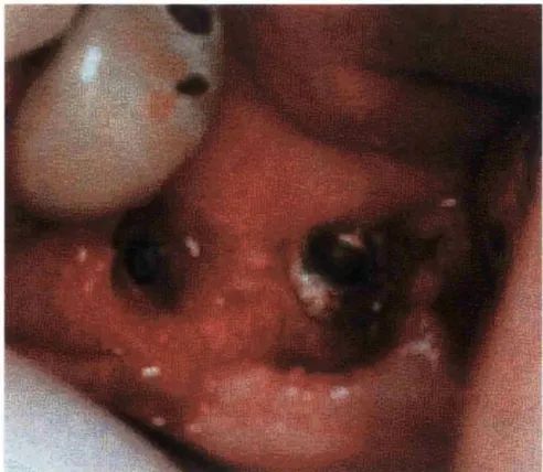
Originally, surgical implantation of Ti implants was carried out in two stages, a first stage in which the Ti implant was surgically implanted and left to heal by preventing any external loading forces for periods of 2 - 6 months to achieve healing and osseointegration. Once healing was established with satisfactory bone attachment to the implant, a second stage surgery to uncover the implant would be conducted. The implant was then left unloaded to enable healing and re-contouring of the surrounding oral mucosa and soft tissues around the implant, after which, the final stage of prosthetic rehabilitation would commence. This protocol has undergone several alterations since then, starting with the reduction of the suggested healing period between the first and second stage surgeries and leading to the practice of immediate loading in one stage surgical procedures. This cuts down the required treatment time, which initially was thought to be a major hurdle. Figure 1.1 shows a picture of two integrated implants at the second stage surgery.
Figure 1.1 Two osseointegrated TI implants as seen during the second stage surgery.
Having successfully obtained the main objectives in terms of anatomical, functional and aesthetical demands, this leaves the researchers with the challenge of preventing failure of such Ti implants, which seems to be their rare but detrimental weakness. Failure is diagnosed as the first instance at which the performance of the implant falls below a specified level. This is commonly an arbitrary rather than quantitative measure, and generally reflects in mobility of the implant, crestal bone loss greater than 0.2 mm and a number of other findings, which can be summarized as the inability to fulfil the success criteria.
Failure of implant treatment can be a result of biological inadequacy of the host tissue to establish or maintain osseointegration. Inability to establish osseointegration is referred to as early failure while late failure describes the inability to maintain osseointegration. These biological failures were reported to be rare with Ti dental implants and constitute 7.7% of the factors leading to failed implant treatment (Esposito et al. 1998a). The majority of failures of the implant treatment are attributed to mechanical factors including fractures of prosthetic and fixture components as well as iatrogenic factors. The inability to establish osseointegration forms the basis of the current work.
Modifications to the surface properties in a bid to enhance the early host response are numerous including the alteration of surface topography, roughness, oxide structure and chemical composition as shown in the next section.
1.3 Surface modification of Ti
1.3.1 Surface Texture
It as been suggested that roughened Ti surfaces elicit more favourable cellular and biological responses as a result of increasing the available surface area. This includes the introduction of surface patterns at a “large” scale of a few mm such as the popular screw threaded Ti devices and the porous or hollow implants. The later type of fixture was reported to have twice the rate of infections as solid implants. Porous implants were found to be more predisposed to early infection than dense implants, probably due to the sheltering of bacteria in these cavities away from the host defence mechanisms (Esposito et al. 1998b). Another approach to the modification of Ti texture is by increasing surface roughness to provide mechanical interlocking via pores in the range of 100 - 500 pm in dimension. Nano-scale roughness patterns have also been used (Ellingsen 1998, Ungerbock ef a/. 1994).
Larsson et a/studied the tissue response in the cortical bone of rabbits to machined 99.7% CP Ti that had undergone either electropolishing or anodic oxidation treatment, as compared to the control CP Ti surfaces which were only cleaned in alcohol. These treatments affected the properties of the oxide film including topography and thickness, but were not found to alter the composition, which mainly consisted of Ti02 covered by approximately a monolayer of hydrocarbon-dominant contamination. At 7 and 12 weeks the bone response to these surfaces displayed little difference (Larsson at al. 1994). These findings led the authors to study the early (1, 3 and 6 weeks) as well as the late (1 year) phases of bone healing around these surfaces. The smooth surfaces had less bone than the machined Ti after 6 weeks indicating a decrease in the initial rate of bone formation, which accompanied the reduction in surface roughness (Larsson at al. 1996). This was not found to affect the amount of cortical bone formation in the long term as the amount was not significantly different on all surfaces after 1 year (Larsson atal. 1997).
Although increasing surface roughness results in increased surface area, which may reduce failure by distributing loading, rough surfaces are more likely to fail as a result of recurrent marginal bone infections (Ellingsen 1998). In a clinical trial, smooth and rough Ti implants were inserted into patients and reviewed at 3, 6 and 12 months periods. The rough Ti implants were found to dramatically increase the amount of bone to implant contact in low density bone, however the authors stressed the small number of implants examined in this trial and stated that conclusions could not be drawn (Trisi at al. 1999).
acid etching and plasma spraying, it was concluded that the surface topography is not the only variable controlling the biological response, and that the surface chemistry varied according to the topographical properties (Morra et a i 2003).
1.3.2 Surface Chemistry
As Ti itself is not able to promote HA precipitation, attempts to alter its surface to promote HA nucléation have been numerous. These have largely involved pre-treatment (in solutions or through thermal oxidation) or the provision of a ceramic or glass coating rich in calcium and phosphate ions to enhance the biological response by achieving true bone bonding at the interface. Other strategies for chemical surface modification have focused on controlling the cellular response to the surface rather than HA formation. The following lists and highlights the most popular concepts of Ti modification, as the amount of work conducted in this area is beyond the limitations and the objectives of this section. A limited review of some of the clinical and/or laboratory findings is also given for the most commonly applied techniques:
a) Pre-treatment by
• Nitric acid passivation
• Calcium and phosphate containing solutions • Alkali solutions
• H2O2 treatment
72 h - 4 weeks (Ku et al. 2002). A detailed discussion of this treatment is presented in chapter 6.
Treatment of CP Ti with NaOH to form sodium hydrogels at the surface layer was reported to induce apatite deposition in simulated body fluid (SBF) environments (Kim et al. 1999). Others reported on the order of Ca and phosphate deposition on CP Ti surfaces following pre-treatment in alkali solutions (Yang et al. 1999). In a surface science report by Jones, several methods of Ti surface modification were listed, among which was the inclusion of Ca ions into Ti plates through immersion in aqueous Ca solutions. This was reported to result in the formation of calcium hydroxides and/or calcium titanate, which, upon immersion in Hanks balanced salt solution (HBSS), was found to induce apatite formation which was not detectable on untreated CP Ti plates. This report also included the results of Ti pre-treatment in solutions (containing both Ca and phosphate ions) that was found to enhance calcium phosphate precipitation in HBSS depending on the pH and ion concentration of the original solution.
Exposure to H2O2 solutions containing various metal chlorides was also found to create bioactive Ti surfaces (Jones 2001). H2O2 treatment results in oxidation and hydroxylation of the surface, as well as the production of Ti- peroxy gels, which are thought to enhance nucléation (Brunette et al. 2001). However, treatment of Ti with H2O2 containing tantalum chloride, followed by heating, provided titanium with bioactivity and enhanced interfacial in vitro bond strength between bone and the Ti implant, which was thought to be due to the thinner titania layer on the rougher Ti surface (Wu et al. 2002).
• Protein coatings
Hydroxyapatite coatings are commonly used to enhance osseointegration and short-term exposure revealed that such surfaces provide more osteophilic substrates than CP Ti resulting in more rapid bone-implant integration. The force required to detach hydroxyapatite coated Ti from bone was found to be higher than that for Ti at periods of around 12 weeks (Tengvall
et al. 1992). However, the popular hydroxyapatite coating suffers from a number
of drawbacks among which are delamination and fracture of the coating and in some cases reports of bacterial colonization. Long-term experiments have revealed problems with the adhesion of the coating and the occurrence of coating-substrate interfacial fracture (Kim at al. 1991, Li at al. 1997). Long-term perspective work over a period of 1 - 10 years found that the hydroxyapatite coated Ti was integrated in a similar manner to the CP Ti implants (Tengvall at al. 1992). The reported increase of bacterial susceptibility of HA coatings compared with Ti implants indicates the need for an alternative technique in surface modification to render the Ti itself bioactive (Ong at al. 2000).
Applying ion beam technology to modify Ti results in improved adhesion of the coating to the surface. Ca-rich coatings can be developed through several processes including ion beam mixing, ion beam deposition and plasma spraying. Ohtsuka at al (Ohtsuka at al. 1994) obtained films with improved adhesion by evaporating HA in combination with dynamic ion beam mixing using 50 keV Ca ions. Alternatively, sputtering of an HA coating with additional oxygen flow and simultaneous irradiation with 3 keV oxygen ions was reported to enhance adhesion of the coating (Ektessabi 1997).
sputtering of an hydroxyapatite matrix or alternatively, by pulsed laser deposition. This was at around the same time as the development of ion beam dynamic mixing to produce thin hydroxyapatite films by a Japanese group (Jones 2001).
Laboratory studies have shown that thin calcium phosphate coatings produced by ion beam mixing instead of plasma spraying easily dissolve in simulated body fluid (SBF) within 1 day. Treatment of these films by rapid, low temperature heating resulted in minimal dissolution and ensured the adherence of the coating to the substrate (Yoshinari et al. 1997). Hydroxyapatite coated Ti implants were found to fail at 36 months due to peri-implantitis as compared to plasma sprayed Ti which had an even earlier failure pattern associated with overloading (Ellingsen 1998).
Surface analysis of two failed plasma sprayed Ti coated dental implant systems (IMZ and ITI) showed a significant decrease in the coating thickness compared to the unused controls. This could possibly be a result of ion release into the surrounding tissue but whether such ion release initiated failure or is a common event in such implants is unknown (Esposito et al. 1998b).
Generally the hydroxyapatite coatings showed wide variation in terms of chemical composition, porosity, and crystalline and amorphous phases. Such differences are thought to influence the physical properties such as dissolution rates. Furthermore, these modified Ti implants were considered by some to be at an experimental stage in need of long-term follow up studies, as it is still unclear whether these coatings are advantageous or detrimental over the years (Ellingsen 1998).
• Reaction with antibiotics
Most of the above concepts displayed significant results in vitro but the in vivo findings are less significant and require further studies (Brunette et al.
2001).
There seems to be a general agreement that the early stages of healing are the most critical in determining the biological response, while long-term studies have shown no significant difference in the host tissues surrounding integrated Ti implants prepared by different methods. Thus it would seem logical to attempt to modify Ti surfaces to accelerate short-term bone formation on Ti through direct incorporation of Ca and/or phosphate ions. This can be achieved by a number of methods, one of which is ion implantation, which forms the basis of this investigation.
Ion implantation is a technique which enables the direct incorporation of the ions intended for implantation into the substrate. This is achieved by the acceleration of highly energised ions through an electrostatic field and onto the surface to be doped. This technique offers a number of advantages including high dopant purity and homogeneity of the dopant layer as well as control over the dose and distribution of the implanted species. It overcomes some of the common problems associated with coatings such as delamination and fracture. Ion implantation has been widely used in the semiconductor industry to alter the physical, chemical and optical surface properties of the substrate without weakening or adversely affecting the bulk material (Ziegler 1988).
1.4 Modification of Ti through ion impiantation
surgical implantation into the body. The incorporation of ions through ion implantation will without doubt alter the biological response, not only dictating the cellular and molecular interactions with the implant but also the surface physical and electrochemical properties of the substrate. Such surface composition and the resulting in vitro and in vivo response should be thoroughly addressed and investigated.
The implantation of a number of biologically beneficial and/or chemically active ions has been attempted into CP Ti. The alteration of the surface chemistry following ion implantation and different biological and clinical preparations has been studied by a number of techniques, including X-ray photoelectron spectroscopy (XPS) and secondary ion mass spectroscopy (SIMS).
Ion implantation has mainly been used in the past to enhance the physical properties of Ti. For example, ion implantation (for industrial and medical advancement) has been shown to improve hardness, coefficient of friction, wear resistance and corrosion resistance among other properties (Sioshansi 1989). In addition, it has recently been used in attempts to alter the biological response to Ti. The following section lists some of the work in this field and especially those most related to biomedical and dental applications.
compounds at the surface is known to increase resistance to wear (Hohl et al.
1995).
In a literature review, the implantation of N and C ions into Ti was similarly reported to increase wear resistance through the formation of TiN and TiC respectively at the outermost atomic surface layers. The nitrides and carbides formed were thought to prevent the movement of dislocations, thus enhancing the micro-hardness of the surface, reducing wear and improving fatigue properties (Tengvall et ai. 1992). This review also cited the results of barium ion implantation into Ti, which was reported to enhance wear and fretting resistance as well as cyclic fatigue resistance. The implantation of O^, and C* into Ti alloy at energies in the range of 5 0 - 180 keV to a dose of 1 x 10^^ ions cm‘^ was found to elevate surface hardness by more than 100% in most implanted surfaces. The friction coefficient on these surfaces was reduced by half (0.05 as compared to that of control Ti alloy at 0.1). Abrasive wear resistance was also enhanced on implanted surfaces by two orders of magnitude (Alonso etal. 1995).
Similarly, N ion implantation into Ti was found to result in a stable oxide with improved wear resistance and a decrease in oxidation rate of Ti without alteration of shape or dimensions (Arenas et al. 2000). Al ion implantation into Ti on the other hand was reported to enhance corrosion in 5 M HCL as a result of the formation of TisAI and TiAl (Tsyganov etal. 2000).
Ca ion implantation on the other hand was reported to enhance osseointegration (Hanawa et al. 1991). This group of researchers reported in
vitro and in vivo enhancement of calcium phosphate deposition on Ca implanted
cultured on the Ca implanted Ti, as well as increased early bone formation around Ca ion implanted Ti inserted into rat tibia (Hanawa et al. 1993, Hanawa
at al. 1995, Hanawa at al. 1996a, Hanawa at al. 1996b, Hanawa at al. 1998b,
Hanawa atal. 1998a).
Reports of ion implantation into Ti with the aim of modifying the biological response and enhancing in vitro nucléation include the work of Wieser at al,
where Ca and P ion implantation into CP Ti was reported to result in the formation of CaO. This indicated clearly the formation of a new crystalline phase in the case of Ca ion implantation, as opposed to the amorphous surface resulting from P ion implantation (Wieser at al. 1999). Similarly, the double implantation of Ca and P ions into Ti at a Ca/P ratio of 1.7 was found to enhance mineralization in simulated body fluid (SBF) by inducing heterogeneous nucléation and growth of hydroxyapatite relative to the control CP Ti. This enhancement was related to the presence of surface Ca^^ and HP04^' (Pham at al. 2000).
In a study of bacterial colonization and adhesion of Porphyromonas
gingivalis (P.g) and Actinobacillus actinomycetemcomitans (A.a), Ca'", N"* and
ions were implanted into Ti surfaces. The Ca implanted surfaces displayed an increase in both P.g and A.a as compared to the F implanted Ti surfaces in which a decrease in bacterial adhesion was noted for both P.g and A.a
(Yoshinari et al. 2000).
Amino group implantation into Ti with NH2'" groups was reported to result in the formation of TiN, accompanied by thickening of the oxide in excess of 61 nm as indicated by secondary ion mass spectroscopy (SIMS) analysis. Preliminary biological work revealed more favourable attachment and spread of MC3T3-E1 osteoblasts on the implanted Ti surfaces as opposed to hydroxyapatite surfaces (Yang et al. 2001).
More recently, the implantation of C", CO"", and inert Me"" into CP Ti and Ti alloy was reported to improve integration (as % bone-implant contact) especially on C and CO implanted surfaces (Maeztu et al. 2003).
1.5 Aims and Objectives
Previously, Ca ion implantation into Ti surfaces was claimed to enhance the biological response when compared to CP Ti (Hanawa et al. 1993, Hanawa
et al. 1995, Hanawa 1999). However, these claims were challenged due to the
the depth distribution of the implanted species without acknowledging the differing sputter rate of heavier particles as compared to the lighter ones.
However, similar reports on ion implantation into Ti fail to acknowledge the affect of the ion implantation process itself on modifying the surface physical properties. These include the direct physical effects of the ion bombardment process which results in the sputtering of the oxide layer, creation of vacancies and defects at the surface among other lattice modifications. Such modification could have a bearing on the biological response, since it has been shown that the implantation of inert Ne^ gas into Ti surfaces resulted in altering and even improving the bone integration in vitro (Maeztu et ai. 2003).
Therefore, investigation of whether the implantation of any ion can cause similar results was among the aims of the present work. Ca^, and Ar^ ions were chosen for implantation into CP Ti as they have comparable masses and should implant in an identical manner inflicting similar surface damage while resulting in a diverse chemical surface modification. Ar"" was used as a control for the implantation process due to its chemically inert nature.
examination of the surfaces and measurement of the surface roughness at baseline and (when applicable) following immersion.
The current work has been carried out in parallel with biological studies conducted by the tissue-engineering group at the Eastman Dental Institute for Oral Healthcare Sciences. The biological work demonstrated significantly lower attachment of bone-like MG 63 cells on Ca ion implanted Ti as compared to CP Ti. However, SEM indicated a greater degree of cell spreading on these surfaces than on CP Ti at 4 h seeding. Meanwhile, K and Ar ion implanted Ti showed similar cellular attachment as to the control Ti but a lesser degree of cell spreading as compared to the Ca implanted surfaces. This was especially the case on the Ar implanted Ti, which displayed rounded features indicating that a proportion of the attached cells did not spread on this particular surface. The results of the biological studies will be further detailed in chapter 8 in conjunction with the findings of the current work.
1.6 The layout of the thesis
1.7 References
Adell, R, Lekholm, U, Rockier, B, and Branemerk P.I. 1981, "A 15-Year Study of Osseointegrated Implants in the Treatment of the Edentulous Jaw", International Journal of Oral Surgery. Vol. 10, pp. 387-416.
Albrektsson, T, Branemerk P.I, Hansson, H, Kasemo, B, Larsson, K, Lundstrom, L, Mcqueen, D. H, and Skalak, R. 1983, "Interface Zone of Inorganic Implants In Vivo: Titanium Implants in Bone", Annals Of Biomedical Engineering, Vol. 11, no. 1, pp. 1-27.
Albrektsson, T, Dahl, E, Enbom, L, Engevall, S, Engquist, B, Eriksson, R. A, and Feldmann, G. 1987, "Osseointegrated Oral Implants. A Swedish Multicenter Study of 8139 Consecutively Inserted Nobelpharma Implants", Journal of Periodontology, Vol. 59, no. 5, pp. 287-294.
Albrektsson, T, Zarb, G, Worthington, P, and Eriksson, R. A. 1986, "The Long- Term Efficacy of Currently Used Dental Implants: A Review and Proposed Criteria of Success", International Journal of Oral and Maxillofacial Implants, Vol. 1, pp. 11-25.
Alonso, F, Arizaga, A, Quainton, S, Ugarte, J. J, Viviente, J. L, and Ohate, J. I. 1995, "Mechanical Properties and Structure of Ti6AI4V Alloy Implanted With Different Light Ions", Surface and Coatings Technology, Vol. 74 -75, pp. 986- 992.
Boyan, B. D, Hummert, T. W, Kieswetter, K, Schraub, D, Dean, D, and Schwartz, Z. 1995, "Effect of Titanium Surface Characteristics on Chondrocytes and Osteoblasts In Vitro", Cells And Materials, Vol. 5, no. 4, pp. 323-334.
Brown, D. 1997, "All You Wanted To Know About Ti, But Were Afraid To Ask", British Dental Journal, Vol. 182, No. 10 May 24, pp. 393-394.
Brunette, D. M, Tengvall, P, Textor, M. and Thomsen, P. 2001, “Titanium in Medicine”. Springer.
Craig, R. G. 1996, Restorative Dental Materials, Tenth Edition, Mosby.
Donley, T. G. and Gillette, W. B. 1991, "Titanium Endoosseous Implant - Soft Tissue Interface: A Literature Review", Journal of Periodontology, Vol. 62, pp.
153-160.
Ektessabi, A. M. 1997, "Surface Modification of Biomedical Implants Using lon- Beam-Assisted Sputter Deposition", Nuclear Instruments and Methods B, Vol. 127, pp. 1008-1018.
Ellingsen, J. E. 1998, "Surface Configurations of Dental Implants", Periodontology 2000, Vol. 17, pp. 36-46.
English, C. 1990, "An Overview of Implant Hardware", JADA, Vol. 121, p. 360. Esposito, M, Lekholm, U, Hirsch, J. M. and Thomsen, P. 1998a, "Biological Factors Contributing To Failures of Osseointegrated Oral Implants (I). Success Criteria and Epidemiology, European Journal of Oral Sciences, Vol. 106, pp 527-551.
Esposito, M, Hirsch, J. M, Lekholm, U, and Thomsen, P. 1998b, "Biological Factors Contributing To Failures of Osseointegrated Oral Implants (II). Etiopathogenesis", European Journal of Oral Sciences. 106, pp. 721-764.
Hanawa, T. and Ota, M. 1991, "Calcium Phosphate Naturally Formed on Titanium in Electrolyte Solution", Biomaterials, Vol. 12, no. October, pp. 767- 774.
Hanawa, T, Ukai, H, and Murakami, K. 1993, "X- Ray Photoelectron Spectroscopy of Calcium - Ion - Implanted Titanium", Journal of Electron Spectroscopy and Related Phenomena, Vol. 63, pp. 347-354.
Hanawa, T, Ukai, H, Murakami, K, and Asami, K. 1995, "Structure Of Surface - Modified Layers of Calcium-lon-lmplanted Ti6AI4V And Ti56Ni", Materials Transactions, JIM, Vol. 36, no. 3, pp. 438-444.
Hanawa, T, Asami, K, and Asaoka, K. 1996a, "AES Studies on the Dissolution of Surface Oxide from Calcium-lon-lmplanted Titanium in Nitric Acid and Buffer Solutions", Corrosion Science, Vol. 38, no. 11, pp. 2061-2067.
Hanawa, T, Asami, K, and Asaoka, K. 1996b, "Microdissolution of Calcium Ions from Calcium-lon-lmplanted Titanium", Corrosion Science, Vol. 38, no. 9, pp.
1579-1594.
Hanawa, T, Asami, K, and Asaoka, K. 1998a, "Repassivation of Titanium and Surface Oxide Film Regenerated In Simulated Bioliquid", Journal of Biomedical Material Research, Vol. 40, pp. 530-538.
Hanawa, T, Kon, M, Doi, H, Ukai, H, Murakami, K, Hamanaka, H, and Asaoka, K. 1998b, "Amount of Hydroxyl Radical on Calcium-lon-lmplanted Titanium and Point of Zero Charge of Constituent Oxide of the Surface-Modified Layer", Journal of Materials Science: Materials in Medicine, Vol. 9, pp. 89-92.
Haraldson, T. and Zarb, G. 1988, "A 10-Year Follow up Study of The Masticatory System After Treatment With Osseointegrated Implant Bridges", Scandinavian Journal of Dental Research, Vol. 96, pp. 243-252.
Heide, N, Siemenemeyer, B, and Schultze, J. W. “Surface Characterization and Electrochemical Behaviour of Nitrogen Implanted And Carbon Implanted Titanium”, Surface International Analysis, Vol. 19, no. 1-12, pp. 423-429. 1992. Henry, P. J, Tolman, D. E, and Bolender, C. 1993, "The Application of Osseointegrated Implants In the Treatment of Partially Edentulous Patients: Three-Year Results of A Prospective Multicenter Study", Quintessence International Vol. 24, pp. 123-129.
Hohl, F, Berndt, H, Mayr, P, and Stock, H. R. 1995, "Implantation of N^'', O'" And CO^ Ions into Titanium and Ti6AI4V", Surface and Coatings Technology, Vol. 74 - 75, no. pp. 765-769.
Howlett, C. R. 1999, "Early Bone Formation around Calcium-lon-lmplanted Titanium Inserted Into Rat Tibia", Journal of Biomedical Material Research, Vol. 44, pp. 352-353.
Jones, F. H. 2001, "Teeth and Bones: Applications of Surface Science to Dental Materials and Related Biomaterials", Surface Science Reports, Vol. 42, no. 3 - 5, pp. 75-206.
Kasemo, B. 1983, "Biocompatibility of Titanium Implants: Surface Science Aspects", Journal of Prosthetic Dentistry, Vol. 49, no. 6, pp. 832-837.
Kim, C. S. and Ducheyne, P. 1991, "Compositional Variations in the Surface and Interface of Calcium Phosphate Ceramic Coatings on Ti and Ti6AI4V Due to Sintering and Immersion", Biomaterials, Vol. 12, pp. 461-469.
Treatment", Journal of Biomedical Material Research, Vol. 45, no. 2, pp. 100- 107.
Krupa, D, Baszkiewicz, J, Kozubowski, J. A, Barcz, A, Sobczak, J. W, Bilinski, A, Lewandowska-Szumiel, M, and Rajchel, B. 2001, "Effect of Calcium-lon Implantation on the Corrosion Resistance and Biocompatibility of Titanium", Biomaterials, Vol. 22, pp. 2139-2151.
Krupa, D, Baszkiewicz, J, Kozubowski, J. A, Barcz, A, Sobczak, J. W, Bilinski, A, Lewandowska-Szumiel, M, and Rajchel, B. 2002, "Effect of Phosphorous-lon Implantation on the Corrosion Resistance and Biocompatibility of Titanium", Biomaterials, Vol. 23, pp. 3329-3340.
Ku, C. H, Pioletti, D. P, Browne, M, and Gregson, P. J. 2002, "Effect of Different Ti6AI4V Surface Treatments on Osteoblast Behaviour", Biomaterials, Vol. 23, pp. 1447-1454.
Laney, W. R, Jemt, T, Harris, D, Henry, P. J, Krogh, P. H. J, Polizzi, G, and Zarb, G. 1994, "Osseointegrated Implants For Single-Tooth Replacement: Regress Report From A Multicenter Prospective Study After 3 Years", International Journal of Oral And Maxillofacial Implants, Vol. 9, no. 1, pp. 49-54. Larsson, C, Thomsen, P, Lausmaa, J, Rodahl, M, Kasemo, B, and Ericson, L. E. 1994, "Bone Response to Surface Modified Titanium Implants: Studies on Electropolished Implants with Different Oxide Thicknesses and Morphology", Biomaterials, Vol. 15, no. 13, pp. 1062-1074.
Larsson, C, Thomsen, P, Aronsson, B.-O, Rodahl, M, Lausmaa, J, Kasemo, B, and Ericson, L. E. 1997, "Bone Response To Surface Modified Titanium Implants; Studies on The Tissue Response After 1 Year To Machined And Electropolished Implants With Different Oxide Thicknesses", Journal of Material Science - Materials in Medicine, Vol. 8, no. 12, pp. 721-729.
Lausmaa, J, Kasemo, B, and Mattsson, H. 1990, "Surface Spectroscopic Characterization of Titanium Implant Materials", Applied Surface Science, Vol. 44, pp. 133-146.
Lausmaa, J, Lofgren, P, and Kasemo, B. 1999, "Adsorption and Coadsorption of Water and Glycine on TiOz", Journal of Biomedical Material Research, Vol. 44, pp. 227-242.
Lemons, J. E. 1990, "Dental Implant Biomaterials", JADA, Vol. 121, No. December, pp. 716-719.
Li, X, Weng, J, Tong, W, Zuo, C, Zhang, X, Wang, P, and Liu, Z. 1997, "Characterization of Hydroxyapatite Film With Mixed Interface By Ar^ Ion Beam Enhanced Deposition", Biomaterials, Vol. 18, pp. 1487-1493.
Lu, G, Bernasek, S. I, and Schwartz, J. 2000, "Oxidation of A Polycrystalline Titanium Surface by Oxygen and Water", Surface Science, Vol. 458, pp. 80-90. Maeztu, M. A, Alava, J. I, and Escoda, C. G. 2003, "Ion Implantation: Surface Treatment for Improving The Bone Integration of Titanium and Ti6AI4V Dental Implants", Clinical Oral Implant Research, Vol. 14, no. 1, pp. 57-62.
Ohtsuka, Y, Matsuura, M, Chida, N, Yoshinari, M, Sumii, T, and Dérand, T. 1994, “Formation of Hydroxyapatite Coating on Pure Titanium Substrates by Ion Beam Dynamic Mixing", Surface and Coatings Technology, Vol. 65, pp. 224- 230.
Ong, J. L. and Chan, D. 2000, "Hydroxyapatite and Their Use as Coatings in Dental Implants: A Review", Critical Reviews in Biomedical Engineering, Vol. 28, no. 5 - 6 , pp. 667A-707A.
Pham, M. T, Matz, W, Reuther, H, Richter, E, Steiner, G, and Oswald, S. 2000, "Ion Beam Sensitizing of Titanium Surfaces To Hydroxyapatite Formation", Surface and Coatings Technology, Vol. 128-129, pp. 313-319.
Schwartz, Z, Martin, J. Y, Dean, D, Simpson, J, Cochran, D. L, and Boyan, B. D. “Effect of Titanium Surface Roughness on Chondrocyte Proliferation, Matrix Production and Differentiation Depends on the State Of Cell Maturation”, 1996. Journal of Biomedical Material Research, Vol. 30, no. 2, pp. 145-155.
Shapiro, P. A. and Kokich, V. G. 1988, "Uses of Implants in Orthodontics", Dental Clinics of North America, Vol. 32, no. 3, pp. 539-550.
Sioshansi, P. 1989, "Surface Modification of Industrial Components by Ion Implantation", Nuclear Instruments and Methods B, Vol. 37 - 38, Pp. 667-671. Stanford, C. M, Keller, J. C, and Solursh, M. 1994, "Bone Cell Expression on Titanium Surfaces Is Altered By Sterilization Treatments", Journal of Dental Research, Vol. 73, no. 5, pp. 1061-1071.
Sutherland, D. S, Forshaw, P. D, Allen, G. C, Brown, I. T, and Williams, K. R. 1993, "Surface Analysis of Titanium Implants", Biomaterials, Vol. 14, no. 12, pp. 893-899.
Trisi, P, Rao, W, and Rebaudi, A. 1999, "A Histometric Comparison Of Smooth And Rough Titanium Implants in Human Low-Density Jawbone", International Journal of Oral And Maxillofacial Implants, Vol. 14, pp. 689-698.
Tsyganov, I, Wieser, E, Matz, W, Mücklich, A, Reuther, H, Pham, M. T, and Richter, E. 2000, "Phase Formation in Aluminium Implanted Titanium and the Correlated Modification of Mechanical and Corrosive Properties", Thin Solid Films, Vol. 00, pp. 188-197.
Ungerbock, A. and Rahn, B. 1994, "Methods to Characterize the Surface Roughness of Metallic Implants", Journal of Materials Science: Materials In Medicine, Vol. 5, pp. 434-440.
Van Steenberghe, D. 1989, "A Retrospective Multicenter Evaluation of the Survival Rate of Osseointegrated Fixtures Supporting Fixed Partial Prostheses In The Treatment of Partial Edontulism", Journal Of Prosthetic Dentistry, Vol. 61, pp. 217-223.
Wieser, E, Tsyganov, I, Matz, W, Reuther, H, Oswald, S, Pham, M. T, and Richter, E. 1999, "Modification of Titanium by Ion Implantation of Calcium And / Or Phosphorus", Surface and Coatings Technology, Vol. I l l , Pp. 103-109. Wisbey, A, Gregson, P. J, Peter, L. M, and Tuke, M. 1991, "Effect of Surface Treatment on the Dissolution Of Titanium - Based Implant Materials", Biomaterials, Vol. 12, pp. 470-201.
Wu, J. M, Hayakawa, S, Tsuru, K, Osaka, A, and Wang, X. X. 7n Vitro
Evaluation on Bone-Bonding of Chemically Modified Titanium”, 2002, Bioceramics 14. Key Engineering Materials, Vol. 218, no. 2, pp. 141-144.
Aqueous Solution", Journal of Biomedical Material Research, Vol. 47, no. 2, pp. 213-219.
Yang, Y. Z, Tian, J. M, Tian, J. T, and Chen, Z. Q. 2001, "Surface Modification of Titanium Through Amino Group Implantation", Journal of Biomedical Material Research, Vol. 55, pp. 442-444.
Yoshinari, M, Oda, Y, Kato, T, Okuda, K, and Hirayama, A. 2000, "Influence of Surface Modification to Titanium on Oral Bacterial Adhesion In Vitro", Journal of Biomedical Material Research, Vol. 52, pp. 388-394.
Yoshinari, M, Watanabe, Y, Ohtsuka, Y, and Derand, T. 1997, "Solubility Control of Thin Calcium-Phosphate Coatings with Rapid Heating", Journal of Dental Research, Vol. 76, no. 8, pp. 1485-1494.
2 Techniques applied
2.1 Ion Implantation
Ion implantation is a process whereby ionised atoms or molecules are accelerated through an electrostatic field into the substrate to be implanted. The theory of ion implantation was proposed in 1913 by Niles Bohr, however the technique was developed much later and the first patent for ion implantation was obtained in 1957 by Shockley, who described the lattice damage brought about by the implantation process and suggested post-annealing to repair it (Ziegler 1988). Ion implantation nowadays is widely applied in industry for the production of semiconductor circuits (Ryssel e tal. 1986, Ziegler 1988).
Ion implantation allows the alteration of the chemical, physical and optical properties of a solid and is commonly used to alter the composition, structure or morphology of the near surface layers. Ion implantation has been shown to enhance wear resistance, corrosion resistance, hardness and coefficient of friction in industrial applications without adversely affecting the bulk properties of the solid (Sioshansi 1989). Table 2.1 lists some of the surface properties that may be altered by ion implantation (Townsend et ai. 1994).
Mechanical Chemical Electrical Optical
Microhardness Corrosion Resistivity Colour
Friction Passivation Photoconductivity Reflectivity
Adhesion Diffusion Electron mobility Transmission
Wear Reactivity Semiconductivity Opteolectronics
Table 2.1 Som e surface properties which can be aitered b y ion im piantation.
depth control, which is applicable to most ions and achievable at low or even ambient temperatures (Townsend et al. 1994). In addition to speed, it is possible to control dopant mass as well as homogeneity and reproducibility of the surface modified layer, which is not prone to the fracture or delamination that is often associated with surface coatings. Ion implantation does not impair the mechanical bulk properties of the substrate. It also allows for multiple implantations of variant species into the substrate (Li etal. 1997).
However, possible damage to the substrate crystal lattice can arise as a result of the collision of the dopant ions with the surface. The technique is also limited to the surface region and is unsuitable for bulk doping. The depth profile can also be altered from that intended due to diffusion, ion channelling or sputtering (Townsend et al. 1994). However these can all be modelled using computer simulation programmes (Chapter 3).
Primary Ion Beam Sputtered Particles
2 2^ 2 2 surface
O 0 C > 0 \p 0 0
2 2 2 2 Depth of Implantation
o o o o o o o
of Collision CascadeFigure 2.1 Schem atic o f the ion im piantation process
The depth of the implantation varies from a few nanometres to several micrometers depending on the energy of implantation and the mass of the incident ion as well as that of the substrate atoms (Ziegler 1988).
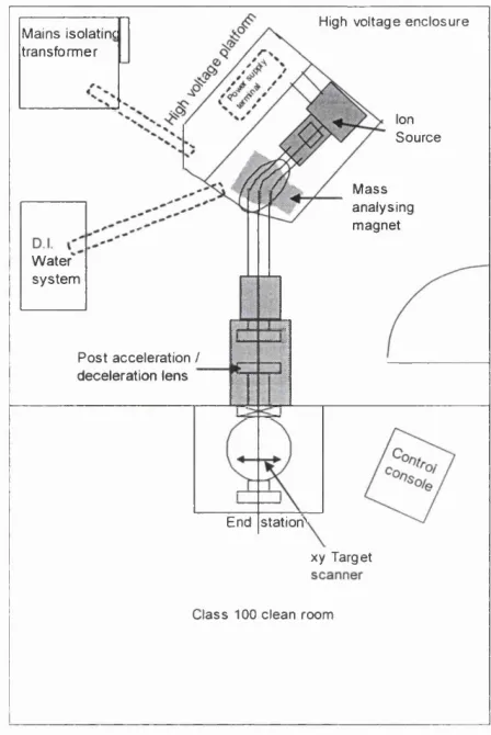
High voltage enclosure M ains isolatinc
transform er
Ion Source
M ass analysing magnet W a te r
system
Post acceleration / deceleration lens
End statiotf xy Target
Class 100 clean room
Figure 2.2 Schematic o f the Ion Implanter (adapted from user’s manual).
2.2 Physical properties
2.2.1 Scanning Electron Microscopy
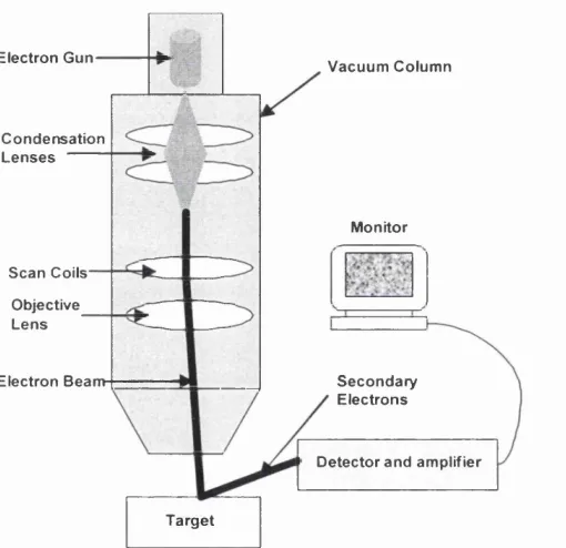
A voltage is applied across the tungsten filament in the electron gun to generate an electron beam at energies between 2 keV and 40 keV. The beam is accelerated down the beam column to the sample surface. As the beam passes through the beam column it is condensed by a condenser lens to demagnify the electron beam and limit the current in the beam, which is then passed through a scan generator causing it to move and scan across the specimen after being focused by the objective lens. As the electron beam hits the sample surface it results in various interactions with the material in what is known as the interaction volume. Although radiation is generated in this volume, it is not easily absorbed as it escapes undetected from the sample. Meanwhile the ejected secondary electrons from the near surface region can either be back-scattered electrons with a broad energy span or outer shell atomic electrons of low energy. These are collected by a backscatter detector or a secondary electron detector respectively and are then converted to voltage and amplified. The backscattered mode is used for investigating compositional variation in the sample as it depends on the atomic number of the sample, while the unscattered electrons are used to provide high-resolution imaging. The amplified voltage of the unscattered electrons alters the intensity of the spot of light on the cathode-ray tube (CRT) producing an image that consists of thousands of spots of varying intensity on the face of the CRT, which correspond to the sample surface (Lorretto 1993, Reimer 1998, Good hew et al.