Division IX (include assigned division number from I to X)
SEISMIC ANALYSIS OF BASE-ISOLATED NUCLEAR POWR PLANT
CONSIDERING SOIL-STRUCTURE INTERACTION
Choon-Gyo Seo1, Sang-Hoon Lee2, Hyun-Sung Park3 and Chul-Soon Choi4
1
Senior Engineer, KEPCO E&C, Korea ([email protected])
2
Specialist, KEPCO E&C, Korea ([email protected])
3
Junior Engineer, KEPCO E&C, Korea ([email protected])
4
Excutive Director, KEPCO-E&C, Korea ([email protected])
ABSTRACT
This paper proposes an efficient method to obtain the non-linear seismic response of a base isolated nuclear power plant(NPP) considering the soil-structure interaction(SSI). Hybrid methods combining frequency and time domain techniques are often considered as useful tools to solve SSI systems with structural non-linear behavior. However, most former hybrid methods need the iterative techniques to match SSI systems at time domain and frequency domain. A slightly new methodology, direct-hybrid-frequency-time-domain method, is proposed to get more realistic dynamic response at non-linear SSI problem. The proposed method is rigorous technical background without iteration scheme for convergence of restoring force. Under the assumption structural non-linear behavior is only occurred at the base bearings of base isolated NPP, this method is applied to solve the non-linear seismic response of the base isolated NPP structure with the next three main steps. First step is the calculation and extraction of transfer functions which are the frequency-dependent displacements on attached nodes for a whole SSI system corresponding to the unit motion. Second step includes the separating super-structure system from SSI system and computing the real time force of the interface nodes defined at contact surface between super-structure basemat and soil region. Non-linear equation of motion using well-known conventional time domain analysis technique is applied as a final step. To show the validation of the proposed methodology, the dynamic analyses for a typical NPP isolated by the lead-rubber bearing is executed. The calculated responses are demonstrated by way of comparison with the results obtained by the proposed methodology on the linear and non-linear states.
Key word: nonlinear soil-structure interaction, nuclear power plant, base isolation
INTRODUCTION
and guidelines in many countries, allows modeling of the inelastic behavior of structural systems. The frequency dependency of soil-structure impedance characteristics is usually considered in a numerical method performed in the frequency domain, whereas the nonlinearity of super structures is normally reflected in the time domain because the inelastic bilinear behavior of materials and structural members strongly depends on the stress or force-displacement path being integrated stepwise. Even the technical background is not seemed strong, a variety of methods considering the frequency-dependent impedance functions in time-history analysis have been proposed. Those procedures having the terminologies of multi-step or hybrid frequency time domain restrain the full use of frequency-dependent impedance capacity to consider inelastic behavior in the super-structure [1, 2, 3]. The equations of motion assumed to linear or equivalent linear system for a certain reference model is usually solved in frequency domain and nonlinear effects in the time domain are evaluated and treated as pseudo-forces. Depending on the degree of nonlinearity of the SSI system, the procedures may require large iteration works sometimes causing divergence. Another method of hybrid-time-frequency domain approach was also developed in 1998 [4]. Soil is represented using frequency-independent springs, dashpots, and possibly masses, and the equation of motion defined in the time domain is solved considering nonlinearity in SSI system. The feature of this method is available to analyze the non-linear SSI system with a rapid convergence
This study describes the new procedure that is more efficient and accurate approach (direct-hybrid-frequency-time-domain method; DHFTD method) for a nonlinear SSI problem. Proposed procedures directly provide nonlinear seismic responses of the reduced super-structure system without iteration scheme to be used for finding restoring force. The procedures are set up three steps; Transfer functions which are the frequency-dependent displacements on attached nodes for a whole SSI system corresponding to the unit motion are calculated at first step. Second step includes separating super-structure system from SSI system and computing the real time force of the interface nodes defined at the contact surface between super-structure basemat and soil. And the nonlinear equation of motion using a well-known conventional time domain analysis method is solved to get seismic responses.
A numerical example is presented for the seismic linear or nonlinear responses of a typical NPP structure with base isolation to show the effectiveness of the multi-step hybrid domain analysis procedure. All procedures to be shown more specifically at next section are implemented through KIESSI program composed by three-dimensional coupled finite and dynamic infinite elements [5,6,7] and numerical analysis results on the example are also from KIESSI.
THEORETICAL BACKGROUND
The first step is the linear analysis of the whole SSI system shown in Figure 1. The descretized algebraic equation of motion for seismic forced SSI system is arranged for the indexes of four kind of degree of freedom in frequency domain and could be set below.
* *
*
*
( )
( )
0
0
( )
0
0
( )
( )
( )
0
( )
0
( )
0
( )
( )
( )
( )
( )
0
0
( )
( )
( )
ss sa s
as aa ab a
b
ba bb be
eq e
eb ee ee
w
w
w
w
w
w
w
w
w
w
w
w
w
w
w
w
é
ù ì
ü ì
ü
ê
ú ï
ï ï
ï
ê
ú ï
ï ï
=
ï
í
ý í
ý
ê
ú
ï
ï ï
ï
ê
ú
ï
ï ï
ï
ê
+
ú
î
þ
î
þ
ë
û
S
S
U
S
S
S
U
U
S
S
S
F
U
S
S
S
(1)
( )
(
)
21 i2 d
w = + b -w
S K M,
( )
(
)
( )
2( )
1 i2 d
w = + b w w- w
S K M (2)
DOF along the interface(Ga)between structure and near field soil; e also denotes the DOF along the
interface(Ge)between near field soil and far field soil region; S( )
w
andS
( )
w
are the dynamic stiffnessmatrixes of finite and infinite elements respectively with a elementary material hysteretic damping(bd) effect; K
( )
w and M( )
w are the frequency dependent stiffness and mass matrices of infinite elements.; other entries of the matrix are can be presented as* ( ) ( ) ( )
aa w = aa w + bb w
S S S , *
( ) ( ) T ( ; ) ss w = ss w + is ii keff w is
S S T S T , (3)
*
( ) ( ) ( )
bb w = bb w + ee w
S S S , U*s( )w = Us( ),w Ui( )w T
where, subscript i stands for the DOF related with the base isolation; Tis is the transform matrix defining the location of the base isolation; keff is the equivalent linear stiffness constant of isolation bearing
shown in Figure 4. In this analysis, one can obtain the frequency response functions (Ua( )w , transfer function) on the interface Ga corresponding to unit motion.
Second step is a restructuring work to reduce the interested structural model separated from the whole SSI model and computing the real time signal force on the attached interface nodes for an input control motion. This procedure is almost same to that of analysis for a multiply-supported multi-degree-of-freedom secondary structure system shown in Figure 2. Linear equation of motion for a separated secondary system can be obtained as below[8].
( ) ( ) ( ) ( ) ss s t + ss s t + ss s t = - a t
M u C u K u f (4)
where, us( ),t us( ),t us( )t are the unknown absolute acceleration, velocity and displacement of
secondary system; Msa,Csa,Ksa are the coupled mass, damping and stiffness matrixes; fa( )t is the interaction force on DOF a . The interaction force fa( )t is usually calculated in time domain as
( ) ( ) ( ) ( )
a t = sa a t + sa a t + sa a t
f M u C u K u . In this study, however, calling the prescribed transfer function Ua( )w
stored at first step, the interaction force takes the following transformed terms as
{
}
(
{
}
)
(
)
1 ' 2 1 ( ) ( ) ( ) ( ) ( ) 2( ) 1 2
i t
a a na a g
na d na na
t X e d
i
w
w w w w w
p
w b w
¥ --¥ = Á = = +
-ò
f F S U
S K M
(5)
where, Sna( )w is the frequency-dependent dynamic stiffness for coupled matrix terms; Xg( )w is
Fourier spectrum of the control motion x tg( ). The interaction force consequently is the external
load vector for linear SSI system and the equivalent effective stiffness in the equation (2). Final step is the non-linear dynamic analysis of the SSI system with base isolation in time domain, and then the equation (4) may be precisely changed as
{
}
1
' ' ' ' ' '
' ' i
' ' ' ( )
( ) ( ) ( ) 0
( ) ( ) ( ) 0
( ) ( ) ( )
ss s ss s s
ii i ii i
a a a a a a a
si si
is sa is sa
a s a s a
t t t
t t t
t t t - w
+ + = -Á ì ü é ùì ü é ùì ü ì ü ï ï ï ï ï ï ï ï ê úí ý ê úí ý í ý í ý ê úï ï ê úï ï ï ï ï ï ê úî þ ê úî þ ë û ë û î þ î þ
m m 0 u c 0 u f
m m m u u f
0 m m u 0 u f F
c
c c c
c c
where, a' denotes the DOF of nodes not fixed with on attached finite elements; fi( )t is the vector of restoring forces in the base isolation which may be especially non-linear. The technique for solving the equation (6) is well known as an implicit methodology using the Newmark method with Newton-Raphson iteration technique[10].
The above multi-stepping analyzing work can be sequentially carried out using KIESSI program. The program has been well established by various researchers, and it can analyze the complex problem of 2D, AXI and 3D multi-physical interactive systems such as SSI, structure interaction and fluid-structure-soil interaction, primary-secondary structural interaction etc.
NUMERICAL EXAMPLE AND DESCRIPTION
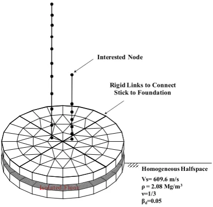
Superstructure; The schematic view of superstructure as a stick model shown in Figure 3 is selected for numerical example which shows that the upper containment structure is modeled by the beam sticks with lumped nodal masses, while the floor slab perimeter is rigidly linked on the base concrete footing. The total weight of the super-structure is 29,000 tonf. All other structural properties are quoted from the SASSI manual [9]. The lowest three natural frequencies under the fixed base condition were confirmed to 5.26, 11.9 and 15.6 Hz, respectively
Soil; Considered soil is assumed to uniform half-space foundation, and the basemat of the example structure is located at the surface of the assumed foundation without embedment as shown in the Figure 3. The shear wave velocity Vs is 609 m/sec. The mass density of 2.08 Mg/m3, the Poisson's ratio of 1/3 and the hysteretic damping of 5 percent for soil properties are used to the soil region.
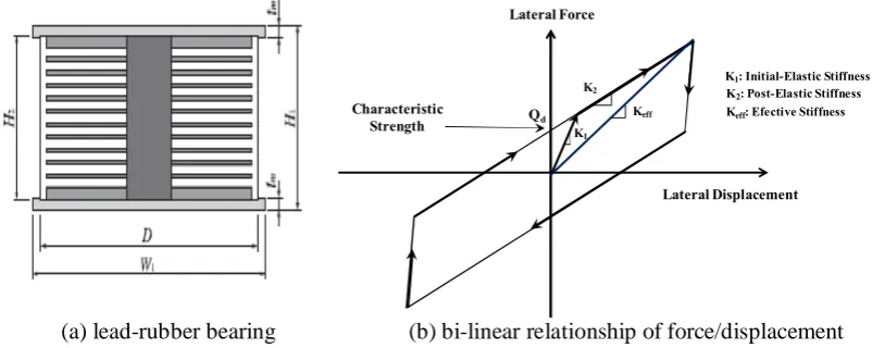
Base Isolation; Lead-Rubber Bearing (LRB) among the laminated elastomeric bearings as shown in the Figure 4(a) is employed for seismic isolation unit. The elastomeric material in the bearing is typically natural rubber, which has low horizontal stiffness and high vertical stiffness. The horizontal force/displacement relationship can be idealized as bi-linear shape shown in Figure 4(b). The number of total bearings is 121. Design parameters and their values for LRB are summarized at Table 1.
Input control motion; Seismic ground input motion is applied only with one horizontal direction at ground surface, whose peak ground acceleration scale is 0.3 g. The acceleration time history has been generated artificially using the spectral amplitude compatible to the USNRC R.G. 1.60 response spectra, and the plots of the acceleration time history and corresponding spectral accelerations for 5% damping are shown in Figures 5(a) and 5(b), respectively.
ANALYSIS RESULTS
To show the validation of the newly proposed procedures, some SSI analyses are performed, that is, a SSI analysis on the example model defined at previous section without base isolators, and a SSI analysis on the example model with base isolators having equivalent stiffness. The separated interface at all analyses becomes the ground surface between the mat foundation and soil region. The stiffness of LRB is simplified to effective stiffness and analysis results are obtained under linear behavior. The response results show the comparison results on DHFTD SSI analysis referencing the conventional frequency domain SSI analysis results. Figures 6(a) and 6(b) show the response spectra curves for the first and second analyses at the interested node, top of internal structure, in Figure 3. The analysis results from the procedures are well matched to the referencing results showing the reduced seismic responses due to seismic isolation effects.
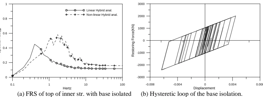
The analysis is extended to bilinear consideration of the isolator’s stiffness from equivalent stiffness still using the same example model. Figures 7(a) and 7(b) show response spectrum and force-displacement hysteresis loop, respectively, considering nonlinear effects of the isolators.
In this study, seismic response to the nonlinear SSI analysis of a NPP structure with base isolation were obtained using DHFTD analysis under the dynamic interaction concept of primary and secondary structures. It is shown that the new procedures suggested for the nonlinear seismic responses to the superstructure provide accurate and direct approach for a nonlinear SSI problem. The mathematical derivation of the procedures is simple and can be considered similar with the concept of substructure method of dynamic SSI, only except the cases that the consideration of an extraction of transfer functions from fully 3D SSI system, re-composition of coupled matrix and reconstruction of the separated model. The proposed procedure has also been implemented using KIESSI program.
Validation of the new procedures was identified through typical example analyses performed in linear system. Final example analysis showed nonlinear behavior results of the SSI system with base isolators based on the acceptance of the validation. The procedures can be finally said that it is an useful tool to get nonlinear seismic responses of the SSI structure with base isolation.
ACKNOWLEDGEMENT
The authors would like to thank the financial supports of the Ministry of Knowledge Economy and Korea Institute of Energy Technology Evaluation and Planning(KETEP) as a part the nuclear R&D program (NO. 2011T100200078)
REFERENCES
1. J. Wolf, "Soil-Structure Interaction Analysis in Time Domain", Prentice Hall, 1988.
2. S.K. Mohasseb and J. Wolf, "Recursive evaluation of interaction forces of unbounded soil in frequency domain", Soil. Dyn. Earth. Engrg., V8, p176-188, 1989.
3. G. R. Darbre, "Seismic analysis of non-linearly base-isolates soil-structure interaction reactor building b way of the hybrid frequency-time domain procedure", Earth. Engrg. Str. Dyn., V19, p725-738, 1990.
4. D. Bernal and A. Youssef, "A hybrid time-frequency domain formulation for non-linear soil-structure interaction", Earth. Engrg. Str. Dyn., V27, p673-685, 1998.
5. C.G. Seo, C.B. Yun, J.M. Kim, "Three-dimensional frequency-dependent infinite elements for soil-structure interaction", Engrg. Str., V29, p3106-3120, 2007.
6. J.S. Ryu, C. G. Seo, J.M. Kim, C. B. Yun, "Seismic response analysis of soil-structure interactive system using a coupled three-dimensional FE-IE method", Nuc. Engrg. Dgn., V240, p1949-1966, 2010
7. C.B. Yun, C.G. Seo, J.M. Kim, K.Y. Jung, “KAIST Infinite Element for Soil-Structure Interaction: KIESSI - User’s Manual”, Chonnam National University, 2012
8. R.A. Burdisso and M.P. Sign, "Multiple supported secondary system with dynamic interaction effcts", Earth. Engrg. Str. Dyn., V15, p1005-1022, 1987.
9. J. Lysmer, M. Tabatabaie-Raissi, F. Tajirain, S. Vandahi, and F. Ostadan, “A System for Analysis of Soil-Structure Interaction: SASSI - User's manual”, U. C. Berkeley, 1988
10. A.K. Chopra, “Dynamic of Structure”, Prentice Hall, 1995
Table 1. Bi linear properties of LRB Bearing
Diameter
Diameter of
Lead plug Target Period
Initial Stiffness
Post ratio
of stiffness Yield strength
Figure 1. total soil-structure interactive system with base isolation
Figure 2. separated system subjected multi-supported loads
Figure 3. Lumped beam stick model of nuclear power plant with base isolation
b: DOF of soil on near field
s: DOF of Str.
a : attached DOF on interface 1(ω) : unit control motion i: DOF of base isolation
e: DOF of near & far field interface e
G
a
G Infinite Element Region
Finite Element Region
Attached Finite Elements
Fixed Condition
a’ : DOF of excited forces
Rigid Links to Connect Stick to Foundation
Isolated Floor
Homogeneous Halfspace Vs= 609.6 m/s ρ = 2.08 Mg/m3
ν=1/3 βd=0.05
(a) lead-rubber bearing (b) bi-linear relationship of force/displacement
Figure 4. schematic lead-rubber bearing and bi-linearity curve of non-linearity
(a) time history of control motion (b) ground response spectrum of control motion
Figure 5. control motion
(a) FRS of internal str. by non-isolated SSI anal. (b) FRS of internal structure with isolated SSI anal.
Figure 6. Comparison study of FRS of LINEAR SSI analyses calculated by conventional method and proposed procedure respectively
Lateral Force
Lateral Displacement Qd
Characteristic Strength
K1: Initial-Elastic Stiffness K2
Keff K1
K2: Post-Elastic Stiffness Keff: Efective Stiffness
0 5 10 15 20
time -0.4 -0.2 0 0.2 0.4 A c c .( g )
0.1 1 10 100
Hertz 0 0.4 0.8 1.2 S p e c tr a l A c c .( g )
0.1 1 10 100
Hertz 0 2 4 6 8 S p e c tr a l A c c .( g )
FD SSI anal Present Hybrid SSI anal.
0.1 1 10 100
Hertz 0 0.2 0.4 0.6 0.8 1 S p e c tr a l A c c .( g )
(a) FRS of top of inner str. with base isolated (b) Hysteretic loop of the base isolation.
Figure 7. Responses of NON-linear base isolated SSI system calculated by DHFTD procedure
0.1 1 10 100
Hertz 0
0.2 0.4 0.6 0.8 1
S
p
e
c
tr
a
l
A
c
c
.(
g
)
Linear Hybrid anal. Non-linear Hybrid anal.
-0.008 -0.004 0 0.004 0.008
Displacement -3000
-2000 -1000 0 1000 2000 3000
R
e
s
to
ri
n
g
F
o
rc
e
(K
N