Mechanical Characteristics of the HANARO Fuel Capsule
KANG, Y.H.1), KIM, Y.J.1), Kim, B.G. 1), LEE, Y.S.2), KIM, H.S. 2) and CHOI, Y.J.2) 1) Korea Atomic Energy Research Institute, Korea
2) Chungnam National University, Korea
ABSTRACT
Flow-induced vibration problem of a fuel capsule of HANARO was studied by FEM analysis and modal tests in an air. FEM analysis shows that the boundary condition at the top part of the capsule main-body is found to be similar to the condition of hinge in which the first, second and third frequency of the capsule structure in air are 17.5Hz, 33.8Hz and 40.4Hz, respectively. From the vibration test in air, the first, second and third frequency of the capsule structure are 19.5Hz, 34.7Hz and 37.5 Hz. Calculated maximum displacement due to a flow induced vibration under normal operation conditions of HANARO is 0.073 mm at the position of the middle part of the capsule and 0.262 mm in the lower part of the capsule, respectively. Comparing empirical and theoretical results, the modification of a design feature of the lower part of the capsule will be needed with an additional vibration test in the HANARO reactor to evaluate the amount of interference with other nearby structures.
KEY WORDS: Research Reactor, Capsule, Vibration, Materials, Fuel, Irradiation tests INTRODUCTION
As a part of the national nuclear R&D program, various in-pile tests of an advanced PWR fuel are being carried out to compare them with conventional standard fuel. Since the capsule is subjected to flow-induced vibration (FIV) due to the flow of the primary coolant during the irradiation test, the structural integrity of the capsule in the reactor is an important research issue. Recently, a new way of loading for safe installation of a capsule to the HANARO core was suggested and reflected the design of the capsule to reduce the dynamic behavior caused by a FIV, which resulted in reviewing the new fuel capsule. However, the complexity of coolant flow in the forced convection area of the reactor induces a significant problem to directly obtain the flow-induced loads acting on the capsule structure. Although the safety test should be carried out by a field test under HANARO operating conditions, it has economical and technical problems. These kind of problems can be solved by choosing a research sequence through a modal test in air, analytical study by a finite element method and final field test.[1] Therefore, mechanical characteristics of a capsule in HANARO were studied to confirm its safety under flow-induced vibration. Emphasis is on comparison between analytical and empirical results based on a vibration test with a mock-up to evaluate the amount of interference with other nearby structures.
RESULTS AND DISCUSSION
Design and fabrication of mockup capsule for vibration test
The design concept of the capsule is taken to apply a universal principle(double containment concept) for experiments involving fissile in a research reactor. The capsule geometry is similar to the non-instrumented capsule and modified based on user requirements. The capsule consists of a basket, a bottom guide assembly, several mini capsules, flexible guide tube and a protection tube made of SUS 304 stainless steel tube. The protection tube is welded to the top of the basket(cylindrical pipe), and protects the instrumentation cables. A role of the bottom guide assembly attached at the bottom end of basket is to fix an instrumented capsule to the capsule-mounting spider of the HANARO reactor during irradiation test. The parts were designed for the specimen to be effectively cooled, monitor the indication of fuel failure and exposed in a neutron environment during irradiation tests. The design criteria of the capsule were selected considering HANARO operating conditions and fuel test objectives. The design criteria of the mini capsule were that the capsule was sustained at the working conditions of <800 oC and linear heat rating of <45 kW/m. With the design concepts, a mockup capsule for HANARO was designed and fabricated to perform a vibration test including pressure drop test and to optimize the capsule geometry compatible to the HANARO hydraulic conditions. The basket is 56mm in outer diameter, 2.5mm in thickness and 730mm in length. The capsule was loaded with test fuel pins of about 20 cm in length is 11.7mm in outer diameter and about 23cm in length and made of stainless steel. Fig. 1 is the photograph of the instrumented capsule used.
To maintain the structural integrity of the capsule during irradiation two kinds of stoppers(supporting system) are used. The upper stopper that is connected to the internal chimney has the role to grasp and support the capsule and the lower stopper that is connected to the reflector zone of the reactor has the role to push the top of the capsule main body
Transactions of the 17th International Conference on Structural Mechanics in Reactor Technology (SMiRT 17)
Prague, Czech Republic, August 17 –22, 2003
against the force induced from the up-flow of the coolants(12.7Kg/s) during irradiation. The fuel capsule can also be used in the periphery side of the in-core of the HANARO reactor.
Fig. 1. Capsule mockup for HANARO
Fig. 1. Capsule mock-up for HANARO
Analytical model and FEM analysis
The analysis model and jig construction for the embodiment of a real boundary condition is illustrated in Fig. 2. Total length of the analysis model is 4.591m and the applied boundary condition is loading at the in-core OR4 test hole of HANARO. In the irradiation test condition, an “A” and “B” part of the fuel capsule has fixed and hinged boundary condition, respectively. These boundary conditions are applied in the FEM analysis. The modal test using the impact exciting method is conducted in order to confirm the validity of the numerical model.
Fig. 2. Schematic diagram of analysis model
The FE analysis is conducted by an ANSYS commercial code[2]. In the FE-modeling, the beam 188 element is used at the rod tip, main body and the protection tube of the capsule in order to be a precise modeling. 3D Beam 188 element has 3 node and 6 degree of freedom per one node. The FE model of the fuel capsule is shown in Fig. 3. The subspace method is used in order to solve the eigen value problem.
Structural material of the fuel capsule is a stainless steel(SUS316) and its mechanical properties used in the analysis are as follows: Modulus of elasticity: 197Gpa, Poisson’s ratio: 0.3 and Density: 7,850kg/m3.
Modal test
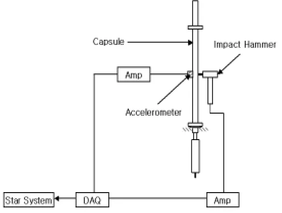
To verify finite element analysis and obtain the modal characteristics of the fuel capsule in air, a modal test using the impact exciting method is performed. Modal test equipment is composed of an impact hammer(PCB 086B03), accelerometer(PCB A352B18), data acquisition system(Bobcat DAQ5.32) and FFT analyzer(Star system). The schematic diagram of modal test is presented in Fig. 4. In the modal test, the fuel capsule is installed at the H-type beam of the building with a vertical direction to reduce the effect of deflection by weight. The measurement height(it corresponds to the height of 2 or 3 floors building) is very high, so each part of the fuel capsule should be measured: upper part, middle part and lower part, respectively. Prior to modal test, the exciting point is indicated for each part of the fuel capsule. One accelerometer attached at the point is used, which expected the vibration displacement occurred highly. For the middle part of the fuel capsule, the exciting point is divided into 9 equal parts and the accelerometer is attached at the middle point because the sectional shape is the same as the axial direction and has the clamped-hinged boundary conditions. In the lower part of the fuel capsule, the divided exciting point is 9 equal parts and the accelerometer is attached at the end of lower part. Finally, for the upper part of the fuel capsule, the exciting point is divided into 9 equal parts and the accelerometer is attached at the end of the upper part.
Fig. 4. Schematic diagram of the modal test equipments Comparison of modal test and FEM results
To check the validity of the FE-model, the computed natural frequencies are compared with those of the modal test results. The 1st, 2nd and 3rd natural frequencies of the fuel capsule with a clamped-hinge boundary condition from a modal test and finite element method are presented in the Table 1. In the Table 1, results of the finite element method show good agreement with those of the modal test within the maximum 11% variation. These variations are caused by the installation of the fuel element assembly in the modal test and acceptable. Fig. 5 (a), (b) and (c) are the 1st, 2nd and 3rd mode shapes of the fuel capsule from the finite element analysis results, respectively. In the 1st mode shape, the maximum displacement occurred at the edge of lower part of fuel capsule. For the 2nd mode shape, the maximum displacement occurred at the edge of the upper part of the fuel capsule. And in the 3rd mode shape, the displacement of middle part is increased. This is a typical mode shape of a beam with a clamped-hinged boundary condition.
Table 1. Comparison of the natural frequencies of fuel capsule by Modal test and FEM (Unit: Hz) Frequency
Order Number Modal test FEM
1st 19.5 17.5
2nd 34.7 33.8
(a) 1st mode shape (at 17.5Hz)
(b) 2nd mode shape (at 33.8Hz)
(c) 3rd mode shape (at 40.4Hz)
Fig. 5. Mode shapes of the fuel capsule from FEM analysis Flow induced vibration and displacement
horizontally excited by water. Because there is no method to predict the displacement of a beam with a free-hinge boundary condition vertically excited by fluids, the ratio of eigenvector of the middle part to the lower part of the capsule is used in order to predict the displacement of the lower part of the capsule caused by cooling water. The eigenvector has no real physical value, but this method has validity because the eigenvector ratio is potential energy relation of the structure[4]. However this logic needs more verification.
The natural frequency equation of the structure in the air and water is as follows, respectively[4].
1 2 w s k f m =
π , a a
m
k
f
π
2
1
=
(1)where, ms ( 2 2) 4 Do D Li s π
= − . and ma 2
4D Lo π
= . ,
The frequency ratio[3] is,
.
−
+
=
)
1
(
1
1
2 2 o i s a wD
D
f
f
.
.
0.811 (2)A fundamental frequency of the fuel capsule in the water, 14.2 Hz, is derived from eq. (2) and fundamental frequency of the fuel capsule in the air, 17.5 Hz, and the displacement caused by cooling water can be predict using the follow Paidoussis equation[3].
2 3
max
8
m
S
D
y
δ
π
.α.
=
(3)where, S=0.2and . =1.7( for the conservative design),
π.
δ
=
2
,2
(
)
(
)
2n s
f
f
f
H
.
α
=
,.
=0.099% (obtained by modal test),D
U
S
f
s=
,n
f
. fw, 0.3 / secU = m ,
2 2 2
)
(
2
)
(
1
1
)
(
+
−
=
n s n sf
f
f
f
f
H
.
Table 2. Maximum eigenvector of each part of the fuel capsule from FEM
Position
Frequency order number Center of middle part End of lower part
1st (17.5Hz) -0.27 0.97
2nd (33.8Hz) -0.11e-6 -0.17e-6
3rd (40.4Hz) 0.48 0.58
Table 3. Maximum displacement of each part of the fuel capsule under normal operation condition (Unit: mm) Position
Frequency order number Center of middle part End of lower part
1st (17.5Hz) 0.073 0.262
2nd (33.8Hz) 0.020 0.031
3rd (40.4Hz) 0.014 0.017
CONCLUSIONS
In order to predict the displacement of the capsule caused by flow-induced vibration, the vibration test and FEM analysis of the HANARO fuel capsule were performed. Major findings from this study are delineated below.
1. From the FEM analysis, the boundary condition at the top part of the capsule main-body is similar to the condition of hinge.
2. The first, second and third frequency of the capsule structure obtained by FEM analysis in air are 17.5Hz, 33.8Hz and 40.4Hz, respectively. Those obtained by a vibration test are 19.5Hz, 34.7Hz and 37.5 Hz, respectively.
3. Calculated maximum displacement caused by a flow induced vibration under the normal operation conditions of HANARO is 0.073 mm at the position of the middle part of the capsule and 0.262 mm at the lower part of the capsule. 4. Analysis results show that the design feature of the lower part of the capsule should be modified and additional vibration test using the modified capsule structure are needed. From this experiment, it is necessary to confirm that the redesigned capsule does not interfered with other nearby structures.
NOMENCLATURE
w
f : natural frequency in the water, a
f : natural frequency in an air, s
m : mass of the structure, a
m : added mass,
s
.
: density of the structure.
: density of water. iD : inner diameter of the capsule o
D : outer diameter of the capsule D: outer diameter of the structure,
0.2
S= : Strouhal No.,
. : mode shape coefficient
δ
: logarithmic decrement,α: resonance coefficient,
.
: damping ratio,D
U
S
n
f
: dominant frequency of the structure, U: flow velocity of coolant.( )
H f : Magnification factor
ACKNOWLEDGEMENT
This project has been carried out under the Nuclear R&D Program by MOST (Minister of Science and Technology). The authors would like to express their appreciation to the Ministry of Science Technology (MOST) of the Republic of Korea for support of their work through the mid- and long-term Nuclear R&D Project.
REFERENCE
[1] J. S. Ryu, Y.H. Kang, et al., Vibration Test Report on the Instrumented Capsule for Material Irradiation Test, KAERI/TR-2386, 2003.
[2] Swanson Analysis Systems Inc., ANSYS User’s Manual, 1999.
[3] H. J. Connors, Vortex Shedding Excitation and the Vibration of Circular Cylinders, J. Fluid Mech., Vol.52, pp. 47~73, 1981.