Banothu Venkati
Assistant professor Dept. of Civil Engineering, Madhira institute of Technology and science, Telangana, India
Abstract: This paper affords a simplified analytical technique for the assessment of the seismic performance of masonry infilled RC frames. The proposed approach has been based on the consequences of an extended analytical and experimental have a look at that taken into consideration non-ductile RC frames designed according to the constructing practice in California in the 1920. The experimental outcomes from a quasi-statically tested, 2/3-scale, single-tale, single-bay the frame was used for the validation of these days developed FE version which could correctly predict the conduct of those structures. The confirmed FE model changed into employed in parametric studies to discover they have an impact on of the longitudinal and vertical reinforcement, gravity load, and frame issue ratio.
Keywords- Masonry infills, RC Frames, Simplified Modelling, Seismic Assessment, Parametric Study
I. INTRODUCTION
Reinforced concrete (RC) body buildings with masonry infill partitions had been widely built for industrial, business and multi-own family residential uses in seismic-prone regions global. Masonry infill generally includes brick masonry or concrete block partitions, built between columns and beams of an RC body. These panels are typically not taken into consideration in the layout procedure and dealt with as non-structural additives. In The USA like India, Brick masonry infill panels were extensively used as interior and outside partition walls for aesthetic motives and functional desires. Though the brick masonry infill is taken into consideration to be a non-structural element, however, it has its personal power and stiffness. Hence if the effect of brick masonry is considered in analysis and layout, huge growth in electricity and stiffness of ordinary structure may be discovered. Present code, IS 1893(Part-I): 2000 of practice does now not encompass the provision of taking into consideration the effect of infill. It may be
understood that if the effect of infill is taken into account within the evaluation and design of the body, the resulting shape may be appreciably distinct. Significant experimental and analytical studies are suggested in various kinds of literature, which attempts to provide an explanation for the conduct of infilled frames. Moreover, infill, if present in all stories offers a huge contribution to the strength dissipation capability, decreasing appreciably the most displacements. Therefore the contribution of masonry is of notable significance, despite the fact that strongly relying on the traits of the floor motion, particularly for frames which have been designed without considering the seismic forces. When surprising exchange in stiffness takes area along the constructing top, the tale in which this drastic change of stiffness takes place is called a gentle tale. According to IS1893(Part-I): 2000, a tender tale is the one in which the lateral stiffness is much less than 50% of the story above or below.
Another vital difficulty is related to the numerical simulation of infilled frames. The extraordinary strategies for idealizing this structural version may be divided into neighborhood or micro-fashions and simplified macro models. The first institution entails the models, wherein the structure is divided into several elements to recall of the local impact in the element, whereas the second one organization consists of simplified fashions based on a bodily know-how of the conduct of the infill panel. In this have a look at the power and stiffness of the brick masonry infill is taken into consideration and the brick masonry infill is modeled the usage of the diagonal strut. The diagonal strut has been modeled using software package SAP2000. The evaluation is done using “Linear static analysis” for knowledge the improvement in stiffness parameters.
II. RELATED WORKS
Previous experimental studies also carried out on the behavior of RC frames with in-fills and the modeling,
analysis of the RC frame with and without in-fills. StaffordSmith B [1] used an elastic theory to endorse the effective width of the equivalent strut and concluded that this width ought to be a function of the stiffness of the in-fill with appreciating to that of bounding frame. By analogy to a beam on elastic basis, he described the dimensionless relative parameters to determine the degree of body in-fill interplay and thereby, the effective width of the strut. Also defined the method of empirical equations for the calculation of infill wall parameter as strut model like contact length of the strut, the powerful width of the strut. Holmes [2] was the primary in changing the infill by an equal pin-jointed diagonal strut. He proposed the modeling of infill wall as the diagonal strut and finding the powerful width and contact period of the diagonal strut. Das and C.V.R. Murty [3] executed non-linear pushover evaluation on five RC body buildings with brick masonry in-fills. In-fills are observed to increase the strength and stiffness of the shape and reduce the drift capability and structural harm. In-fills reduce the overall shape ductility, however, increase the overall electricity. Building designed by using the equal braced body method confirmed better ordinary performance.
Amato et al. [4]mentioned the mechanical behavior of single story-unmarried bay in-stuffed frames done certain numerical research on in-crammed meshes has proved that in the presence of vertical loads it's far possible that a robust correlation between the size of the equal diagonal strut version and a single parameter, which relies upon on the characteristics of the gadget.
V.K.R.Kodur et al. [5]considered a 3 story RC frame building fashions for the analysis. These RC frames were analyzed for 3 cases i) Bare frame ii) Infilled frame iii) Infilled body with openings. Based on the evaluation consequences they observed that Base shear of an infilled body is more than infilled body with openings and bare body. The time length of the infilled body is much less as evaluate to the infilled frame with openings and naked frame. The natural frequency of infilled frame is more as examine to the infilled frame with openings and bare body.
Haroon Rasheed Tamboli [6]taken into consideration the bare body and infill model systems and plays the
seismic evaluation to see the version in both the syst ms. His paper says that in presence of infill wall, it influences the seismic behavior of frame structure to massive quantity and the infill will increase the energy and stiffness in the structure. A.Mohebkhah et al. [7] completed styles of numerical modeling strategies to stimulate the in-aircraft non-linear static conduct of infilled frames with openings with micro and macro modeling. Also analyzed the version of infill frame as three-strut model and performed pushover evaluation to check the capability of systems throughout non-linear evaluation wherein three-strut version suggests more energy and stiffness at some stage in the robust floor motion and perform properly whilst stiffness of infill wall is taken into consideration. Neelima Patnala VS and Pradeep Kumar Ramancharla [8] taken into consideration 3 sets of 2D regular moment resisting frames with and without unreinforcedmasonry infill walls (with and without openings) are considered. Applied Element Method is used to version the frames and nonlinear static pushover analysis is done to attain the capacity curves. It is discovered that the power of the frame with infill is 10times greater than the normal bare frame, the ductility of the frame increases with the addition of the infill walls. Increase in number of stories, the power of the naked body increases, manifestly, whereas the strength of the body with infill decreases it can be stated that the difference in behavior of bare frame should not best be validated on a single story but to be checked with different number of stories
III. THE PROPOSED APPROACH
(a) Elevation of an exterior frame of the prototype (dimensions in m).
(b) design of single-bay, single story frame for large-scale specimen considered here (dimensions in cm)
Figure 1. Design of RC frame.
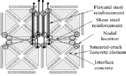
Numerical models: The specimen shown in Figure 1(b) was modeled with the finite element method in FEAP (Taylor 1997). The concrete columns and masonry infills are modeled with the modeling schemes developed by Stavridis and Shing (2010) which are shown in Figure 2.
(a) Finite element discretization scheme for RC members
(b) Finite element discretization scheme for masonry infill
Figure 2. Finite element modeling schemes.
Based on the findings of the parametric study, a method to derive a simplified lateral force-vs.-drift behavior has been developed. The constructed curve is not an accurate representation of the actual behavior and cannot provide the amount of information on the structural performance that a detailed finite element analysis can provide. However, it is a simple yet efficient way to conservatively estimate the basic features of the structural behavior in six steps.
Step 1: Initial Stiffness, Kini
The initial stiffness of an uncracked infilled frame can be calculated with the consideration of a shear beam model with the following expression proposed by used by Fiorato et al. (1970)
in which hb is the height of the composite column measured from the top of the foundation to the midheight of the RC beam, Ec is the modulus of elasticity of concrete, and Ice is the equivalent moment of inertia of the transformed section of a transformed concrete section. I ce depends on the ratio of elastic moduli of concrete and masonry and geometry of the cross-section. Alternatively, the modulus of elasticity of masonry can be used in Equation 2, if the composite cross section is transformed to an equivalent masonry cross section.
Step 2: Yield strength, Vy
In the cases examined in the previous sections, the yield point in the force-vs.-drift curve coincides with the separation and sliding between the infill and the RC frame. The drift and force at which the separation occurs depend on the bond quality and cohesion between the two, as well as the vertical force. The frame-infill is a statically indeterminate system and this force changes as the structure deforms.
Step 3: Peak strength, Vmax
The majority of the frames considered in this study reached the peak strength before the shear sliding crack in the infill, or prior to the shear failure of one of the columns. Knowing the failure mechanism a priori can help determine the strength of the structure. However, without conducting an experiment or a finite element analysis, there is no reliable tool able to predict the actual failure mechanism or strength due to the complexity of the failure mechanism. Moreover, even if the mechanism could be predicted, the distribution of vertical forces between the RC columns and the masonry wall would remain unknown as the vertical forces change along the height of the wall and columns. Therefore, a precise calculation of the peak load with a simple model is not possible. However, the peak strength of the infilled frame can be estimated based on a number of simplification assumptions.
In the method proposed here, the load on the critical cross sections of the columns is considered. These are the top cross section of the windward column and
bottom cross section of the leeward column. The externally applied vertical load can be distributed on the columns and the masonry wall in proportion to their vertical stiffness. Then, a pair of vertical forces in the columns resisting the overturning moment can be considered. These forces are a function of the lateral strength of the structure and cannot be known if the lateral strength is not known. However, it can be assumed that the force in the windward column is the force required to cancel the compressive force due to the externally applied vertical load. An equal compressive force can be considered to act on the leeward column. The shear strength of the columns can be estimated based on the formulas provided by ACI. The total resistance of the infilled frame can be assumed to be equal to the summation of the shear resistance of the columns, the cohesion along the bed joints and the frictional force resulting from the portion of the vertical load carried by the infill.
Step 4: Drift at peak strength, Vmax
The drift at peak strength cannot be easily calculated with a simplified approach as it depends on a number of parameters, including the interaction between the frame and the infill.
Step 5: Residual strength , Vres
The residual strength can be defined as the strength of the structure when a dominant shear crack has developed in the infill and propagated through the RC columns. Based on the analyses presented here, this is a worst case scenario as in some cases only one column failed due to shear.
Step 6: Drift at which the residual strength is reached, Vres
The drift at which the residual strength is reached depends on the convention used to define the residual strength of the structure since in many cases a sudden load drop is followed by mild declining slopes.
V. CONCLUSION
the proven finite element model. The effects of the look at imply that the most influential parameter is the issue ratio of the panel as it can trade the conduct of the shape remarkably. The externally carried out vertical load is likewise influential; however it does now not affect the preliminary stiffness and its effect on the failure mechanism is most effective glaring while its cost dropped to 0, that's an extreme case. The longitudinal reinforcement has restrained impact on the structural behavior, even as the quantity of transverse reinforcement can have an effect on the ductility but now not the strength of the shape.
REFERENCES
[1]. a. Stafford Smith B, Lateral stiffness of infilled frames, Journal of Structural division, ASCE,88 (ST6), 1962, pp. 183-199. b. Stafford Smith B. Behaviour of Square Infilled Frames. Proceedings of the American Society of Civil Engineers, Journal of Structural Division, 92, no STI, 381-403, 1966. c. Stafford Smith B, Carter C. A method of analysis for infill frames. Proc. Inst. Civil Engineering, 1969.
[2]. Holmes M. Steel frames with brickwork and concrete infilling. Proceedings of the Institution of Civil Engineers 19, 1961.
[3]. A. DAS D AND MURTY C V R, Brick Masonry Infills in Seismic Design of RC Frame Buildings: Part 2- Behaviour, The Indian Concrete Journal, 2004.
[4]. A. AMATO G, CAVALERI L, FOSSETTI M, AND PAPIA M, Infilled Frames: Influence of Vertical Load on The Equivalent Diagonal Strut Model, The 14th World Conference on Earthquake Engineering, Beijing, China, 2008.
[5]. V.K.R.Kodur, M.A.Erki and J.H.P.Quenneville “Seismic analysis of infilled frames” Journal of Structural Engineering Vol.25, No.2, July 1998 PP 95 -102.
[6]. Haroon Raheed Tamboli and Umesh N.Karadi, Seismic Analysis of RC Frame Structures With and Without Masonary Walls, Indian Journal of Natural Sciences, Vol.3/Issue14, Oct.2012.
[7]. A.Mohebkhah, A.A.Tanimi, and
H.A.Moghadam, A Modified Three-Strut (MTS) Model for Masonry-InfilledSteel Frames with Openings, Journal of Seismology and Earthquake Engineering, Vol.9, No.1,2 , Spring and Summer 2007.
[8]. Patnala V S Neelima, Ramancharla Pradeep Kumar, Seismic Behaviour of RC Frame with URM Infill: A Case Study, International Journal of Education and Applied Research (IJEAR), Vol.4, Issue Spl-2, Jan-June 2014.
[9]. ACI 318-08 (2008). “Building Code Requirements for Structural Concrete (ACI 318-08) and Commentary.” Farmington Hills, Mi.
[10]. Al-Chaar, G. (2002), “Evaluating Strength and Stiffness of Unreinforced Masonry Infill Structures.” Report No. ERDC/CERL TR-02-1, US Army Corps of Engineers.
[11]. ASCE/SEI 41-06. (2006). “Seismic Rehabilitation of existing buildings.” ASCE, New York.
[12]. Attard, M. M., A. Nappi, and F. Tin-Loi (2007). “Modeling fracture in Masonry.” J. Struct. Eng., ASCE, Vol. 133(10), 1385-1392.
[13]. Blackard, B., K. Willam, and S. Mettupulayam (2009). “Experimental observations of masonry infilled RC frames with openings.” ACI Special Publication SP-265, American Concrete Institute, Farmington Hills, MI.