A Fuzzy Based Two Level STATCOM for
High-Power Applications
B. Prabhakar
M-tech Student Scholar Department of Electrical & Electronics Engineering, Anurag Engineering
College, aushapur, (vill); Ranga reddy (Dt); Telangana, India
Mrs R Rekha
Associate Professor Department of Electrical & Electronics Engineering, Anurag Engineering College,
aushapur, (vill); Ranga reddy (Dt); Telangana, India
Abstract-
This paper presents a special gating
pattern swapping technique for cascaded
multilevel inverter, which is used for STATCOM.
By using this technique besides minimizing the
harmonic level, the inverter unit fundamental
output voltages are, equalized. Therefore, all the
inverter units in each phase leg can equally
share the exchanged active and reactive power
with the utility grid. This greatly helps the
dc-link voltages balancing control. PI or Fuzzy
Control is employed for improving performance.
The dc-link voltages of the inverters are
regulated at different levels to obtain four-level
operation. In this paper two level fuzzy based
STATCOM by using MATLAB/SIMULATION
software. The simulation study is carried out in
MATLAB/SIMULINK to predict the performance
of the proposed scheme under balanced and
unbalanced supply-voltage conditions.
Index Term s —DC-link voltage balance,
multilevel inverter, Power quality (PQ), static
compensator (STATCOM), Fuzzy controller.
I. INTRODUCTION
The rapid growth in electrical energy use, combined with demand for low cost energy, has gradually led to the development of generation sites remotely located from the load center. The generation of bulk power at remote locations necessitates the use of transmission line to connect generation sites to load centers. With long distance ac power transmission and load growth, active control of reactive power is indispensable to stabilize the
power system and to maintain the supply voltage. The static synchronous compensator (STATCOM) using voltage source inverters has been accepted as a competitive alternative to the conventional Static VAr compensator (SVC) using thyristor-controlled reactors STATCOM functions as a synchronous voltage source. It can provide reactive power compensation without the dependence on the ac system voltage. By controlling the reactive power, a STATCOM can stabilize the power system, increase the maximum active power flow and regulate the line voltages. Faster response makes STATCOM suitable for continuous power flow control and power system stability improvement. The interaction between the AC system voltage and the inverter-composed voltage provides the control of the STATCOM var output [7] [8]. When these two voltages are synchronized and have the same amplitude, the active and reactive power outputs are zero.
pattern is used for maintain the dc capacitor charge balance and equalize the current stress of the switching device.
In this paper, a static var compensation scheme is proposed for a cascaded two-level inverter-based multilevel inverter. The topology uses standard two-level inverters to achieve multilevel operation. The dc-link voltages of the inverters are regulated at asymmetrical levels to obtain four-level operation. To verify the efficacy of the proposed control strategy, the simulation study is carried out for balanced and unbalanced supply-voltage conditions.
II. CASCADED TWO-LEVEL INVERTER-BASED MULTILEVEL STATCOM.
Fig. 2 shows the circuit topology of the cascaded two-level inverter-based multitwo-level STATCOM using standard two-level inverters. The inverters are connected on the low-voltage (LV) side of the transformer and the high-voltage (HV) side is connected to the grid. The dc-link voltages of the inverters are maintained constant and modulation indices are controlled to achieve the required objective. The proposed control scheme is derived from the ac side of the equivalent circuit which is shown in Fig.3. In the figure, 𝑣𝑎′, 𝑣𝑏′ and 𝑣𝑐′ are the source voltages
referred to LV side of the transformer ra, rb, and rc are the
resistances which represent the losses in the transformer and two inverters, and are leakage inductances of transformer windings, and are the output voltages of inverters 1 and 2, respectively. Are the leakage resistances of dc-link capacitors and, respectively. Assuming and applying
KVL on the ac side, the dynamic model can be derived using as
(1)
Equation (1) represents the mathematical model of the cascaded two-level inverter-based multilevel STATCOM in the stationary reference frame. This model is transformed to the synchronously rotating reference frame. The d-q axes reference voltage components of the converter and are controlled as
(2)
(3) Where vd′ is the -axis voltage component of the ac source and id′ , iq′ are - axes current components of the cascaded
inverter, respectively. The synchronously rotating frame is aligned with source voltage vector so that the -component of the source voltage vq′ is made zero. The control
parameters and are controlled as follows:
(4) The -axis reference current is 𝑖𝑑∗ obtained as
(5) Where𝑣𝑑𝑐1∗ , 𝑣𝑑𝑐2∗ and are the reference and actual dc-link
voltages of inverters 1 and 2, respectively. The q-axis reference current 𝑖𝑞∗is obtained either from an outer
voltage regulation loop when the converter is used in transmission-line voltage support [5] or from the load in case of load compensation.
A 100Mvar STATCOM device is connected to the 230-kV (L-L) grid network. Fig.2 shows the single line diagram representing the STATCOM and the host sample grid network. The feeding network is represented by a thevenin equivalent at (bus B1) where the voltage source is represented by a kV with 10,000 MVA short circuit power level with a followed by the transmission line connected to bus B2. The STATCOM device comprises the voltage source converter-cascade model connected to the host electric grid. 7-level is chosen here for STATCOM. It is connected to the network through the coupling transformer. The dc link voltage is provided by the capacitor C, which is charged from the ac network. The decoupled current control system ensures full dynamic regulation of the bus voltage and the dc link voltage.
Fig.1.Single Line Diagram Representing STATCOM.
Fig.2. Cascaded two-level inverter-based multilevel STATCOM
Fig.3.Equivalent circuit of the cascaded two-level inverter-based multilevel STATCOM.
A. Control strategy
The control block diagram is shown in Fig.4. The unit signals and are generated from the phase-locked loop (PLL) using three-phase supply voltages. The converter currents (ia′ , ib′ , ic′) are transformed to the synchronous
rotating reference frame using the unit signals. The switching frequency ripple in the converter current components is eliminated using a low-pass filter (LPF). From ( vdc 1∗ + vdc 2∗ ) and iq∗ loops, the controller generates –
axes reference voltages, ed∗ and eq∗ for the cascaded
inverter. With these reference voltages, the inverter supplies the desired reactive current iq∗ and draws required
active current ( iq′ ) to regulate total dc-link voltage vdc 1∗ +
vdc 2∗ However, this will not ensure that individual dc-link
voltages are controlled at their respective reference values. Hence, additional control is required to regulate individual dc-link voltages of the inverters.
Fig.4.Control block diagram.
B. DC link balance controller
The resulting voltage of the cascaded converter can be
given as , where and
.The active power transfer between the source and inverter depends on and is usually small in the inverters supplying var to the grid [1]. Hence, 𝛿 can be assumed to be proportional to eq.
Therefore, the q-axis reference voltage component of inverter-2 𝑒𝑞2∗ is derived to control the dc-link voltage of
inverter-2 as
(6) The q-axis reference voltage component of inverter-1 𝑒𝑞1∗
is obtained as
(7)
The dc-link voltage of inverter-2 is controlled at 0.366 times the dc-link voltage of inverter-1 [9]. It results in four-level operation in the output voltage and improves the harmonic spectrum.
C. Unbalanced conditions
eliminated or reduces the unbalance in the grid voltage. In the latter case, STATCOM needs to supply large currents since the interfacing impedance is small. This may lead to tripping of the converter.
The negative-sequence reference voltage components of the inverter 𝑒𝑑𝑛∗ and 𝑒𝑞𝑛∗ are controlled similar to
positive-sequence components in the negative synchronous rotating frame as
(8)
(9)
III. CONTROL SCHEME FOR STATCOM
To regulate the system voltage and reactive power compensation PI control is employed. To enhance the transient stability fuzzy control is employed.
A.PI Control for STATCOM
Auxiliary control method is used to regulate the system voltage and to regulate the reactive power current effectively. Fig 5 shows the controller for STATCOM. The output of the PLL is the angle that used to measure the direct axis and quadrature axis component of the ac three-phase voltage and current. The outer regulation loop Comprising the ac voltage regulator provides the reference current (Iqf) for the current regulator that is always in quadrature with the terminal voltage to control the reactive power. The voltage regulator is a PI controller. A supplementary regulator loop is added using the dc capacitor voltage. The dc side capacitor voltage charge is chosen as the rate of the variation of this dc voltage. The current regulator controls the magnitude and phase of the voltage generated by the PWM converter (Vq, Vd) from the Idf and Iqf reference currents produced, respectively, by the dc voltage.
Figure 5. PI Controller for STATCOM.
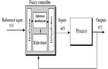
IV. INTRODUCTION TO FUZZY LOGIC CONTROLLER
A new language was developed to describe the fuzzy properties of reality, which are very difficult and sometime even impossible to be described using conventional methods. Fuzzy set theory has been widely used in the control area with some application to dc-to-dc converter system. A simple fuzzy logic control is built up by a group of rules based on the human knowledge of system behavior. Matlab/Simulink simulation model is built to study the dynamic behavior of dc-to-dc converter and performance of proposed controllers. Furthermore, design of fuzzy logic controller can provide desirable both small signal and large signal dynamic performance at same time, which is not possible with linear control technique. Thus, fuzzy logic controller has been potential ability to improve the robustness of dc-to-dc converters. The basic scheme of a fuzzy logic controller is shown in Fig 5 and consists of four principal components such as: a fuzzy fication interface, which converts input data into suitable linguistic values; a knowledge base, which consists of a data base with the necessary linguistic definitions and the control rule set; a decision-making logic which, simulating a human decision process, infer the fuzzy control action from the knowledge of the control rules and linguistic variable definitions; a de-fuzzification interface which yields non fuzzy control action from an inferred fuzzy control action [10].
Fig.6. General structure of the fuzzy logic controller on closed-loop system
Fig.7. Block diagram of the Fuzzy Logic Controller (FLC) for dc-dc converters
A. Fuzzy Logic Membership Functions:
The dc-dc converter is a nonlinear function of the duty cycle because of the small signal model and its control method was applied to the control of boost converters. Fuzzy controllers do not require an exact mathematical model. Instead, they are designed based on general knowledge of the plant. Fuzzy controllers are designed to adapt to varying operating points. Fuzzy Logic Controller is designed to control the output of boost dc-dc converter using Mamdani style fuzzy inference system. Two input variables, error (e) and change of error (de) are used in this fuzzy logic system. The single output variable (u) is duty cycle of PWM output.
Fig. 8.The Membership Function plots of error
Fig.9. The Membership Function plots of change error
Fig.10. The Membership Function plots of duty ratio B. Fuzzy Logic Rules:
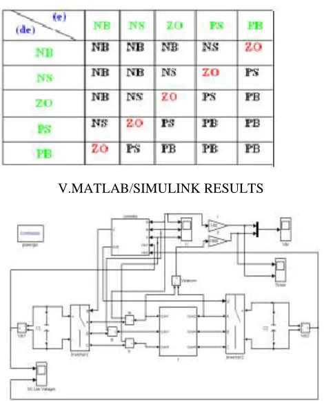
The objective of this dissertation is to control the output voltage of the boost converter. The error and change of error of the output voltage will be the inputs of fuzzy logic controller. These 2 inputs are divided into five groups; NB: Negative Big, NS: Negative Small, ZO: Zero Area, PS: Positive small and PB: Positive Big and its parameter [10]. These fuzzy control rules for error and change of error can be referred in the table that is shown in Table II as per below:
Table II
Table rules for error and change of error
V.MATLAB/SIMULINK RESULTS
Fig. 12. Reactive power control: Source voltage and inverter current.
Fig.13. Reactive power control: DC-link voltages of two inverters
Fig.14. Load compensation: Source voltage and inverter current.
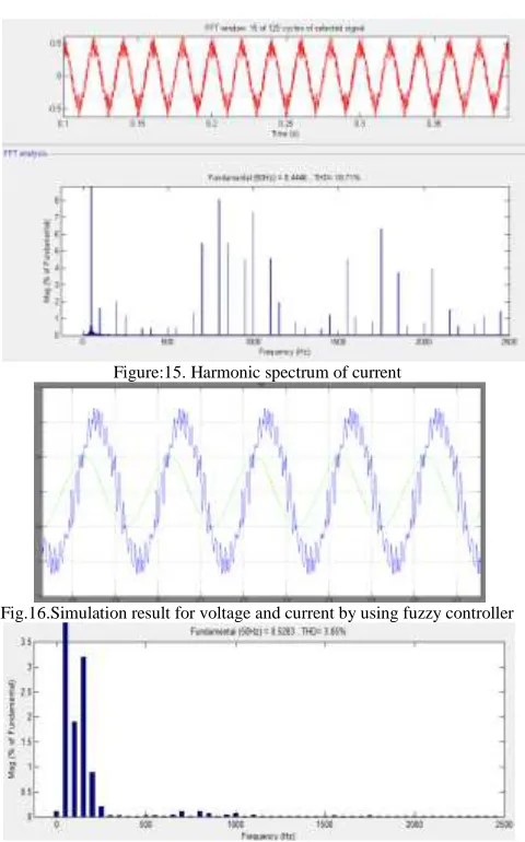
Figure:15. Harmonic spectrum of current
Fig.16.Simulation result for voltage and current by using fuzzy controller
Fig.17.harmonic spectrum for source current by using fuzzy controller
V.CONCLUSION
REFERENCES