Speed Control of Induction Motor Drives
using Digital Signal Controllers (DSC)
P.Sarojini1, R.Issan Raj2
Assistant Professor, Dept. of EIE, Valliammai Engineering College, Kancheepuram, Tamilnadu, India1
PG Student [C&I], Dept. of EIE, Valliammai Engineering College, Kancheepuram, Tamilnadu, India2
ABSTRACT: Induction motor is widely used in small scale as well as the large scale industries. In industrial sector, there prevails a major drawback in speed controlling of three phase induction motor drives when subjected to heavy loads. These are called as disturbances in a motor. A motor can have both the internal disturbance as well as the external disturbance. To eliminate these types of disturbance a microcontroller that can work with all capabilities of a Digital Signal Processor (DSP) is employed. The digital signal controllers are coded with the vector control or field oriented control scheme to control the speed of the three phase induction motor. The dsPIC microcontroller is a 16-bit micro controller unit ((MCU) with computation and throughput capabilities of DSP processor in single core. A driver circuit of closed loop IGBT is used to limit the fluctuations of current in the induction motor.
KEYWORDS: Squirrel cage induction motor, IGBT gate driver, dsPIC microcontroller, vector control, isolation and
buffer.
I.INTRODUCTION
The induction motor is the widely used in large scale industries due to its reliability, rugged construction, high efficiency, good power factor and it has a simple starting arrangement. Numerous methods are available for the control of induction motor drives exhibiting nonlinear character. When it is related to the speed control, the following facts are to be studied since it is an extreme drawback due to the low starting torque and its associated proportional increase in load.
An induction motor is a nonlinear time varying system, whose state transient measuring is much difficult resulting towards difficultly in controlling. Here, the electrical energy is converted into mechanical energy that has a high performance drives system modifying the machine performance, dynamic model and parameter variations. An AC induction motor has a fixed outer portion, called the stator and a rotor that spins inside with a carefully engineered air gap between the two. Virtually all electrical motors use magnetic field rotation to spin their rotors. A three-phase AC induction motor is the only type where the rotating magnetic field is created naturally in the stator because of the nature of the supply [2]. DC motors depend either on mechanical or electronic commutation to create rotating magnetic fields. A single-phase AC induction motor depends on extra electrical components to produce this rotating magnetic field. Depending upon the type of control mechanisms like scalar control [2,3], indirect torque control[4,6], direct torque control[7,10], field acceleration method, universal field orientation, direct self control [11] the current regulation in the loops are studied.
II. INDUCTION MOTOR DRIVES
Induction motor are categorized on the basis of the windings and their rotating winding which has non ideal winding distribution for neglecting the effects of slots and apace harmonics. The classified elements are, 1) cage or wound rotor (dually fed) and 2) rotating or linear. The single phase and three phase motor are prominently employed throughout the industrial sectors. Among them the three phase winding plays a vital role in controlling the motion of the associated systems.
methods employed in AC machines are 1) scalar control (V/F), 2) vector control or field oriented control (FOC) and 3) direct torque control (DTC). The proposed scheme is experimented with the vector control mechanism.
A.Vector control
Vector control deals with the variation of the control variables due to the changes in their magnitude and phase orientation. Unlike the scalar control method, whose variations in the control variables are only due to the changes in the magnitude values of the set point. The proposed method is well known as decoupling, orthogonal or transvector control.
The limiting factor in the scalar control like inherent coupling effect giving sluggish response and the system instability to the higher order effect are sustained in this proposed scheme. There are two general methods of vector control, studied and schematized as 1) direct or feedback method (by Blanschke) and 2) indirect or feed forward method (by Hasse). Both the scheme generates a unit vector namely, cosine and sine angles for the control stator and rotor flux that provides natural decoupling air gap and coupling effect which has to be compensated by the decoupling compensation current.
At the low frequency response, the voltage signals are very low because of which the ideal integration is difficult since its estimated signal accuracy is reduced. In indirect vector control the torque producing components are controlled only after the transformation is undergone and not by its main reference input. The flux measurement is carried out using flux sensing coil or hall devices.
Salient features of the vector control method are:
1. Frequency of the drive is not directly controlled as in scalar control.
2. It is a self controlled one, where the frequency and phase are indirectly controlled with the help of the unit vector.
3. No instability problems as such in scalar control while crossing the operating point beyond the breakdown or
regenerative torque.
4. Transient response is fast because ideal vector control is impossible due to delays in converters, signal processing and parameter variation effect.
5. Speed control is possible in four quadrants using forward monitoring condition and reverse monitoring
condition. The direct method of vector control is very difficult to operate successfully at a low frequency range.
III. IGBT GATE DRIVER
The electrical drives are of two types,
1. Open loop system
2. Closed loop system
The open loop doesn’t contain the speed limiter while the closed loop has. There are two types of electrical drives namely 1.) Speed loop and 2.) Torque loop. Many applications require the speed of an AC motor to vary.
The easiest way to vary the speed of an AC induction motor is to use an AC drive to vary the applied frequency. Operating a motor at other than the rated frequency and voltage affect both motor current and torque.
Power diodes provides uncontrolled rectification of power and are used in applications such as electroplating, anodizing, power supplies (AC and DC) and variable frequency drives. They are also used in feedback and freewheeling functions of the converters and snubbers.
The power diodes are classified on the basis of
1. standard or slow recovery diode
2. fast recovery diode
1.) Insulated Gate Bipolar Transistor
Extremely popular in power electronics upto medium power (a few Kw too few Mw) range and are applied extensively in dc/ac drives and power supply system. It is the combination of BJT (upper range) and GTO (lower range).
IGBT is basically a hybrid MOS-gated turn on/off bipolar transistor that combines the advantage of both a MOSFET and BJT. It has high current density. IGBT uses trench gate technology to reduce the conduction drop further. IGBT intelligent power modules (IPMS) are available with built in-gate drivers, control and protection for up to a several
hundred KW power rating. The Insulated Gate Bipolar Transistor is a cross between a conventional Bipolar Junction
Transistor (BJT) and a Field Effect Transistor (MOSFET).
The other types of power semiconductor devices are based on silicon material as,
diode
thyristor/ silicon controlled rectifier (SCR)
triac
gate turn-off thyristor (GTO)
bipolar junction transistor (BJT)
power MOSFET
static induction thyristor (SIT)
MOS-controlled thyristor (MCT)
Integrated gate commutated thyristor (IGCT)2.) Diode
Diodes are used for uncontrolled rectification of power. They are used in freewheeling and feedback functions of converters and snubbers. Its structure is [P-I-N] i.e. P-N structure with intrinsic semiconductor layer and sustained reverse voltage.
The diode characteristics are given below as,
Under forward biased condition: represented by a junction offset drop and series equivalent resistance and the conduction loss in the junction temperature are cooled by heat sink.
Under reverse biased condition: small leakage current flows due to minority carriers which gradually increase with voltage. If reverse voltage exceeds a threshold value called the breakdown voltage, the device gaps through avalanche breakdown. Under reverse current is large and the diode is destroyed by heating due to large power dissipation in the junction.
3.) Gate driver
The gate drives is a power amplifier that increases the current gain of the high powered transistor associated with the motor. It accepts a low power input from the controller unit and amplifies it to the level of the driver circuit. The gates driver is also provided with the level shifter.
IV. VECTOR CONTROL DESIGN
The characteristic features of induction machines are based on the factors like rugged, reliable and their availability in the ranges of fractional horse power (FHP) to multi megawatt capacity. The single phase induction motor produces low power FHP. In induction machines, the stator and rotor core are made up of laminated ferromagnetic steel sheets. The torque produced in the induction motor is by the sweeping magnetic field, whose slip frequency and the synchronous speed in RPM is denoted using the equations provided below.
fe=we /2π. (2)
Where,
Ne – synchronous speed in rpm
fe – stator frequency in Hz
The torque expression is,
Te = π (p/2) lrBpFpsinδ (3) A. Axes transformation
The three phase (3Φ) stationery reference frame (as-bs-cs) variables into two phase (2Φ) stationary reference frame (ds -qs) variables and then transform these to synchronous reference frame (de-qe) and vice versa.Principle of vector control deals with the two different mechanism, one is controlling and another is machine performance. The indulging terminals also perform the function of transformer and inverse transformer.
B. Dynamic modelling
The dynamic modelling of d-q axis of an induction machine is taken from the per phaseequivalent circuit that are valid in steady state condition. The transient behaviour is analyzed by the feedback loop provided in the adjustable speed drive. The dynamic performance of an AC induction machine is complex because three phase motor winding move with respect to the three phase stator winding.
To overcome the problem in the time varying parameters R.H.Park in 1920 formulated a change in a variables which, in effect replaced the variables (V/I & flux) associated with stator winding of a synchronous machine with variables associated with fictitious windings rotating with the rotor synchronous speed.
C. General methods of vector control
The two general methods of vector control are
1.) Direct or feedback method (by Blanschke) 2.) Indirect or feed forward method (by Hasse)
The two method generates a unit vectors namely sinθeand cosθe. Orientation of ids with rotor flux ψr, air gap flux ψm or stator flux ψs. The rotor flux induces natural decoupling while the air gap or stator flux gives coupling effect which has
to be compensated by a decoupling compensation current.
The flux produced in the d-q axis is generated from the machine terminal voltage and current with the help of voltage model estimator. Precision control of flux is generated from the speed control through a bipolar limiter.
V. EXPERIMENTAL RESULTS
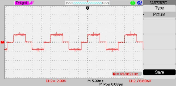
Digital signal controllers (DSC) is a single chip, embedded controller that integrates the control attributes of a MCU with computation and throughput capabilities of a DSP in a singe core . Line voltage means that it's running on the line voltage of the home without a transformer, which is 120 volts. During balanced condition there will be no current flowing through the neutral line and hence there is no use of the neutral terminal. But when there will be unbalanced current flowing in the three phase circuit, neutral is having a vital role.
Fig 5.a output of line voltage
Measure on any phase (S1 or S2 or S3) with respect to Neutral, it is called "Phase Voltage." It is and mediator between the three wires, producing the combinations of (S1, S2-S2, S3-S3, S1).
Fig 5.b output of phase voltage
A three phase transformer has three sets of primary and secondary windings. Depending upon how these sets of windings are interconnected, determines whether the connection is a star or delta configuration.
VI. CONCLUSION
The implementation of the proposed scheme on a digital signal processor (DSP) is formulated, where the runtime of the vector control algorithm is shorter. A TMS320F2812 DSP- based prototype is developed with the capability of compensating various disturbances occurring in the system and results as a feasible and effective controller. The digital signal controller comprises all the capabilities of the DSP processor into a small integrated chip likely dsPIC 33/30. The industrial applicable drives are said to be called either as constant speed drives (AC) or variable speed drives (DC). The induction motor is called as constant speed drive as the speed of the motor is constant throughout the function.
REFERENCES
[1] J.A.Santisban and R.M.Stephen, “vector control methods for induction machines: An overview,” IEEE Trans. Educ., vol.44, no.2, pp.170-175, May 2001.
[4] R.W.De. Doncker and D.W.Novothy,”The,” The universal field oriented controller,” in conf.Rec.IEEE-IAS Annu.Meet, 1988, pp.450-456.
[5] M.Depenbrock,”Direct self control (DSC) of inverter fed induction machine,”IEEE Trans, Power Electronic, vol.3, pp.420-429, 1988. [6] R. Stephan, “Field oriented and field acceleration control for induction motors. Is there a difference?” in Proc. IECON, 1991, pp. 567– 572.
[7] M. Barut, S. Bogosyan, and M. Gokasan, “Speed sensorless estimation for induction motors using extended Kalman filters,” IEEE Trans. Ind. Electron., vol. 54, no. 1, pp. 272–280, Feb. 2007.