Available online: https://edupediapublications.org/journals/index.php/IJR/ P a g e | 3443
Design and analysis of g+20 buildings using shear wall
GOLUSULA SURESH
Assistant professor, Avn institute of engineering & technology, Ibrahimpatnam (m), R.R district [email protected]
ANISETTI KRISHNA KANTH
Assistant professor, Avn institute of engineering & technology, Ibrahimpatnam (m), R.R district. [email protected]
SILIVERU NARESH
Assistant professor, Avn institute of engineering & technology, Ibrahimpatnam (m), R.R district [email protected]
Abstract: Study the behavior of structure when obtainingfloating columns, obtaining shear wall, and both shear walland floating columns structure with comparing the normalstructure. Also comparing the parameters like storeydisplacements, storey drift, storey shear, time period.Considering G+20 storey building, four models. First model will consider the normal building, second model will considerfloating columns structure, third model will consider shearwallstructure, fourth model will consider both shear walls and floating columns structure. The seismic analysis of G+20 storeystructure is analysed by both equivalent static and responsespectrum method. Using Indian Standard code IS 1893(Part-1) 2002 and ETABS-2016 software. Obtained storeydisplacements, storey shear, storey drift, time period forseismic zone V. Consider the both equivalent static methodand response spectrum method. 1.2(DL+LL+RSY) loadcombination is critical and increased displacements model IIis 6%, decreased 45% in model III, 40% in model IV. The storeydrift compared normal structure increased drifts in model IIis 9%, decreased 40% in model III, and 31% in model IV. Thestorey shear compared normal structure decreased shears inmodel II is 4.5%, increased 24% in model III, and 23% in
model IV. Comparing all four models the time period offloating column building model II is greater than all threebuilding. Model III is better performances lesser displacements,more strength comparing all models.
Key Words: Floating column, Shear wall, Storeydisplacements, Storey drift, Storey shear, Equivalentstatic method, Response spectrum method.
1. INTRODUCTION
Available online: https://edupediapublications.org/journals/index.php/IJR/ P a g e | 3444 represents a structurally efficient solution to stiffen abuilding structural system because the main function of ashear wall is to increase the rigidity for lateral loadresistance.In our country many urban multi story buildings first storeywill be open as an unavoidable future. This is being adoptedfor accommodate majorly vehicle parking, reception lobbies,or halls etc. in the first storey. During earthquake the totalseismic base shear of the building is dependent on its natural period, the seismic force distribution is dependent on thedistribution of stiffness and mass along the height. Thebehavior of a building during earthquakes depends criticallyon its overall shape, size and geometry, in addition to howthe earthquake forces are carried to the ground. Theearthquake forces developed at different floor levels in abuilding need to be brought down along the height to theground by the shortest path, any deviation or discontinuityin this load transfer path results in poor performance of thebuilding. Buildings with vertical setbacks like the hotelbuildings with a few storey wider than the rest cause asudden jump in earthquake forces at the level ofdiscontinuity. Buildings that have fewer columns or walls ina particular storey or with unusually tall storey tend todamage or collapse which is initiated in that storey.
LITERATURE REVIEW
IshaRohilla, S. M. Gupta, BabitaSaini. (2015) [1]
In this paper studied the seismic response of the multistory irregular building with floating column. The building model will be considered as G+5 and G+7 with zone II and zone V. To evaluate the results of the building as storey response, storey shear, storey displacements will be obtained by the using of ETABS software. The floating column should be avoided in high rise building in zone V. Storey displacements increases with increase in load on floating column. Storey shear will be decreases when presence of floating column because of reduction mass of column in structures. Increase the size of the beams and columns to improve the performance of building with floating column to reduce the storey displacements and storey drift.
KandukuriSunitha, Mr. Kirankumar Reddy. (2017) [2]
In this paper studied on the analysis of normal building with five storey, ten syorey, and fifteen storey. And different positions and different conditions like floating columns, shear wall, bracings are to taken as same models. Two methods to be considered for the analysis of structure as linear static method and time history method. Analysis done for using ETAB software compare the displacements, storey drift and the time history values of the different models. In static analysis concluded that the maximum displacements and storey drift values are increasing for floating column.by observing the drift ratio the deflection and storey drift will be drastically changed when the height of the building will be increased.
OBJECTIVES OF THE STUDY
Available online: https://edupediapublications.org/journals/index.php/IJR/ P a g e | 3445 2) Modeling the four different models as G+20 storeystructures as, Normal bared frame building, with shearwall structure, with floating column structure andcombination of floating column and shear wallstructures.
3) Seismic analysis is done by equivalent static methodand dynamic analysis by response spectrum methodwith seismic zone V
4) Obtaining the parameters storey displacements, storeyshear, storey drift, time period for modeled structures.
5) Comparing the results of normal building with shearwall building. 6) Comparing the results of normal building with floatingcolumn building.
7) Comparing the results of normal building withcombination of floating column building and shearwall building.
METHODOLOGY
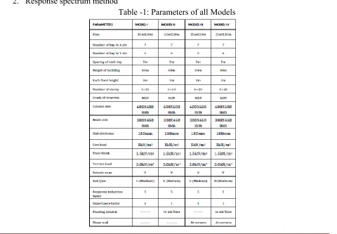
Consider the G+20 storey, four different structure andanalysing structures by using as per Indian standard code IS1893 (Part-1) 2002 and ETABS-2016 software. To determinethe parameters like storey displacements, storey shear,storey drift, time period, the following method will be
adopted for the analysis purpose. 1. Equivalent static method 2. Response spectrum method
Available online: https://edupediapublications.org/journals/index.php/IJR/ P a g e | 3446 Model I: This model or RC structure is consider as normal building or bared frame structure. Model II: This model consider floating column structure. (floating columns in ground floor) Model III: This model consider shear wall structure. (shear walls at all corners of the building) Model IV: Structure is consider both shear walls and floating columns structure.
Fig -1: Plan of Normal structure Model I
Fig -2: Elevation of Model I
Fig -3: Elevation of Model I
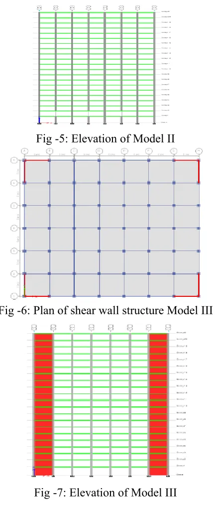
Available online: https://edupediapublications.org/journals/index.php/IJR/ P a g e | 3447 Fig -5: Elevation of Model II
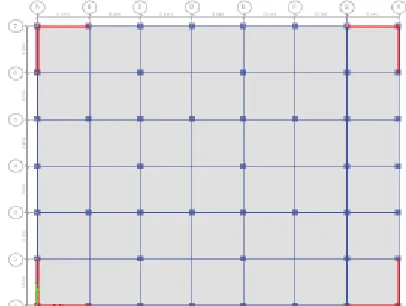
Fig -6: Plan of shear wall structure Model III
Available online: https://edupediapublications.org/journals/index.php/IJR/ P a g e | 3448 Fig -8: Plan of both shear walls and floating columns structure Model IV
Fig -9: Elevation of Model IV
Fig -10: Elevation of Model IV
Available online: https://edupediapublications.org/journals/index.php/IJR/ P a g e | 3449 Chart -1: Displacements v/s storey for 1.2(DL+LL+EQY) load combination.
Chart -2: Displacements v/s storey for 1.2(DL+LL+RSY) load combination.
Chart 1 represents the storey displacements v/s storey in Y direction, zone V for the combination of 1.2(DL+LL+EQY). Results will be critical and obtained from equivalent static method. Observing the results and chart comparing to normal building (model-I), the storey displacements is increased 4% in model II, decreased 24% in model III, decreased 21% in model IV.Chart 2 represents the storey displacements v/s storey in Y direction, zone V for the combination of 1.2(DL+LL+RSY). Results will be critical and obtained from response spectrum method. Observing the results and chart comparing to normal building (model-I), the storey displacements is increased 6% in model II, decreased 48% in model III, decreased 40% in model IV.
Available online: https://edupediapublications.org/journals/index.php/IJR/ P a g e | 3450 Chart -4: Drifts v/s storey for 1.2(DL+LL+RSY) load combination.
Chart 3 represents the storey drifts v/s storey in Y direction, zone V for the combination of 1.2(DL+LL+EQY). Results will be critical and obtained from equivalent static method. Observing the results and chart comparing to normal building (model-I), the storey drifts is increased 8% in model II, decreased 26% in model III, decreased 20% in model IV.
Chart 4 represents the storey drifts v/s storey in Y direction, zone V for the combination of 1.2(DL+LL+RSY). Results will be critical obtained from response spectrum method. Observing the results and chart comparing to normal building (model-I), the storey drifts is increased 9% in model II, decreased 40% in model III, and decreased 31% in model IV.
Available online: https://edupediapublications.org/journals/index.php/IJR/ P a g e | 3451 Chart -6: Storey shear v/s storey for 1.2(DL+LL+RSY) load combination.
Chart 5 represents the storey shears v/s storey in Y direction, zone V for the combination of 1.2(DL+LL+EQY). Results will be critical and obtained from equivalent static method. Observing the results and chart comparing to normal building (model-I), the storey shears is decreased 4% in model II, increased 24% in model III, increased 23% in model IV.
Chart 6 represents the storey shears v/s storey in Y direction, zone V for the combination of 1.2(DL+LL+RSY). Results will be critical and obtained from response spectrum method.
Observing the results and chart comparing to normal building (model-I), the storey shears is decreased 4.5% in model II, increased 24% in model III, and increased 23% in model IV.
Chart -7: Time period v/s first three modes
Chart 7 represents the time period v/s first three modes of the models. The time period is obtained from the modal participation factor. Comparing all four models the time period of floating column building model II is greater than all four buildings.
6. CONCLUSIONS
1) Seismic analysis of G+20 storey structure is done by both equivalent static and response spectrum method to obtained the parameters storey displacements, storey shear, storey drift, time period for seismic zone V.
Available online: https://edupediapublications.org/journals/index.php/IJR/ P a g e | 3452 3) Storey drift obtained from equivalent static method and response spectrum method, increased the storey drift 9% in model II, decreased 40% in model III, 31% in model IV.
4) Storey shear obtained from equivalent static method and response spectrum method, decreased the storey shear 4.5% in model II, increased 25% in model III, 24% in model IV. 5) Compared all four structures the time period of floating column building model II is greater than all four buildings.
6) Model III shear wall structure is better performances lesser displacements, more strength comparing all models.
REFERENCES
[1] IshaRohilla, S. M. Gupta, Babitasaini. “Seismic response of multi storey irregular building with floating column.” International Research Journal of Engineering and Technology Volume: 04 Issue 03 March - 2015. Page no 506-518.
[2] KandukuriSunitha, Mr. Kirankumar Reddy. “Seismic analysis of multistory building with floating column by using Tabs.” International Journal of Engineering Technology Science and Research Volume: 4 Issue 8 August -2017. Page no 933-943.
[3] P. P. Chandurkar, Dr. P. S. Pajgade. “Seismic analysis of RCC Building with and without shear wall.”International journal of modern engineering research Vol.3 Issue.3, May - June 2013. Page no 1805-1810.
[4] Sachin. P. Dyavappanavar, K. Manjunatha, Kavya N. “Seismic analysis of RC multistoried structures with shear walls at different locations.” International Research Journal of Engineering and Technology Volume: 02 Issue 06 August -2015. Page no 214-219.