Implementation of optimized Parallel-LC-Resonance Type Fault
Current Limiter
L.Sunitha1, M.Sai Kumar2 1
M.Tech student, PEES, S.R. Engineering College,India
2
Assistant Professor,EEE, S.R. Engineering College , India
Abstract:Fault current Limiter (FCL) supplies low rate solutions tosubstitute conventional defense devices. This protects other equipment onthe process from getting damaged by way of immoderate fault currents.FCLraised to becomeexcellent alternative to scale down rankings of circuit breakers and may limit theelectromagnetic stress in related equipments. In this paper a brand new parallel resonanceFault current Limiter (FCL) has been modified in a waythat may sustain the magnitude of fault present and manageit in a favored worth. The operation is based on making use ofparallel L&C resonance circuit with a resistor that reducestransient time and a pair of thyristors for controlling thevalue of fault current. Additionally, the proposed FCL doesnow not use a superconducting inductor which has highbuilding cost. Analytical evaluation for this structure ispresented in detail, and simulation outcome are acquired tovalidate the effectiveness of this structure.
The simulationresults are obtained utilizing
MATLAB/SIMULINK.
Keywords-Parallel-Resonance Type Fault Current
Limiter(FCL), Point Of Common Coupling (PCC), Power Quality (PQ), Semiconductor Switch.
I. INTRODUCTION
Power utilities spend millions on system up-gradationand to maintain new circuit breakers. Fault Current Limiter(FCL) is a low-cost solution which can protect the systemas well as, is financially beneficial. Fault Current Limiter(FCL) is the technological answer to the problem of higherlevel of short circuit current where system amplificationtakes place and replacement of whole protectionswitchgear is not achievable. FCL is the topic of activeresearch worldwide. There are different types of FCLs thatare being actively designed, some have been marketed butare either very expensive or have not achieved
thetechnical suitability yet. For hugely reliable power supply,fault current limiter (FCL) is becoming a vital part in themodern power system. The conventional technology usedat present to clear the fault is based on circuit breaker(C.B) with over current relay [1].The circuit breaker (C.B)which is rated for the full systems short circuit current islocated to ensure the adequate protection of the powersystem during permanent faults. The typical operationaltime delay of practical circuit breaker ranges from limitedcycles to several seconds. During this time, only thesystem impedance can limit the fault current. Currentlimiting device is required to be introduced into the powersystem for limiting the fault current before opening thecircuit breaker [2]. The implementation of FCLs in electricpower systems is not restricted to suppress the amplitudesof the short circuits; they are also utilized to variety ofperformances such as the power system transient stabilityenrichment, power
quality improvement, reliabilityimprovement,
increasing transfer capacity of systemequipment, and inrush current limitation in transformers[3][6]. An ideal FCL should have the followingcharacteristics [7]:
Zero resistance impedance at normal
operation;
No power loss in normal operation and
fault cases;
Large impedance in fault condition;
Quick appearance of impedance when fault
occurs;
Fast recovery after fault removed;
Reliable current limitation at defined fault
current;
Good reliability;
In [8] and [9] a new parallel resonance type FCL hasbeen introduced. Due to its novel topology it can put upwith magnitude of fault in a constant value by insertinghigh impedance in fault time. Fault current limiters havemany different topologies comprising superconductingFCLs, resonance-type FCLs and solid-state FCLs.Superconducting FCLs bounds the fault current by using asuperconducting coil. In the normal system operatingcondition, this coil has little resistance. When a shortcircuit fault occurs, the resistance of this coil will risedrastically. Thus the current will be limited [10].Resonance types FCLs limit the current by the resonancebetween their capacitor and inductor during the fault.
II. RELATED WORK
In this paper, a new structure for a parallel-LCresonance type FCL is introduced. The proposed FCL uses aresistor in series with a capacitor, and therefore, it cansimulate load impedance during fault. By this way, it canlimit the fault current level near to pre-fault condition. Fromthe power quality point of view, by equating fault currentand before-fault line current, the voltage of the point ofcommon coupling (PCC) will not experience considerablechange during fault condition, and power quality willimprove. In comparison with the previously introducedresonance-type FCLs, this FCL does not use asuperconducting inductor in the resonant circuit, and as aresult, it is simpler to manufacture and has lower cost.Analysis and design considerations for this FCL arepresented, and matrix laboratory (MATLAB) software is used to solve the resulted formulas. The circuit operationin the normal and fault conditions is simulated by usingMatlab/Simulink software.
III. RESONANT TYPE FCL
Proposed topology of fault current limiter is shown in fig.1. This circuit consists of a two resonant branch, twothyristors T1and T2and a resistance.During normal process of circuit, the thyristors is offand the resonant branches are short circuit (C1and L1, C2and L2). The relationship between (C1, C2) and (L1, L2) areshown in equations (1), (2) as follow:
= ⟹ = ……….(1)
= ⟹ = ………. (2)
Fig. 1. Circuit diagram of resonant type FCL.
Therefore, there is not any voltage drop on FCL. In thisway, in normal system operation case, the FCL will nothave almost any effect on load operation. After a shorttime of fault happening, when line current reaches to desirevalue for control circuit, the control circuit will trigger thethyristors T1 and T2 in
positive and negative alternancerespectively.
Therefore, the resistance of FCL conductsfault current and limits it.
Fig.2. Circuit Diagram of resonant type FCL when fault occur without using resistance.
So, in this case FCL have equivalent impedance that itcan limit the fault current. The magnitude of correspondingimpedance and also the magnitude of fault current dependon the resistance magnitude and trigger phase angle ofthyristors. Without using resistance when thyristorsactivated the equivalent impedance will be infinite. Fig.2.shows the FCL mode in fault time without using resistance.Equations (3), (4) show the FCL equivalent impedance.
= ⟹ = ⟹ = ∞ ………(4)
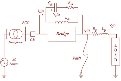
Fig.3. shows the single-phase circuit topology of the proposed FCL. It is essential to use a similar circuit foreach phase in a three-phase distribution system. Thisstructure is composed of two main parts which are asfollows:
Bridge Part: This part consists of a rectifier bridgecontaining D1- D4 diodes, a small dc-limiting reactor (Ldc),a self-turnoff semiconductor switch (such as a gate turnoffthyristor and an insulated-gate bipolar transistor) and itssnubber circuit, and a freewheeling diode (Df).
Resonance Part: This part contains a parallel LCresonance circuit (Lsh and Csh) (its resonant frequency isequal to power system frequency) and a resistor Rsh inseries with the capacitor. The bridge part of the proposedFCL functions as a high-speed switch that changes thefault current path to the resonance part when the faultoccurs. Observably, it is possible to substitute this partwith an anti-parallel
connection of two self-turnoffsemiconductor
switches. Using a diode rectifier bridge hastwo advantages compared to two anti-parallel switches as follows:
This structure practices only one
controllable semiconductor switch which operates in the dc sideinstead of two switches that operate in the ac side. The control circuit is simpler because of no need forON/OFF switching in the normal operation case.
It is possible to use a small reactor in series with the semiconductor switch at the dc side. This reactor plays two as follows:
It is snubber for a semiconductor switch.
It is as a current limiter at first moments of
fault occurrence. However, placing the dc reactor inside the bridge makes the voltage drop on it because of dc current ripple.
However, the current ripple is low, and consequently, the voltage drop caused by it is not significant in comparison with the feeder’s voltage. Current ripple and voltage drop equations are studied entirely in
[15]. It is important to note that high-rating semiconductor switches are commercially available with current rating up to 24kA and voltage rating up to 4 kV. Also, it is possible to use more or less series and/or parallel self-turnoff switches considering high current and voltage levels. The semiconductor switch needs a suitable snubber circuit for its protection, which is not shown in Fig. 3 for simplicity.
Fig.3. Single-phase power circuit topology of the proposed parallelresonance-type FCL
Also, high-rating semiconductor switches, their protection procedure, and minimization of their power losses are discussed. From the power loss point of view, in the normal condition, the proposed FCL has the losses on the rectifier bridge diodes, the semiconductor switch, and the small resistance of the dc reactor. Each diode of the rectifier bridge is ON in half a cycle, while the semiconductor switch is always ON. Therefore, the power losses of this FCL in the normal operation can be calculated as
P = P + P + P = R I + 4V I +
V I ………..(5)
I -- dc side current which is equal to the peak of the
line currentI
R ---Resistance of the dc reactor;
V −Forward voltage drop on each diode
V − Forward voltage drop on the semiconductor
switch;
I − average current of the diodes in each style that
Considering (1) and the small value of the dc reactor inthis structure, the total power losses of the proposedstructure develop a very small percentage of the feeder’stransmitted power.
Fig. 4. Control circuit of the proposed FCL.
Fig.4. shows the control circuit of the proposed FCL. In the normal operation of the power system,
thesemiconductor switch is ON. Therefore, Ldcis
charged tothe peak of the line current and behaves as a short circuit.Using the semiconductor devices (the diodes andsemiconductor switch) and the small dc reactor causes aminor voltage drop on the FCL. When a fault occurs, thedc current becomes greater than the maximum permissiblecurrent I0, and the control circuit detects it and turns thesemiconductor switch off. Therefore, the bridge retreatsfrom utility.
At this moment, the freewheeling diode Dfturns ON
and provides free path for discharging the dcreactor. When the bridge turns OFF, the fault currentpasses through the parallel resonance part of the FCL.Accordingly, large impedance enters to the circuit andprevents the fault current from growing. In the faultcondition, the parallel LC circuit starts to resonate. In thiscase, because of resonance, the line current oscillates withlarge magnitude. These oscillations may lead to damagingsystem equipment or putting them in stress. Though, byplacing a
resistor (Rsh) in series with the capacitor,
currenttransients damp quickly. In addition, by using
Rsh, thevoltage drop on Rsh causes that the voltage
across thecapacitor is decreased during fault.
When the fault disappeared, while the semiconductor switch is OFF, the parallel part of the FCL will beconnected in series with load impedance. Hence, the linecurrent will be reduced instantaneously. To
detect thisinstantaneous reduction of the line current,
iL is comparedwith If that can be calculated from
=| |
| | …………(6)
Where Zeq is the equivalent impedance of the
resonancepart. When the difference of iL and If becomes greater thank as the fault removal sign, the control circuit turns thesemiconductor switch ON. Therefore, the power systemreturns to the normal state. The value of k can becalculated from
=| |
| | −
| |
| , | ………(7)
Where ZL,min is the minimum impedance of the load
on theprotected feeder. As pointed, some of previously proposedFCL structures have ac power losses at the resonant circuitin the normal condition, because of placing a large inductorin the line current path. However, the proposed structure inthis paper has very low losses in the normal condition,because the inductor is bypassed by the bridge part. Also,by choosing proper values for the resonant circuit, the proposed FCL limits the fault current in a way that thepower system is not affected by the fault. In such condition, there will not be any considerable voltage sag onthe PCC voltage as shown in Fig.5.
Fig.5. Single-Line Diagram of the Power System.
IV. CONCLUSION
presented. Theanalytical analysis and design deliberations for thisstructure have been presented. Maintaining DG’s currentlevel to its pre-fault one during a short circuit condition,the parallel-resonance-type FCL can restore the re-closerto fuse coordination, which was lost because of theoverview of DG’s. Whereas the resonance type FCLcan be designed so as to restore the coordination, but itwill decrease DG’s current during normal condition and thusits application might be undesirable.
REFERENCES
[1] M. Jafari, S. B. Naderi, M. TarafdarHagh, M.Abapour, and S. H. Hosseini, “Voltage sag compensationof point of common coupling (PCC) using fault currentlimiter,” IEEE Trans. Power Del., vol. 26, no. 4, pp. 2638–2646, ct. 2011.
[2] S. P. Valsan and K. S. Swarup, “High-speed faultclassification in power lines: Theory and FPGA-basedimplementation,” IEEE Trans. Ind. Electron., vol. 56, no.5, pp. 1793–1800, May 2009.
[3] P. Rodriguez, A. V. Timbus, R. Teodorescu, M.Liserre, and F. Blaabjerg, “Flexible active power control ofdistributed power generation systems during grid faults,”IEEE Trans. Ind. Electron., vol. 54, no. 5, pp. 2583– 2592,Oct. 2007.
[4] M. F. Firuzabad, F. Aminifar, and I. Rahmati,“Reliability study of HV substations equipped with thefault current limiter,” IEEE Trans. Power Del., vol. 27, no.2, pp. 610–617, Apr. 2012.
[5] A. Y. Wu and Y. Yin, “Fault-current limiterapplications in medium- and high-voltage powerdistribution systems,” IEEE Trans. Ind. Electron., vol. 34,no. 1, pp. 236–242, Jan./Feb. 1998.
[6] M. TarafdarHagh and M. Abapour,
“Nonsuperconducting fault currentlimiters,” Euro. Trans. Power Electron., vol. 19, no. 5, pp.669–682, Jul. 2009.
[7] M. TarafdarHagh, M. Jafari, and S. B.
Naderi,“Transient stability improvement using
nonsuperconducting fault current limiter,” in Proc.
IEEE 1stPower Electron. Drive Syst. Technol. Conf.,
Feb. 2010, pp.367–370.
[8] S. H. Hosseini, M. TarafdarHagh, M. Jafari, S. B.Naderi, and S. Gassemzadeh, “Power quality improvementusing a new structure offault current limiter,” in Proc. IEEE ECTI_CON,May2010, pp. 641–645.
[9] A. Gyore, S. Semperger, L. Farkas, and I. Vajda,“Improvement of functionality and reliability by inductiveHTS fault current limiter units,” IEEE Trans. Appl.Supercond., vol. 15, no. 2, pp. 2086– 2089, Jun. 2005.
[10] Y.-H. Chen, C.-Y.Lin,J.-M. Chen, and P.-T. Cheng,“An inrush mitigation technique of load transformers forthe series voltage sag compensator,” IEEE Trans. PowerElectron., vol. 25, no. 8, pp. 2211–2221, Aug. 2010.
[11] M. Tsuda, Y. Mitani, K. Tsuji, and K.
Kakihana,''Application of resistor based
superconducting faultcurrent limiter to enhancement of power system Transient stability'', IEEE Trans. Appl. Supercond., vol.11, no. 1, pt. 2, pp. 2122–2125, Mar, 2001.
[12] M. T. Hagh and M. Abapour,
''Nonsuperconductingfault current limiters'', Eur. Trans. Elect. Power(ETEP), Published Online: Mar. 27, 2008.
[13] S.-H. Lim, H.-S.Choi, D.-C.Chung, Y.-H.Jeong, Y.-H. Han, T.-H. Sung, and B.-S. Han, “Fault current limitingcharacteristics of resistive type SFCL using a transformer,”IEEE Trans. Appl. Supercond., vol. 15, no. 2, pp. 2055–2058, Jun. 2005.
[14] B. C. Sung, D. K. Park, J. W. Park, and T. K. Ko,“Study on a series resistive SFCL to improve powersystem transient stability: Modeling, simulation andexperimental verification,” IEEE Trans. Ind. Electron., vol.56, no. 7, pp. 2412–2419, Jul. 2009.
[15] M. Abapour and M. TarafdarHagh,
“Nonsuperconducting fault current limiter with controlling themagnitudes of fault currents,” IEEE Trans. PowerElectron., vol. 24, no. 3, pp. 613–619, Mar. 2009.
L.Sunitha pursing M.Tech in PEES from Sr Engineering College,Warangal,Telangana,India.
M.Sai Kumar working as Assistant Professor,