An Effective Solution to Minimize The Dc Component In
Grid Connected Pv Inverters
A. Kusumanjali
1Dr.Samalla Krishna
2Mr.S.Srikanth
31
M. Tech Student Deptt of of Electrical & Electronics Engg. Tudi Ram Reddy Institute of Technology&Sciences, Hydearabad. [email protected]
2
Professors, & Principal. Tudi Ram Reddy Institute of Technology&Sciences, Hydearabad. [email protected]
3
Assistant Professor, Department of Electrical & Electronics Engg. Tudi Ram Reddy Institute of Technology & Sciences, Hydearabad. [email protected]
ABSTRACT
The main aim of project is dc component is a
special issue in transformer less grid-connected
photovoltaic (PV) inverter systems and may
causeproblems regarding system operation and
safety. This paper has proposed an effective solution to minimize the dc component in three-phase ac currents and developed a
software-basedapproach to mimic the blocking capacitors
used for the dc component minimization, the so-called virtual capacitor.. A proportional integral-resonant controller is further designed to
regulate the dcand line-frequency component in
the current loop to provide precise control of the dc current. The proposed method has been validated on a 10-kVA experimental prototype,
where the dc current has been effectively
attenuated to be within 0.5% of the rated current. The total harmonic distortion and the
second-order harmonic have also been reduced as well
as the dc-link voltage ripple. Grid connected photovoltaic (PV) systems often include a line transformer between the power converter and the grid. The transformer guarantees galvanic isolation between the grid and the PV systems, thus fulfilling safety standards. Furthermore, it ensures that no direct current (dc) is injected to the grid . However, the low-frequency (50 or 60 Hz) transformer is bulky, heavy, and expensive
and its power loss brings down the overall system efficiency.
Index terms: Grid connected PV inverter, PIR controller, virtual capacitor, harmonics
I.INTRODUCTION
There are several issues associated with transformerless structures, such as dc component in the inverter output (grid) current, ground leakage current (due to common-mode voltage and parasitic capacitance), and the
voltage-level mismatch between thesolar panel
(inverter) and grid. Among them, the dc component can affect the normal system
operation and cause safety concerns. Standards
have therefore been established in many countries to limit the level of the dc component,
for example, below 0.5% of the rated output
current (e.g., IEEE Standard 1547-2003).
Therefore, this paper will investigate effective solutions to minimize the dc component in a PV
system. The dc component can have negative
impacts on the power system in the following
ways: 1) The dc component can affect the
operating point of thetransformers in the power
system. The transformer cores are driven into
unidirectional saturation with consequent larger
increased hysteresis and eddy current losses and
noise. 2) The dc component can circulate
between inverter phase legs as well as among
inverters in a paralleled configuration. The dc
component circulation affects the even current
and loss distribution among paralleled inverters. 3) The dc component injected to the grid can affect the normal operation of the loads connected to the grid, for example, causing
torque ripple and extra loss in ac motors.4) The
corrosion of grounding wire in substations is
intensified due to the dc component. There are
several sources leading to the dc components in grid-connected inverters:
1) asymmetry in the switching behavior of power semiconductor devices,
2) imparity in gate drivercircuits,
3) device turn-on and turn-off delays,
4) nonidentical device voltage drops (on-state resistance, saturation voltage,etc.), and
5) sampling biases from the ac current and ac
voltagesensors, etc.
Minimization of the dc component in
transformerless PV inverters has been
extensively investigated in literatures. Several solutions have been developed which can be grouped
into two categories: passive methods and active
methods. For example, coupling transformers
and blocking capacitors are inserted on the
inverter ac side to minimize the dc component. The main disadvantage of this kind of passive
methods is the increased cost, weight, and
physical size of the system as well as extra
configurations, which are not extendable to other inverter topologies. Regarding active methods, auto calibrating techniques for dc-link sensors in two-level and three-level single-phase inverters were proposed which are effective to minimize the dc component caused by sampling biases of the ac current sensors. However, these methods are not suitable for the dc component caused by other sources, e.g., asymmetry in switching behavior and an extra dc-link current sensor is required. The authors use different methods to extract the dc component from the output current, and add feedback compensation to minimize it, which are only used in single-phase systems. To the authors’ knowledge, at the time of writing, only the technique in is for three-phase systems, which detects and uses the line-frequency voltage ripple on the dc-link to build an indirect feedback loop to compensate the dc component of the output current. However, since the dc components are not measured and feedback directly, the method cannot guarantee that the dc component in each phase is minimized effectively.
II. OPERATION OF PROPOSED SYSTEM
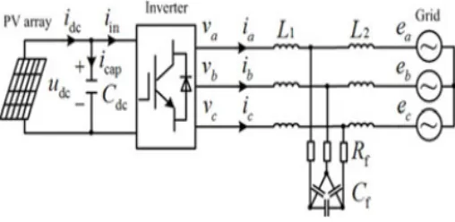
A typical three-phase transformerless PV inverter system is shown in Fig. The PV array is connected to the grid via a threephase
voltage-source two-level inverter and an LCL filter. The
Fig. 1. Transformerless three-phase PV inverter system.
In order to analyze the impact of dc components on the threephase PV systems, the dc components have been added in the system model in addition to the line (fundamental)-frequency components. If other harmonics are neglected and only the dc and line-frequency components are concerned, F can be defined as an electrical variable (e.g., for ac-side voltage and current) and is
expressed as in (1) in each coordinate (three-phase stationary (abc), two-phase stationary (αβ), and
two-phase rotational (dq))
where the subscript 0 denotes the dc component and the subscript 1 denotes the line-frequency component. Note that the zero component in conventional coordinate transformation is
not taken into account due to the three-wire system. If there are dc components in the abc coordinate, they
will also exist in the form of dc or line-frequency components in αβ and dq
coordinates, respectively. In a three-phase three-wire system, there is no current flowing through the neutral point and hence
With (1) and (2), the coordinate transformations of the dc components from abc coordinate to αβ
where θ is the angle between the dq coordinate and abc coordinate, for example, the grid angle in
a grid-voltage oriented vector control. As seen in (3) and (4), by the coordinate transformation, Fa0, Fb0,
and Fc0 (dc components) in the stationary abc frame can be transformed into Fα0 and Fβ0 in the stationary αβ frame and then Fd1 and Fq1 (line-frequency) in dq frame. Therefore, the voltage and current in the control loop of each frame will contain both dc and line-frequency components. The synthesized vector F of dc components can be decomposed in the frames shown in Fig, where F is a
stationary vector. Since the dq frame rotates anticlockwise, the dc component in the synchronous dq
frame appears in the form of a negative-sequence line-frequency component. According to the
instantaneous power theory [26], [27], the system active power pac and reactive power qac can be
expressed in (5) and (6) in the dq frame, where the mark “·” and the mark “×” are the inner and outer product of vectors, respectively
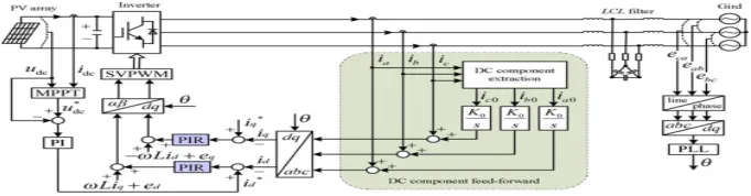
III.DC COMPONENT MINIMIZATION STRATEGY BASED ON DC COMPONENT FEED-FORWARD AND PIR CONTROLLER
In PV inverters, the Hall-effect current sensors are widely used to measure the ac-side currents (including both ac and dc components) due to their smaller size, isolated output, and wide bandwidth (e.g., from dc to several hundred kilohertz). In this paper, an integral method based on the sliding window iteration algorithm is used to accurately extract the dc component from the ac-side currents. Taking the ac-side Phase A current ia, for example, ia can be expressed as in (18) if considering both the dc component and other ac components of different frequencies (e.g., harmonics)
III.SIMULATION RESULTS
Fig 3. MATLAB/SIMULATION Circuit diagram of proposed system
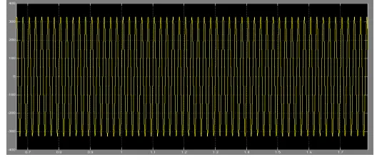
Fig 4. Three-phase grid-side currents in the grid-connected PV inverters
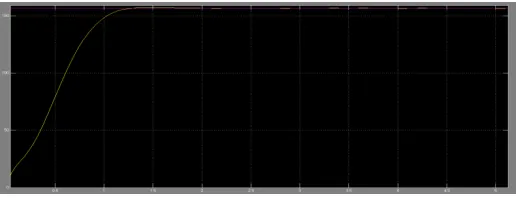
Fig 6. DC link voltage simulation and theretical
IV.CONCLUSION
The dc component can introduce line-frequency power ripple in the system and further cause dc-link voltage ripple and second-order harmonics in the ac currents. A softwarebased “virtual capacitor” approach has been implemented to minimize the dc component via a feed-forward of the dc component. The dc component can be accurately obtained using the sliding window iteration and double time integral even under frequency variation and harmonic conditions. A PIR controller has been designed to enable
the precise regulation of both the dc and line-frequency components in the d-q frame. Experimental
results have validated the proposed method, where the dc component has been reduced below 0.5% and the dc-link voltage ripple has been attenuated as well. The proposed method can be well adopted in the existing PV systems for dc component minimization by adding software programs for dc-component extraction, dc-component feedforward term as well as the resonant controller in the current control loops.
REFERENCES
[1] R. Gonzalez, E. Gubia, J. Lopez, and L. Marroyo, “Transformerless singlephase multilevel-based photovoltaic inverter,” IEEE Trans. Ind. Electron., vol. 55, no. 7, pp. 2694– 2702, Jul. 2008.
[2] S. B. Kjaer, J. K. Pedersen, and F. Blaabjerg, “A review of singlephase grid-connected
inverters for photovoltaic modules,” IEEE Trans. Ind. Appl., vol. 41, no. 5, pp. 1292–1306, Sep./Oct. 2005.
[3] E. Koutroulis and F. Blaabjerg, “Design optimization of transformerless grid-connected PV inverters including reliability,” IEEE Trans. Power Electron., vol. 28, no. 1, pp. 325–335, Jan. 2013.
[5] S. V. Araujo, P. Zacharias, and R. Mallwitz, “Highly efficient single-phase transformerless inverters for grid-connected photovoltaic systems,” IEEE Trans. Ind. Electron., vol. 57, no. 9, pp. 3188–3128, Sep. 2010.
[6] O. Lopez, F. D. Freijedo, A. G. Yepes, P. Fernandez-Comesaa, J. Malvar, R. Teodorescu, and J. Doval-Gandoy, “Eliminating ground current in a transformerless photovoltaic
application,” IEEE Trans. Energy Convers., vol. 25, no. 1, pp. 140–147, Mar. 2010.
[9] W. Li, L. Liu, T. Zheng, G. Huang, and S. Hui, “Research on effects of transformer DC Bias on negative sequence protection,” in Proc. Int. Conf. Adv. Power Syst. Automat. Protection, Beijing, China, Oct. 2011, pp. 1458–1463.
[10] A. Ahfock and A. J. Hewitt, “DC magnetisation of transformers,” IEE Proc.-Electr Power Appl., vol. 153, no. 4, pp. 601–607, Jul. 2006.
[11] M. A. S. Masoum and P. S. Moses, “Impact of balanced and unbalanced direct current bias on harmonic distortion generated by asymmetric threephase three-leg transformers,” IET Electr. Power Appl., vol. 4, no. 7, pp. 507–515, Jul. 2010.
[12] F. Berba, D. Atkinson, and M. Armstrong, “A review of minimization of output DC current component methods in single-phase grid-connected inverters PV applications,” in Proc. 2nd Int. Symp. Environ. Friendly Energies Appl., Tyne, U.K., Jun. 2012, pp. 296–301.
[13] M. Armstrong, D. J. Atkinson, C. M. Johnson, and T. D. Abeyasekera, “Auto-calibrating DC link current sensing technique for transformerless, grid connected, H-bridge inverter systems,” IEEE Trans. Power Electron., vol. 21, no. 5, pp. 1385–1393, Sep. 2006.
[14] F. Berba, D. Atkinson, and M. Armstrong, “Minimization of DC current component in
transformerless Grid-connected PV inverter application,” in Proc. 10th Int. Conf. Environ.Elect. Eng., Rome, Italy, May 2011, pp. 1–4.
[15] Y. Shi, B. Liu, and S. Duan, “Eliminating DC current injection in currenttransformer-sensed STATCOMs,” IEEE Trans. Power Electron., vol. 28, no. 8, pp. 3760–3767, Aug. 2013.
[16] G. Buticchi, E. Lorenzani, and A. Fratta, “A new proposal to eliminate the DC current component at the point of common coupling for grid connected systems,” in Proc. IEEE 36th Ann. Conf. Ind. Electron. Soc., Glendale, USA, Nov. 2010, pp. 3244–3249.
[17] T.-F. Wu, H.-S. Nien, H.-M. Hsieh, and C.-L. Shen, “PV power injection and active power filtering with amplitude-clamping and amplitudescaling algorithms,” IEEE Trans. Ind. Appl., vol. 43, no. 3, pp. 731–741, May/Jun. 2007.
[18] W. M. Blewitt, D. J. Atkinson, J. Kelly, and R. A. Lakin, “Approach to low-cost prevention of DC injection in transformerless grid connected inverters,” IET Power Electron., vol. 3, no. 1, pp. 111–119, Jan. 2010.
[19] R. Sharma, “Removal of DC offset current from transformerless PV inverters connected to utility,” in Proc. 40th Int. Universities Power Eng. Conf., Cork, Ireland, Sep. 2005, pp. 1230–1234.
[20] L. Bowtell and A. Ahfock, “Direct current offset controller for transformerless single-phase
AUTHOR’S PROFILE
DR. SAMALLA KRISHNA so far has successfully guided many post graduate students in the fields of Signal and Image Processing, Neural Networks and Pattern Recognition while several other students are being supervised by him in a wide variety of other fields like DSP, Medical Image Processing and Object Recognition in addition to this he supervised many electrical and other disciplinary engineering students .He served as an academic supervisor to more than 300 Bachelor Degree dissertations towards the award of Undergraduate Degree ,and He has published more than 35 research papers in reputed International Journals. He shared his research experience more than many podiums like conferences, workshops, seminars and symposia. And currently he is working as a professor in TUDI Group of institutions, Hyderabad. He has 12 years of experience in the teaching and research field. His many research articles are cited by scholars and research institutions.