Design of Panoramic Mosaic Camera Based on
FPGA Using Optimal Mosaic Algorithm
Sen Ma1, 2, Yuanyuan Shang1, 2, Weigong Zhang1, 2, Yong Guan1, 2, Qian Song3, Dawei Xu1, 2 1
College of Information Engineering, Capital Normal University, Beijing, China 2
Beijing Engineering Research Center of High Reliable Embedded System, Capital Normal University 3
National Astronomical Observatories, Chinese Academy of Sciences Email: [email protected]
Abstract—It was the panoramic technology that extensively
used in the scopes of Video Compression, Virtual Reality, Pathology of Medical Science, Teleconference System and so on. Panoramic mosaic perspective, taking both full view images of a sight of view, is a critical figure of merit for a panoramic system. This paper introduces the design of a panoramic mosaic camera, which is used in the special circumstances that required both with view and ambulant ability. The camera achieves panoramic perspective by analyzing optical structure and using multiple image sensors. A mosaic algorithm to rapidly locate the coordinate of overlapped area and to obtain real-time performance in embedded system is analyzed and optimized. In addition, the Ethernet interface, to send the panoramic view to the remote terminal, is also discussed. Finally we present the evaluation results, showing that this camera can satisfy the requirement of panoramic systems.
Index Terms—Panoramic Mosaic Camera, FPGA, Image
Mosaic
I. INTRODUCTION
The advancement of image sensor, the resolution of image is become bigger. With the development of image mosaic technology, the panoramic perspective is demand more often. Albeit the similar consequence is obtainable through the broad angle lens, the distortion cannot avert at the verge of the optical apparatus. Hence, the panoramic mosaic technology emerged to vanquish the flaws [1], [2].
In the present era, the contemporaneous prospective in panoramic mosaic is seeking the same segment in the coterminous image by some algorithm and defining the coordinate for image fusion. Unfortunately, to obtain panoramic perspective filed of scene, it is required to develop a multi camera system with human operations which brings more expenditure. Due to the complicated algorithm of image capture, this kind of panoramic system is usually demands excess resources both in hardware and software, which shows the limitation of real-time performance and portable ability [3], [4].
Therefore, this paper mainly discusses the design of a panoramic mosaic camera to automatically obtain panoramic perspective through two complementary metal-oxide-semiconductor (CMOS) sensor and an optimal mosaic algorithm which have real-time
performance based on Field Programmable Gate Array (FPGA) embedded system.
First of all, in the Imaging part, the article demonstrated the optical structure of the entire system and achieved the drive of CMOS image sensor THDB-D5Ms. Secondly, the mosaic algorithm and the methodology are detailed in the image mosaic part. The article optimized the correlation algorithm and simulated the method in the MATLAB. It also elaborated the fulfillment of the method in FPGA embedded system, with contained four kernel modules: Fast Fourier Transformation (FFT) module, raw format image convert to bitmap module, bitmap convert to YUV module and SDRAM module. After that, the YVU convert to Bitmap module and Video Graphic Array display module were presented in Image Display part. After that, both the Ethernet interface which included manually program net frame structure and design of remote client application were presented. Furthermore, the whole system was fulfilled in the DE2-70 embedded framework and evaluation test were carried out. From the results of the experimental control, this camera satisfies the requirements of the panoramic situations.
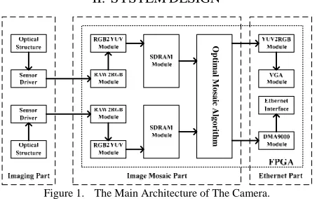
II. SYSTEMDESIGN
The Panoramic mosaic camera is composed of three components: the imaging CMOS sensor part, the image mosaic part and the Ethernet interface part. The CMOS sensor includes two THDB-D5Ms, which are five mega pixel digital CMOS sensor. Each sensor contains a power voltage circuit, a low noise amplifier and a clock driver circuit [5], [6]. The image mosaic part composed with raw to bitmap module which is charge of conversion for the raw image obtained from CMOS sensor, bitmap to
O
p
ti
m
a
l M
o
sa
ic
A
lg
o
ri
thm
A. Optical Structure of Panoramic Perspective
To obtain panoramic perspective of scene, panoramic mosaic camera contains two optical acquisition systems combined with two CMOS sensors. The optical structure of panoramic perspective is presented in Fig. 2. The filed of view of each optical subsystem is
θ
, and the overlapped area isω
. The optical axes of subsystem areL
1andL
2, which are parallel to the center lineL
.The distance between
L
1andL
2ish
. The images of regionω
received by two image sensors are same. The key function for this camera is automatically detect the coordinate of the overlapped area and use algorithm to fusion the two images into one panoramic image.B. CMOS Sensor
THDB-D5M CMOS sensor from Terasic Corporation is used in this panoramic mosaic camera. It contains two different operation modes: full frame mode and frame transfer mode. The array size of the THDBD5M is 2592×1944 [7], [8]. There is only one readout register in the sensor, located at the top of the image area. The register is driven independently by two phase clocks. This CMOS sensor has high frame rate and low dark current. Moreover, to meet the demand of taking frames, the snapshot mode is provided. Both the column and row skip modes of the CMOS sensor reduce image size without reducing field of view. The features of THDB-D5M are controlled by customized Hardware Description Language (HDL), such as gain, frame rate, frame size, exposure [9], [10].
The resolution of the output image is the full width and height of the field of view in the default settings. There are two methods to reduce the output resolution: Skipping and Binning. Row and column skip modes use subsampling to reduce the output resolution without reducing field of view [11], [12]. The sensor also has row and column binning modes, which can reduce the impact
IV.IMAGEMOSAIC
A. Optimal Mosaic Algorithm
The basic principle of mosaic methodology is phase correlation algorithm which is a nonlinear method based on Fast Fourier Transform. This algorithm only relate with the information of cross-power spectrum. As a result, it is undependable with the specific content of image [15], [16]. Beside, phase correlation algorithm does not rely on the value of gray image. So as to, it is very robust to obstruction and has advantages to porting in embedded system.
If we wish to match images
f x y
1( , )
andf x y
2( , )
, and only translational radiation exist betweenf
1andf
2. It means1
( , )
2(
0,
0)
f x y
=
f x
−
x y
−
y
(1)Substituting to FFT features, the result of conversion is
1 0 2 0
( )
1
(
1,
2)
2(
1,
2)
j x y
F
ω ω
=
e
− ω +ωF
ω ω
(2)In this equation,
F
1(
ω ω
1,
2)
andF
2(
ω ω
1,
2)
is corresponding FFT result ofF
1andF
2. The cross-power spectrum is1 0 2 0 *
( )
1 1 2 2 1 2
*
1 1 2 2 1 2
(
,
)
(
,
)
(
,
)
(
,
)
j x y
F
F
e
F
F
ω ωω ω
ω ω
ω ω
ω ω
− +=
(3)After have the inverse FFT, a correlation function can be acquired ) ( 1 2 1 * 2 2 1 1 2 1 * 2 2 1 1
1 10 2 0
)
,
(
)
,
(
)
,
(
)
,
(
j x ye
F
F
F
F
F
F
d
ω ωω
ω
ω
ω
ω
ω
ω
ω
− − + −=
⎥
⎥
⎦
⎤
⎢
⎢
⎣
⎡
=
(4) ω θ L 1 L 2 L h θFigure 2. Optical Structure of Panoramic Perspective.
2X Skip Mode 2X Bin & Skip Mode
In Equation (4), the equation
d
is a two-dimensionalδ
function. The overlapped area corresponds to coordinate( ,
x y
0 0)
can be obtained through the max value ofδ [17].Although the performance of phase correlation algorithm is verified through the simulation test in Matlab, the FFT for the whole image which more than 800×480 pixels is too complicated to achieve in embedded system. Hence, we optimize the algorithm by select special region pixels. To detect the special region, five hundreds pair of test were set and the consequence is shown in Fig. 4. Since the position of two image sensor is settled, the coordinate of the overlap region is aggregate between 190 to 197 from x-coordinate and 0 to 7 from y-coordinate. In this case, the special region contains 64 pixels and the FFT for special region can fulfill in FPGA embedded system.
B. RAW To RGB Module
To acquire more real information of the view, the best solution is use three CMOS chips to obtain the red, green and blue independently. Then combines the three colors
information to get the final details about the view, but most digital cameras in the market are use only one CMOS chip to obtain the view information for the perspective of cost. The traditional way is using Bayer
filter mosaic which is a color filter array (CFA) for arranging RGB color filters on a square grid of photo sensors [18]. This unprocessed image form named raw format and therefore is not ready to be used with a bitmap graphics editor or printed.
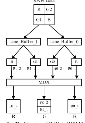
The raw format output of Bayer-filter cameras is referred to as a Bayer pattern image. Since each pixel is filtered to record only one of three colors, the data from each pixel cannot fully determine its own color [19]. The structure of RAW to RGB Module is presented in Fig. 5. The data of RAW file firstly passes the Line_Buffer_0
and Line_Buffer_1 to save first two rows data in these buffers. Then set the B0_1 with first pixel of row one, as shown in B, and set the B0_2 with first pixel of row two, as shown in G2. The same as B1_1 and B1_2, they are set by the second pixel of first two rows, as shown in G2 and
R. After that, all of B0_1, B0_2, B1_1 and B1_2 send to
MUX logical to gain the RGB data through maintain the value of B0_1 and B1_2 as the value of blue color and red color, and get the sum of B0_2 and B1_1, two values of green, as the value of green color.
C. RGB To YUV Module
YUV is a family of color spaces used as a part of the Color image pipeline in video and digital photography systems [20]. Y is the luminance component and U and V are the blue difference and red-difference chromatic purity components. YUV is not an absolute color space. It is a way of encoding RGB information. The actual color display depends on the actual RGB colorants used to display the signal. Therefore a value expressed as YUV is only predictable if standard RGB colorants are used [21].
For efficiently compress the color information when the high performance of Ethernet transportation is acquired, convert color information from RGB color space to YUV form is necessary and the conversion relationship is defined as follows:
0.257 0.504 0.098 0.063
0.148 0.291 0.439 0.500
0.439 0.368 0.071 0.500
Y R
U G
V B
⎡ ⎤ ⎡ ⎤ ⎡ ⎤ ⎡ ⎤
⎢ ⎥ ⎢= − − ⎥ ⎢ ⎥ ⎢+ ⎥
⎢ ⎥ ⎢ ⎥ ⎢ ⎥ ⎢ ⎥
⎢ ⎥ ⎢ − − ⎥ ⎢ ⎥ ⎢ ⎥
⎣ ⎦ ⎣ ⎦ ⎣ ⎦ ⎣ ⎦
(5)
When the signal is processed in an embedded system, to design a unit to achieve floating calculation is
Figure 5. The Structure of RAW to RGB Module.
The main stream format of YUV is 4:4:4, 4:2:2, 4:2:0 and so on. Each of them is save all Y component signal and loose some U and V component signal. The quality of the image will not change. We analyses the advantage of each stream format and optimize the format.
In the stream format of 4:4:4, the subsample of each component signal is equivalent. The information of each pixel in the image is complete. There are four pixels: {
Y U V
0,
0,
0}, {Y U V
1,
1,
1}, {Y U V
2,
2,
2}, {Y U V
3,
3,
3}.The stream format is
0
,
0,
0, ,
1 1, ,
1 2,
2,
2,
3,
3,
3Y U V Y U V Y U V Y U V
.In the stream format of 4:2:2, the U and V component signal is half of Y component signal. The total amount of the stream is compress by 33%. There still are four pixels: {
Y U V
0,
0,
0}, {Y U V
1,
1,
1}, {Y U V
2,
2,
2}, {Y U V
3,
3,
3}. The stream format isY U Y V Y U Y V
0,
0, , ,
1 1 2,
2,
3,
3. The pixels that reconstitute are: {Y U V
0,
0,
1}, {Y U V
1,
0,
1}, {Y U V
2,
2,
3}, {Y U V
3,
2,
3}.In the analysis above, the format of 4:4:4 does not compress the data and is not suitable for embedded system. The format of 4:2:2 will bring complicated time sequence for swap the component signal while in the process of compressing and bring the possibility of image distortion. Since the bound of SDRAM is 16bit, we optimize the format of signal stream. In the odd line, we collect Y and U component signal and collect Y and V component signal in the even line. There are eight pixels in two lines:
Line 1: {
Y U V
0,
0,
0 }, {Y U V
1,
1,
1}, {Y U V
2,
2,
2 }, {Y U V
3,
3,
3}Line 2: {
Y U V
4,
4,
4}, {Y U V
5,
5,
5}, {Y U V
6,
6,
6 }, {Y U V
7,
7,
7}.CMOS image sensor. It is synchronization between the SDRAM and the image sensor that play an important role for the panoramic mosaic camera [22]. Therefore, there are two separate SDRAM is used in the design, each SDRAM correspond to one image sensor. To ensure the functional performance, the frequency breadth is calculated.
The maximum frequency breadth for on SDRAM is 166MHz and the frequency of image sensor is 25MHz. The Image Mosaic Module is working in 25MHz. The SDRAM controller has two pair Read and Write interface which has 16bit data breadth. If the 30bit image should be obtained, the four ports are all in use. Thus, the frequency breadth (
FB
) should present:25
2
25
2 100
FB
=
MHz
× +
MHz
× =
MHz
(7)Sine the value of (7) is less than 166MHz, the solution is suit for the condition and the SDRAM controller is shown in Fig. 7.
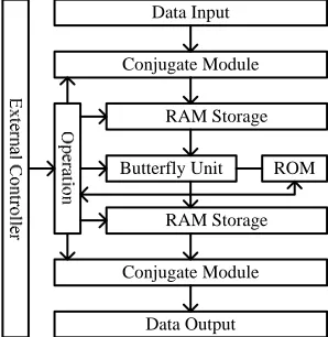
E. Fast Fourier Transform Module
For realization of the FFT as a hardware circuit, the butterfly operation plays an important role [23]. Effective description of the butterfly operation gives small size
Conjugate Module
RAM Storage
Butterfly Unit
RAM Storage
Conjugate Module ROM Data Input
Data Output
circuits of FFT [24]. In this paper, an improved FFT unit is presented. We rearrange the pipeline of butterfly operation and separate the butterfly operation to two levels. The compute results can be saved by their parity rather than ordinal method [25].
The
N
(N
=
2 (
MM
∈
Z
)
) points FFT, for instance, adopt 2M−1 pipeline. They
i present the calculateconsequence of level
j
. The process is1 1
1 1
(2 ) (2 1), [0, )
2 ( )
(2 ) (2 1 ), [ , )
2
j j
j
j j
N
y i y i i
y i
N
y i N y i N i N
− −
− −
⎧ + + ∈
⎪⎪ = ⎨
⎪ − − + − ∈
⎪⎩
(8)
Assume
N
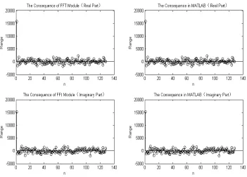
is 8, there have five levels pipeline in the eight points FFT flow. The odd level is only process addition operation and the even level is only process multiplication operation. According to the principle discussed above, we design the FFT Module is shown in Fig. 8.Both the address reading information and the address writing information are saved in ROM and will generate by the function gt_ad_bin_inv and gt_wd_bin_inv of Matlab. The twiddle factor can obtain after using
gt_factor function of MATLAB. Because of the range valued of cos-sin and cos-sin is greater than the cos, the valid digital number should extent from 16bit to 17bit for improve the accurateness. After combining the data to create a mif type file, the LPM-ROM can be generated and download to the FPGA for testing. Putting the consequence of the verifying into MATLAB and comparing with the original data, we can obtain the difference as shown in the Fig. 9.
V. ETHERNETINTERFACE
A. Design of Ethernet Interface
Using Ethernet interface of panoramic mosaic camera, the data packet is sent to the remote client by related network protocols which include RTP/RTCP, UDP, HTTP and TCP/IP. The traditional solution is using TCP/IP protocol stack which is running in the NIOS II processor based on the RTOS of embedded system [26], [27]. Thus, the network structure is divided into four layers: Physical Layer, Data Link Layer, Net Layer and Transfer Layer. To achieve the requirement of real-time performance, a net transmission speed test is set and the result shown in Table I.
From the obvious consequence of the test, the embedded system without both RTOS and TCP/IP stack can satisfy the requirement of real-time performance. Due to the maximum working frequency of SDRAM is 166MHz, the NIOS II have to working on 150MHz [28]. Since the data of this camera is transmission in the Data Link Layer, we can manually program net frame to fulfill the net transmission without both RTOS and net stack.
B. Structure of Net Frame TABLE I.
TYPE SIZES FOR CAMERA-READY PAPERS
Group RTOS TCP/IP stack
NIOS II Frequency
Transmission Speed
1 uCosII LwIP 85MHz 11Mbps 2 uCosII LwIP 120MHz 15Mbps 3 uCosII LwIP 150MHz 19Mbps
4 uCosII - 150MHz 60Mbps
The network physical controller is DMA9000A. It can automatically generate the checksum for the IP package [29]. The net frame for panoramic mosaic camera is shown in Fig. 9.
The Destination MAC is the MAC address of the remote cline and the Source MAC is the MAC address of the camera. The frame type identify the classification of the IP package and the value 0x08 and 0x00 present that this is an IP Frame. The value of UDP Sign is 0x11 and the application of remote cline will handle subsequent data as UDP, although there is no TCP/IP stack in the FPGA embedded system. The Destination IP and Destination Port is key part for remote client to obtain the data and these settings have to correspond with the application program.
C. Design of Remote Client Application
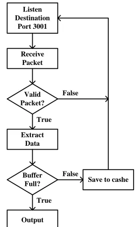
Since remote client application is develop in Java programming language, the requirement for the client computer operating system is not specific [30]. The executive flow of the remote client application shows in Fig. 10.
At very beginning, the application will listen to the destination port 3001 for receive the data packet from the
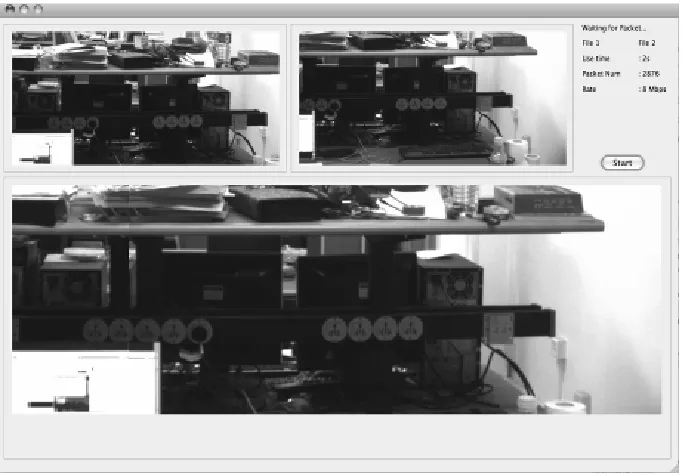
VI. EXPERIMENTALRESULTS
To confirm the behaviors of the proposed Ethernet panoramic camera, experiments to generate panoramic image and transmit through Ethernet are performed. Fig. 11. presents the panoramic situations and the whole system.
The ALTERA DE2-70 FPGA platform, connecting two THDB-D5M CMOS sensors, shows in the left. The local LCD monitor demonstrates the mosaic image from the camera by VGA interface. In the middle is an Ethernet router, which is connecting the camera and remote terminal through unshielded twisted pair. The remote client is Apple MacBook, running Snow Leopard operating system.
Through the two THDB-D5M CMOS sensors can obtain two filed of view. The panoramic camera will combine these two images into a mosaic image and transmit to the remote client through the Ethernet. The remote application acquires the image as the Fig. 12.
VII. CONCLUSION
This paper mainly discusses the design of a panoramic camera with an Ethernet interface. The panoramic perspective was achieved through the optical structure and multiple image sensors. An optimal panoramic mosaic principle which especially for executing in FPAG embedded system is also described. It also elaborated the fulfillment of the method in FPGA embedded system, Algorithm 1 The remote client application executive flow
Input: The packet from Ethernet panoramic camera
Output: Display the frame in to client screen 1: while ServerSocket.Listen(port3001) 2: ServerSocket.Receice(packet) 3: if packet.Valid = True then
4: Get.packet.data 5: if Buffer.Full = Ture then
6: Display.Frame 7: else Buffer.Save.data
8: endif
9: else continue 10: endif
11: endwhile
Figure 10. The structure of the Manual Net Frame.
Valid Packet? Receive Packet
Extract Data
Buffer
Full? Save to cashe
Output True
True False
False
with contained four kernel modules. Moreover, this camera provides the Ethernet interface support which can transmit the panoramic image to the remote client. At last, the evaluation results verified the camera can satisfy the requirements of the panoramic situations.
ACKNOWLEDGMENT
I would like to express my gratitude to all those who have helped me during the writing of this thesis. This
work was supported by a grant from the National Natural Science Foundation of China (No. 10603009 and No. 10673019) and Beijing Nova Program (No. 2008B57).
REFERENCES
[1] Alistair J. Fitch, Alexander Kadyrov, William J. Christmas and Josef Kittler, “Fast Robust Correlation,” IEEE, 2005. [2] J. Cooley and J. Tukey, “An algorithm for the machine
calculation of complex Fourier series,” Math. Comput., vol. 19, pp. 297301, 1965.
[3] L. G. Brown, “Asurvey of image registration techniques,” ACMComput. Surv., vol. 24, no. 2, pp. 325376, Dec. 1992. [4] C. A. Glasbey and N. J. Martin, “Multimodality
microscopy by digital image processing,” J. Microsc., vol. 181, pp. 225237, 1996.
[5] W. K. Pratt, “Correlation techniques of image registration,” IEEE Trans. Aerosp. Electron. Syst., vol. AES-10, pp. 353358, 1974.
[6] F. Ghozzi, P. Nouel, Ph. Marchegay, “Acquisition memorisation video systeme Excalibur,” IEEE Canada, Conference Canadienne en Genie Electrique et Informatique 2003, Montreal, Mai 2003.
[7] D.Lewis and Al, “The StratixTM Routing and Logic Architecture,” FPGA 03, February 23-25, 2003, Monterey, California, USA.
[8] A.Dandalis and V.K.Prasanna, Configuration Compression for FPGAbased Embedded Systems FPGA, 2001, February 11-13, 2001, Monterey, CA, USA.
[9] Kanade T, P.J. Narayanan, P.W. Rander, “Virtualized reality: Concepts and early results,” Proc. IEEE Workshop on Representation of Visual Scenes, 1995.
[10]Wilburn, B., M. Smulski, H-H. Kelin Lee, M. Horowitz, “The Light Field Video Camera,” Proc. Media Processors, SPIE Electronic Imaging, 4674, 2002.
[11]Dodgson, N.A., J.R. Moore, S.R. Lang., “Timemultiplexed autostereoscopic camera system,” Proc. SPIE Symposium on Stereoscopic Displays and Applications VIII, 3012, San Jose CA., 1997.
[12]Szeliski, R., H-Y. Shum, “Creating full view panoramic image mosaics and environment maps,” ACM SIGGRAPH, 251-258, 1997.
(a) The Appearance of Panoramic Mosaic Camera
(b) The Function demonstration of Panoramic Mosaic Camera
Figure 12. The demonstration of Ethernet Panoramic Camera.
Platforms”, Springer Publishing (Berlin), 2005.
[18]Henzinger T A and Sifakis J, “2007 The discipline of embedded systems design,” IEEE Computer 40 32-40, 2007.
[19]Liao R K, Ji Y F and Li H, “Optimized design and implementation of TCP/IP software architecture based on embedded System,” Conf. Proc. On Machine Learning and Cybernetics (Dalian) 590-4, 2006.
[20]Sen Ma, Yuanyuan Shang, et al.. Research on Embedded Surveillance Platform in Severe Environment. Proceeding of the Fifth IEEE International Symposium on Embedded Computing. 2008.8. 47-52.
[21]Shang Yuanyuan, Guan Yong, Ma Sen. The design of 2K x 2K high performance CCD camera for astronomical imaging. Proceeding of the Fifth IEEE International Symposium on Embedded Computing. 2008.8. 127-131. [22]J. G. Tong and M. A. S. Khalid, “Profiling CAD Tools: A
Proposed Classification,” in Proc. of the 19th International Conference on Microelectronics, December 2007, pp. 253– 256.
[23]D. Burger and T. M. Austin, “The SimpleScalar Tool Set Version 2.0,” ACM SIGARCH Computer Architecture News, vol. 25, no. 3, pp. 13–25, June 1997.
[24]R. Lysecky, S. Cotterell, and F. Vahid, “A Fast On-Chip Profiler Memory,” in Proc. of the 39th Conference o Design Automation, June 2002, pp. 28–33.
[25]D. A. Varley, “Practical Experience of the Limitations of gprof,” in Software Practice and Experience, 1993, pp. 461–463.
[26]Intel Corporation, IA-32 Intel Architecture Software Developer’s Manual, Accessed February 2006. [Online]. Available:
http://developers.sun.com/prodtech/cc/articles/pcounters.ht ml
[27]S. Brown, S. Browne, J. Dongarra, N. Garner, K. London, and P. Mucci, “A scalable cross-platform-infrastructure for application performance tuning using hardware-counters,” in Proc. of the 2000 ACM/IEEE conference on Supercomputing, 2000.
[28]L. Shannon and P. Chow, “Maximizing System Performance:
[29]Using Reconfigurability to Monitor System Communications,” in Proc. of the 2004 International Conference on Field Programmable Technology (ICFPT), December 2004, pp. 231–238.
[30]M. R. Guthaus, J. S. Ringenberg, D. Ernst, T. M. Austin, T. Mudge, and R. D. Brown, “MiBench: A Free, Commercial Representative Embedded Benchmark Suite,” in Proc. in the 4th Annual Workshop on Workload Characterization, December 2001, pp. 3–14.