Available online:
https://edupediapublications.org/journals/index.php/IJR/
P a g e | 1 8 6 8Power Quality Improvement in Standalone Microgrids by using
Model Predictive controller
1AKKAYYAGARI NE E HARI KA, 2 M r. GADE SUBBAREDDY
A bs tract :
Hybrid ac/dc microgrids have been planned for the better interconnection of different distributed generation systems (DG) to the power grid, and exploiting the prominent features of both ac and dc microgrids. This paper presents a microgrid consisting of different distributed generation (DG) units that are connected to the distribution grid. An energy-management algorithm is implemented to coordinate the operations of the different DG units in the microgrid for grid-connected and islanded operations. The proposed microgrid consis ts of a photovoltaic (PV) array which functions as the primary generation unit of the microgrid and a proton -exchange membrane fuel cell to supplement the variability in the power generated by the PV array. A lithium-ion storage battery is incorporated into the microgrid to mitigate peak demands during grid-connected operation and to compensate for any shortage in the generated power during islanded operation. The control design for the DG inverters employs a new model predictive control algorithm which enables faster computational time for large power systems by optimizing the steady -state and the transient control problems separately. The design concept is verified through various test scenarios to demonstrate the operational capability of the proposed microgrid, and the obtained results are discussed.
I. INTRODUCTION
The application of distributed power generation has been increasing rapidly in the past decades. Compared to the conventional centralized power generation, distributed generation (DG) units delive r clean and renewable power close to the customer’s end [1]. Therefore, it can alleviate the stress of many conventional transmission and distribution infrastructures. As most of the DG units are interfaced to the grid using power electronics converters, they have the opportunity to realize enhanced power generation through a flexible digital control of the power converters.
The current research is also focused on achieving a smartergrid through demand -side management (DSM), increasing energy reserves and improving the power quality of the distribution system, such as harmonic compensation for nonlinear loads [5]–[8]. The integration of renewable sources can supplement the generation from the distribution grid. However, these renewable sources are intermittent in their generation and might compromise the reliability and stability of the distribution network. As a result, energy - storage devices, such as batteries and ultra-capacitors, are required to compensate for the variability in the renewable sources.
Available online:
https://edupediapublications.org/journals/index.php/IJR/
P a g e | 1 8 6 9II. SYSTEM DESCRIPTION AND MODELING
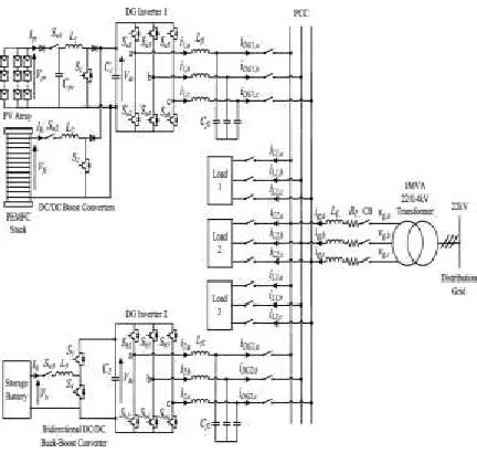
Fig. 1 shows the configuration of the microgrid proposed in this paper that is designed to operate either in the gridconnected or islanded mode. The main DG unit comprises a 40-kW PV array and a 15-kW PEMFC, which are connected in parallel to the dc side of the DG inverter 1 through dc/dc boost converters to regulate the dc -link voltage of the DG inverter at the desired level by delivering the necessary power.
Fig. 1. Overall configuration of the proposed microgrid architecture
The PV array is implemented as the primary generation unit and the PEMFC is used to back up the intermittent generation of the PV array. When there is ample sunlight, the PV array operates in the MPPT mode to deliver maximum dc power PPV, which is discussed in detail in [9] and [10], and the output voltage of the PV array is permitted to vary within an allowable range to ensure proper operation of the DG inverter. To maintain the level of the dc link voltage Vdc at the required level, the PEMFC supplements the generation of the PV array to deliver the necessary Pfc. When the output voltage of the PV array falls below a preset limit, the PV array is disconnected from the DG unit and the PEMFC functions as the main generation unit to deliver the required power. A 30-Ah lithium-ion SB is connected to the dc side of DG inverter 2 through a bidirectlithium-ional dc/dc buck-boost converter to facilitate the charging and discharging operations. During islanded operation, the role of the SB is to maintain the power balance in the microgrid which is given by
PDG+Pb=PL (1)
Where PDG is the power delivered by the main DG unit, Pb is the SB power which is subjected to the charging and discharging constraints given by
Pb ≤Pb, max (2)
PL is the real power delivered to the loads. The energy constraints of the SB are determined based on the state-of-charge (SOC) limits which are given as
Available online:
https://edupediapublications.org/journals/index.php/IJR/
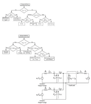
P a g e | 1 8 7 0Fig. 3. Operation of the SB during islanded operation
Although the SOC of the battery cannot be measured directly, it can be determined through several estimation methods presented in [11] and [12]. When the microgrid operates islanded from the distribution grid, the SB can operate in the charging, discharging, or idle mode depending on its SOC and Pb. The flowcharts in Figs. 2 and 3 summarize the operation of the SB based on the output information provided by an energy-management system (EMS) during grid-connected and islanded operation, respectively. The EMS controls and monitors different aspects of power management, such as load forecasting, unit commitment, economic dispatch, and optimal power flow through a centralized server. Important information, such as field measurements from smart meters, transformer tap positions, and circuit- breaker (CB) status are all sent to the centralized server for processing through Ethernet. During grid-connected operation, the distribution grid is connected to the microgrid at the point of common coupling (PCC) through a circuit breaker (CB). The role of the main DG unit functions to p rovide local power and voltage support for the loads and, hence, reduces the burden of generation and delivery of power directly from the distribution grid. With the proliferation of power-electronics equipment being connected to the microgrid, the load currents could be distorted due to the presence of harmonic components. The DG units also function to compensate for any harmonics in the currents drawn by nonlinear loads in the microgrid, so that the harmonics will not propagate to other electrical networks connected to the PCC.
Available online:
https://edupediapublications.org/journals/index.php/IJR/
P a g e | 1 8 7 1can be used to charge the SB or injected into the distribution grid, depending on the SOC of the SB, as shown in Fig. 2. Conversely, when the total load demand is greater than the power generated by the main DG unit, the SB can be controlled to achieve different energy-management functions depending on its SOC and the time of use (TOU) of electricity. During off-peak periods as shown in Fig. 2, when the cost ofgeneration from the grid is low and if the SB’s SOC is below the maximum SOC limit SOCmax, the SB can be charged by the grid and the loads will be supplied by the main DG unit and the grid. During peak periods, when the cost of generation from the grid is high and if the SB’s SOC is above the minimum SOC limit SOCmin, the SB can deliver power to the grid to achie ve peak shaving.
Fig. 4. Equivalent single-phase representation of the DG inverters for grid connected operation.
When a fault occurs on the upstream network of the distribution grid, the CB operates to disconnect the microgrid from the distribution grid. The main DG unit and the SB are the sole power sources left to regulate the loads. In the case when the generation capacity of the main DG unit is unable to meet the total load demand, the SB is required to provide for the shortage in real and reactive power to maintain the power balance and stability of the microgrid as shown in Fig. 3. When the total load demand exceeds the generation capacity of the main DG unit and the SB, the EMS detects a drop in the system frequency and load shedding for noncritical loads is required to restore the system frequency and maintain the stability of the microgrid.
B) DG In v erter M o d elin g
Figs. 4 and 5 show the equivalent single-phase representation of the DG inverters for grid-connected and islanded operation, respectively
Available online:
https://edupediapublications.org/journals/index.php/IJR/
P a g e | 1 8 7 2In the grid-connected mode, the grid voltage is known and the microgrid shares the load demand with the grid. Hence, to control the power delivered to the loads, the output current of the DG inverter is controlled using the current control mode (CCM). During islanded operation, the microgrid will supply the overall load demand as shown in Fig. 5, and it is required that the output voltage be regulated to a pure sine wave with a fixed magnitude. This can be achieved through the voltage-control mode (VCM).With the mathematical model presented in Section II-B, this paper proposes a novel MPC algorithm for the control of the DG inverters of the microgrid. The proposed algorithm is a newly developed MPC algorithm specifically designed for fast -sampling systems, to track periodic signals so as to deal with the dual-mode operation of the microgrid. The algorithm decomposes the MPC optimization into a steady-state sub-problem and a transient sub-problem, which can be solved in parallel in a receding horizon fashion. Furthermore, the steady-state sub problem adopts a dynamic policy approach in which the computational complexity is adjustable. The decomposition also allows the steady-state sub-problem to be solved at a lower rate than the transient sub-problem if necessary. These features help to achieve a lower computational complexity and make it suitable for implementation in a fast-sampling system like our microgrid applications. In the simulation studies in this paper, the sampling interval is chosen as 0.2ms, which is considered pretty small in conventional MPC applications, but necessary for the high order of harmonics being tackled for our problem. According to [16], sampling in the range of tens of kHz is possible with state-of-the- art code generation techniques.
Fig. 7 Overall MPC controller for the DG inverter with E/KF denoting the exogenous Kalman filter and P/KF denoting the plant Kalman filter.
Fig. 8.Schematic Diagram of Simulation Circuit
III. SIM ULA TION STUDIES
The simulation model of the microgrid shown in Fig. 1 is realized in Matlab/Simulink. The microgrid is tested under various conditions to evaluate its capabilities when operating connected and islanded from the distribution grid.
Available online:
https://edupediapublications.org/journals/index.php/IJR/
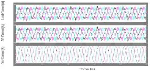
P a g e | 1 8 7 3Fig :11 Three phas e load current, three phas e DG current, and three phas e grid current Fi g9 : Grid ConnectedOperation
Available online:
https://edupediapublications.org/journals/index.php/IJR/
P a g e | 1 8 7 4Fi g :12 Real and reactive power delivered by the main DG unit
Fi g:15 Grid voltage and grid current for phase a Fi g:13 Real and reactive power consumed byloads
Available online:
https://edupediapublications.org/journals/index.php/IJR/
P a g e | 1 8 7 5Fi g:1 6 i s l a nded oper a ti on
Fi g: 19 Real and reactive power delivered by the main DG unit Fi g:17 Per phase currents drawn by loads 1, 2 and3
Available online:
https://edupediapublications.org/journals/index.php/IJR/
P a g e | 1 8 7 6Fig: 20 Real and reactive power cons umed by loads
IV. CONCLUSION
In this project, a control system that coordinates the operation of multiple distributed generation inverters in a microgrid for grid-connected and islanded operations will be presented. The proposed controller for the distributed generation inverters is based on a newly developed model predictive control algorithm which decomposes the control problem into steady-state and transient sub problems in order to reduce the overall computation time.
St udent Det ails:
Ms. AKKAYYAGARI NEEHARIKA was bo r n in I n dia. Sh e p ursuing M.Tech degree in Electrical power sy st em s in E E E Department in Audisankara college of engineering and Technology , Gudur , Nello r e dt , An dh r a P r adesh St at e , I n dia.
m ail id: n eeh ar ik a. 4 4 4 @gm ail. co m
Guide Det ails:
M r. GADE SUBBAREDDY was born in India. He is working as assistant professor at Audisankara college of engineering and technology. He received B.Tech degree in Electrical and Electronics Engineering from Prasad V Potluri Siddhartha institute of technology & M.Tech degree in Power system engineering from RVR and JC college of engineering. His research interests are in the area of power systems especially generation, transmission, dist ribut ion and utilization of elect rical energy and Digit al signal p rocessing.