ISSN (Print) : 2320 – 3765 ISSN (Online): 2278 – 8875
I
nternational
J
ournal of
A
dvanced
R
esearch in
E
lectrical,
E
lectronics and
I
nstrumentation
E
ngineering
(An ISO 3297: 2007 Certified Organization)
Vol. 5, Issue 12, December 2016
Distributed Power-Flow Controller for
Enhancing Power System Stability
Satyanarayana Vanam
Assistant Professor, Department of Electrical and Electronics Engineering, Vagdevi College of Engineering, Warangal, India
ABSTRACT: - The distributed power flow-controller (DPFC) modified from UPFC for increasing system stability and reducing costs. The DPFC can be considered as a UPFC with an eliminated common dc link. The active power exchange between the shunt and series converters, which is through the common dc link in the UPFC, is now through the transmission lines at the third-harmonic frequency. The DPFC has the same control capability as the UPFC, which comprises the adjustment of the line impedance, the transmission angle, and the bus voltage. The objective of this review paper is to study principle of DPFC and analysis the performance to improve the voltage profile. Detailed simulations were carried out to illustrate the control features of these devices.
KEYWORDS: AC-DC power conversion, load flow control, power system control, FACTS, voltage profile, DPFC.
I. INTRODUCTION
Modern power system network is getting much more complicated and heavily loaded than ever before. Many examples show that voltage instability can be the cause of a major blackout. The consequence of such is the risk of stability and reliability of the system and also better utilization of power with minimum loss by installing new FACTS devices such as SSSC, STATCOM, UPFC and DPFC has become crucial [1]. The power system which are heavily loaded, faulted and/or having shortage of reactive power are the main reason for voltage collapse [2]. As the voltage collapse problem is closely related to reactive power planning including the contingency analysis, as these should be considered for the secure operation of the power system [3]. During the outage conditions of some critical lines, the generators are capable of supplying limited reactive power even sometimes the supplied reactive power cannot be used to fulfill the requirement of the network because the location is far from the generator point. Further, the real powers of the generators are reduced to supply the reactive power demand of the system. Hence, the reactive power compensators are used to maintain the voltage profile and thereby improving the performances of the system.
ISSN (Print) : 2320 – 3765 ISSN (Online): 2278 – 8875
I
nternational
J
ournal of
A
dvanced
R
esearch in
E
lectrical,
E
lectronics and
I
nstrumentation
E
ngineering
(An ISO 3297: 2007 Certified Organization)
Vol. 5, Issue 12, December 2016
Fig.1: Simplified representation of a UPFC
For a lower cost and higher stability, the distributed FACTS is invented Distributed FACTS device (D-FACTS) is the concept to use multiple low-power converters attached to the transmission line by single turn transformers [4]. This paper introduces a new concept of distributed power flow controller (DPFC) that combines conventional FACTS and D-FACTS devices. The DPFC gives the possibility of control all system parameters. At the same time, it provides higher reliability and lower cost.
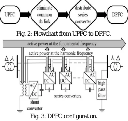
Fig. 2: Flowchart from UPFC to DPFC.
Fig. 3: DPFC configuration.
III. DPFC PRINCIPLE
The DPFC consists of one shunt and several series-connected converters. The shunt converter is similar as a STATCOM, while the series converter employs the D-FACTS concept, which is to use multiple single-phase converters instead of one large rated converter. Each converter within the DPFC is independent and has its own dc capacitor to provide the required dc voltage. The configuration of the DPFC is shown in Fig. 3.As shown, besides the key components, namely the shunt and series converters, the DPFC also requires a high-pass filter that is shunt connected at the other side of the transmission line, and two Y–Δ transformers at each side of the line.
ISSN (Print) : 2320 – 3765 ISSN (Online): 2278 – 8875
I
nternational
J
ournal of
A
dvanced
R
esearch in
E
lectrical,
E
lectronics and
I
nstrumentation
E
ngineering
(An ISO 3297: 2007 Certified Organization)
Vol. 5, Issue 12, December 2016
current. Since the integrals of all the cross product of terms with different frequencies are zero, the active power can be expressed by:
Σ (1)
Equation (1) shows that the active powers at different frequencies are independent from each other and the voltage or current at one frequency has no influence on the active power at other frequencies. The independence of the active power at different frequencies gives the possibility that a converter without a power source can generate active power at one frequency and absorb this power from other frequencies.
The shunt converter can absorb active power from the grid at the fundamental frequency and inject the current back into the line at a harmonic frequency in this case 3rd harmonic frequency. This harmonic current will flow through the transmission line. According to the amount of required active power at the fundamental frequency, the DPFC series converters generate a voltage at the harmonic frequency, thereby absorbing the active power from harmonic components. Assuming a lossless converter, the active power generated at fundamental frequency is equal to the power absorbed from the harmonic frequency. For a better understanding, Fig. 4 indicates how the active power exchanges between the shunt and the series converters in the DPFC system.
The high-pass filter within the DPFC blocks the fundamental frequency components and allows the harmonic components to pass, thereby providing a return path for the harmonic components. The shunt and series converters, the high pass filter and the ground form a closed
loop for the harmonic current.
B. Using third harmonic components
Because of the unique characteristics of third-harmonic frequency components, the third harmonic is selected to exchange the active power in the DPFC. In a three-phase system, the third harmonic in each phase is identical, which is referred to as “zero-sequence.” The zero-sequence harmonic can be naturally blocked by Y–Δ transformers, which are widely used in power system to change voltage level. Therefore, there is no extra filter required to prevent the harmonic leakage to the rest of the network. In addition, by using the third harmonic, the costly high-pass filter, as shown in Fig. 3, can be replaced by a cable that is connected between the neutral point of the Y–Δ transformer on the right side in
Fig. 3 and the ground. Because the Δ winding appears open circuit to the third-harmonic current, all harmonic current
will flow through the Y-winding and concentrate to the grounding cable.
IV. ANALYSIS OF THE DPFC
ISSN (Print) : 2320 – 3765 ISSN (Online): 2278 – 8875
I
nternational
J
ournal of
A
dvanced
R
esearch in
E
lectrical,
E
lectronics and
I
nstrumentation
E
ngineering
(An ISO 3297: 2007 Certified Organization)
Vol. 5, Issue 12, December 2016
Fig. 4: DPFC simplified representation.
The series converters inject a fundamental voltage which is controllable in both magnitude and phase. It absorbs the active power from 3rd harmonic frequency to balance their dc voltages. Based on the superposition theorem, the circuit can be split into two circuits at different frequencies. The two circuits are isolated from each other, and the link between two circuits is the active power balance of each converter, see in Fig. 4.
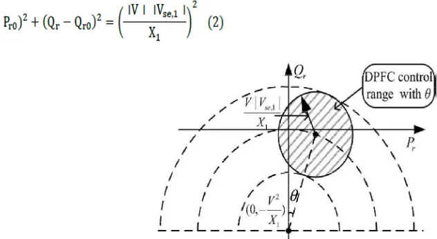
The power-flow control capability of the DPFC can be illustrated by the active power Pr and reactive power Qr received at the receiving end. Since the DPFC circuit at the fundamental frequency behaves the same as the UPFC, the active and reactive power flow can be expressed as follows:
Fig. 5: DPFC active and reactive power control range with the transmission angle θ.
where Pr0 ,Qr0 , and θ are the active, reactive power flow, and the transmission angle of the uncompensated system,
where Pr0 ,Qr0 , and θ are the active, reactive power flow and the transmission angle of the uncompensated system,
Xse,1 = ωLse is the line impedance at fundamental frequency, and |V | is the voltage magnitude at both ends. In the
ISSN (Print) : 2320 – 3765 ISSN (Online): 2278 – 8875
I
nternational
J
ournal of
A
dvanced
R
esearch in
E
lectrical,
E
lectronics and
I
nstrumentation
E
ngineering
(An ISO 3297: 2007 Certified Organization)
Vol. 5, Issue 12, December 2016
maintaining their own converters’ parameters. The central control takes account of the DPFC functions at the power-system level. The function of each controller is listed next.
A. Central Control
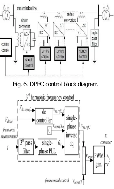
The central control generates the reference signals for both the shunt and series converters of the DPFC. According to the system requirement, the central control gives corresponding voltage-reference signals for the series converters and reactive current signal for the shunt converter. All the reference signals generated by the central control are at the fundamental frequency.
B. Series Control
Every single series converter has its own series control. The controller is used to maintain the capacitor dc voltage of its own converter by using the third-harmonic frequency components and to generate series voltage at the fundamental frequency that is given by the central control loop with the DPFC series converter control.
Fig. 6: DPFC control block diagram.
ISSN (Print) : 2320 – 3765 ISSN (Online): 2278 – 8875
I
nternational
J
ournal of
A
dvanced
R
esearch in
E
lectrical,
E
lectronics and
I
nstrumentation
E
ngineering
(An ISO 3297: 2007 Certified Organization)
Vol. 5, Issue 12, December 2016
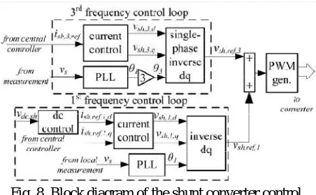
Fig. 8. Block diagram of the shunt converter control.
The principle of the vector control is used here for the dc-voltage control [6]. The third-harmonic current through the line is selected as the rotation reference frame for the single-phase park transformation, because it is easy to be captured by the phase-locked loop (PLL) [7] in the series converter.
C. Shunt Control
The block diagram of the shunt converter control is shown in Fig. 8. The objective of the shunt control is to inject a constant third harmonic current into the line to provide active power for the series converters. A PLL is used to capture the bus-voltage frequency, and the output phase signal of the PLL is multiplied by three to create a virtual rotation reference frame for the third-harmonic component. The control for the fundamental frequency components consists of two cascaded controllers. The current control is the inner control loop, which is to modulate the shunt current at the fundamental frequency. The q-component of the reference signal of the shunt converter is obtained from the central Controller and d-component is generated by the dc control. The shunt converter’s fundamental frequency control aims to inject a controllable reactive current to grid and to keep the capacitor dc voltage at a constant level.
VI. SIMULATION AND RESULTS
Modelling is carried out in MATLAB. The proposed control strategy is implemented using MATLAB / SIMULINK to model DPFC and to analyse the performance to improve voltage profile in power system. The test system is simulated with a three-phase source connected to a non-linear load. The simulation parameters are listed below in Table-1. The supply is connected to load through the parallel transmission lines. For analysing performance of DPFC sample test system is simulated.
To Improve Voltage Profile of given test system DPFC is performed in two operation DPFC in STATCOM mode (Voltage control) and Power flow control by injecting quadrature voltage in series with line voltage.
A. DPFC in STATCOM Mode (Voltage Control)
ISSN (Print) : 2320 – 3765 ISSN (Online): 2278 – 8875
I
nternational
J
ournal of
A
dvanced
R
esearch in
E
lectrical,
E
lectronics and
I
nstrumentation
E
ngineering
(An ISO 3297: 2007 Certified Organization)
Vol. 5, Issue 12, December 2016
B. Operation DPFC in Power-Flow Control mode
ISSN (Print) : 2320 – 3765 ISSN (Online): 2278 – 8875
I
nternational
J
ournal of
A
dvanced
R
esearch in
E
lectrical,
E
lectronics and
I
nstrumentation
E
ngineering
(An ISO 3297: 2007 Certified Organization)
Vol. 5, Issue 12, December 2016
Fig. 10: Outputs of DPFC in STATCOM mode (Voltage Control)
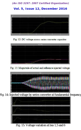
converter and feed back into the system in 3rd harmonic frequency. In this operation 0.1 pu voltage is injected in line-1 at 3rd harmonic frequency and further series converter use this 3rd harmonic active power to charge capacitor voltage and again feed back to the system in fundamental frequency. Series converter will inject voltage
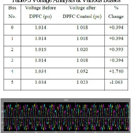
0.1 pu as set in DPFC GUI in quadrature with line voltage. Due to injected voltage power flow of both the parallel line will be changed as shown in graphs. As shunt converter is operating in voltage control mode it will inject reactive power to maintain voltage at sending end and due to change in power flow all bus voltages are affected which is also mentioned in Table-3. Power flow and voltage of important busses are shown in graphs and compared in tables as with and without DPFC controller.
Table-3 Voltage Analysis at Various Busses
ISSN (Print) : 2320 – 3765 ISSN (Online): 2278 – 8875
I
nternational
J
ournal of
A
dvanced
R
esearch in
E
lectrical,
E
lectronics and
I
nstrumentation
E
ngineering
(An ISO 3297: 2007 Certified Organization)
Vol. 5, Issue 12, December 2016
Fig. 14: Injected voltage by series converter at fundamental frequency
Fig. 15: Voltage variation at bus 1,5 and 6
VII. CONCLUSION
The power quality enhancement of the power transmission systems is a vital issue in power industry. In this study, the application of DPFC as a new FACTS device, to improve voltage profile is simulated. The system composed of a three-phase source connected to a linear load through the parallel transmission lines is simulated in Matlab/Simulink environment. In first part of simulation DPFC is performed as STATCOM mode to improve voltage profile and in second portion DPFC is performed to improve voltage profile by controlling power flow in transmission lines. The obtained simulation results show the effectiveness of DPFC in voltage profile improvement.
REFERENCES
[1] Y.-H. Song and A. Johns, Flexible ac Transmission Systems (FACTS) (IEE Power and Energy Series), vol. 30. London, U.K.: Institution of Electrical Engineers, 1999.
ISSN (Print) : 2320 – 3765 ISSN (Online): 2278 – 8875
I
nternational
J
ournal of
A
dvanced
R
esearch in
E
lectrical,
E
lectronics and
I
nstrumentation
E
ngineering
(An ISO 3297: 2007 Certified Organization)
Vol. 5, Issue 12, December 2016
[5] Zhihui Yuan,Sjoerd W.H.de Haan,Jan Braham Ferreira,Dalibor Cvoric”A FACTS Device:Distributed Power Flow Controller(DPFC)’’ IEEE Transactions Power Electronics, vol. 25, no.10, ,pp.2564-2572,October 2010.
[6] Y. Sozer and D. A. Torrey, “Modeling and control of utility interactive inverters,” IEEE Trans. Power Electron., vol. 24, no. 11, pp. 2475–2483, Nov. 2009.
[7] L. Huber, B. T. Irving, and M. M. Jovanovic, “Review and stability analysis of pll-based interleaving control of dcm/ccm boundary boost pfc converters,” IEEE Trans. Power Electron., vol. 24, no. 8, pp. 1992–1999, Aug. 2009.