ISSN (Print) : 2320 – 3765 ISSN (Online): 2278 – 8875
I
nternational
J
ournal of
A
dvanced
R
esearch in
E
lectrical,
E
lectronics and
I
nstrumentation
E
ngineering
(An ISO 3297: 2007 Certified Organization)
Vol. 5, Issue 11, November 2016
Design and Development of Optimized
Asymmetrical 15 Level Inverter Using Genetic
Algorithm
Sunilkumar 1, Madhusudhana J2
Dept. of Electrical Engg, UVCE, Bengaluru, India1
Dept. of Electrical Engg, UVCE, Bengaluru, India2
ABSTRACT: Multilevel inverters have gained increased interest recently as a result of their ability to generate high
quality output waveforms with a low switching frequency. This makes them very attractive for high-power applications. The quality of the output waveform can be increased by eliminating the some lower order dominant harmonics, which can be done by using selective harmonic elimination (SHE) techniques. The simulation is carried out on the proposed topology in MATLAB/Simulink platform for the three cases namely equal step method, Newton-Raphson and Genetic algorithm optimization techniques and a comparative study is made and a better method is chosen. In this paper genetic algorithm optimization technique is employed to generate the optimized switching angles and are fed to a new 15 level asymmetrical inverter topology to eliminate certain lower order harmonics and also to minimize the THD. The optimized angles obtained from GA are fed to pic controller to generate the gating pulses and these pulses are used for triggering the inverter switches in the hardware circuit and a prototype of the proposed topology is developed and tested for the different resistive loads. The obtained results from both hardware and simulation are presented in the result section.
KEYWORDS; multilevel inverter, Genetic algorithm, Newton Raphson, SHE, THD (%),
MATLAB/Simulink
I. INTRODUCTION
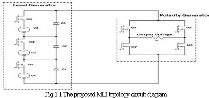
MLI have gained significant attention in recent past due to their numerous advantages. The key concept of MLI is to achieve the power conversion in small voltage steps. The small voltage steps benefit to obtain less switching losses and low harmonic distortion, and devices possessing low voltage ratings and higher efficiency. Also, it performs the reduction of ∂ v/ ∂ t stresses on the load and gives the probability of working with low speed power semiconductor
devices. Such MLI topology improves the efficiency and allows a significant reduction in the size of the output filter. The basic concept of the multilevel inverter is to synthesis the desired AC output voltage from small dc input voltage source. Multilevel inverter are basically categorized in three types, Diode clamped converter [1], flying capacitor MLI [2] and cascade H-bridge MLI [3]. In flying capacitor type of inverter, number of capacitors required will increases as we go for higher levels hence balancing the voltage across the capacitor becomes a major problem. In diode clamped type, as we go for higher levels the number of clamping diodes required is more which makes the system complex. Hence, to overcome the above mentioned drawbacks cascaded H-bridge multilevel inverters can be used [4] [5]. These types of converter are widely used because of their adaptability and simplicity. The cascaded H-bridge multilevel inverter are classified into two type’s symmetrical and asymmetrical converters. In symmetrical type, dc sources of equal voltage values are used for all the H-bridge, whereas in asymmetrical topology the values of voltages sources used are not equal.
ISSN (Print) : 2320 – 3765 ISSN (Online): 2278 – 8875
I
nternational
J
ournal of
A
dvanced
R
esearch in
E
lectrical,
E
lectronics and
I
nstrumentation
E
ngineering
(An ISO 3297: 2007 Certified Organization)
Vol. 5, Issue 11, November 2016
width modulation, space vector modulation, selective harmonic elimination and optimal minimization of total harmonic distortion [7].
It is possible to eliminate the selected harmonics in order to improve the quality of the waveform and to minimize the THD by selective harmonic elimination PWM technique. But the main problem associated with this technique is that, it requires the mathematical solution of nonlinear transcendental equations and as the number of levels increase, the difficulty in solving these equation will also increase. To overcome these drawbacks in this paper we are going for Newton Raphson method and Genetic algorithm optimization technique. The optimal switching angles are calculated using both the techniques in order to eliminate certain lower order harmonics and also to minimize the total harmonic distortion. The obtained optimal switching angles are used in simulation and obtained results are compared and tabulated in the result section. Hardware implementation of the proposed MLI is done and the gate pulses for the switches’ are generated according to the angles obtained from the GA by using DSPIC30F4011.
Fig 1.1 The proposed MLI topology circuit diagram
II. SELECTIVE HARMONIC ELIMINATION FOR CASCADED MULTILEVEL INVERTER
In order to increase the quality of the output power it is necessary to reduce the harmonics present in the output waveform. For reducing the harmonics many methods have been suggested such as Sinusoidal PWM, Space Vector PWM, space vector modulation and selective harmonic elimination. Among those the most effective in eliminating the harmonics is selective harmonic elimination (SHE) method [8]. SPWM and space vector PWM are high frequency switching methods hence these type of techniques causes high switching losses and also requires large filters, whereas the SHE is low frequency switching method so the switching losses will be less. This type of the modulation control technique will limit the harmonic content in the output voltage signal [9].
III. MATHEMATICAL MODELS OF SWITCHING ANGLES AND SHE EQUATIONS FOR A CASCADED MULTILEVEL INVERTER
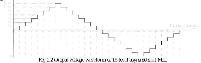
The Fourier series expansion of the output voltage waveform shown in fig 1.2 is expressed as
( ) = ( sin( ) + cos( ))
Since =0, that is the even harmonics are zero due to the quarter wave symmetry of the output voltage, hence only odd harmonics will be present in the waveform and the above equation is written as
The amplitude of the nth harmonic is calculated from the Fourier series factor shown in equation (2) and only first quadrant switching angles are calculated due to the symmetry of the waveform.
ISSN (Print) : 2320 – 3765 ISSN (Online): 2278 – 8875
I
nternational
J
ournal of
A
dvanced
R
esearch in
E
lectrical,
E
lectronics and
I
nstrumentation
E
ngineering
(An ISO 3297: 2007 Certified Organization)
Vol. 5, Issue 11, November 2016
Where k is the variable which represents the switching angles through of the first quadrant, in this case from to
And
0< < < <…….. < (3)
In selective harmonic elimination method, the fundamental harmonic amplitude ( ) is assigned to some desired values of modulating index and amplitude of the harmonics which are to be eliminated are made equal to zero. In this an attempt is made to eliminate 5th and 7th harmonics.
= (4 / ) cos( ) = M = (4 /5 ) cos(5 ) = 0
= (4 /n ) cos(n ) = 0 (4) Where M is the amplitude of the fundamental component.
By solving the above equations obtain the switching angles. Since the above equations are nonlinear transcendental in nature, solving the simultaneous equations becomes difficult. There are several methods has been suggested for solving the SHE-PWM nonlinear equations but in this project only two methods are discussed and they are Newton-Raphson method and genetic algorithm optimization technique.
Fig 1.2 Output voltage waveform of 15 level asymmetrical MLI
IV. NEWTON-RAPHSON METHOD FOR SOLVING THE TRANSCENDENTAL EQUATIONS
It is an iterative method used for solving the SHE equations which are nonlinear in nature. The main disadvantage of this method is, it requires proper initial guess of the switching angles. In this paper NR method is used to reduce the magnitude of the harmonic component such as 5th and 7th present in the output by computing the optimal switching angles for the proposed 15 level inverter. For a particular modulating index the solution is obtained for the SHE nonlinear equations shown in equation (4) and switching angles are computed in the range 0 to π/2 (10). For a
particular range of modulating index different set of solutions can be obtained. This method has some drawbacks such as
A proper initial guess is required for obtaining the solution
It is time consuming and has the computational burden
For different values of modulation indices, it is possible to get more than one solution.
The proposed circuit is simulated for the calculated angles by NR and obtained results are tabulated in the result section. It is found that this method is not effective in removing or in minimizing the selective lower order harmonics and also the THD.
V. GENETIC ALGORITHM OPTIMIZATION TECHNIQUE FOR SOLVING THE TRANSCENDENTAL EQUATIONS
ISSN (Print) : 2320 – 3765 ISSN (Online): 2278 – 8875
I
nternational
J
ournal of
A
dvanced
R
esearch in
E
lectrical,
E
lectronics and
I
nstrumentation
E
ngineering
(An ISO 3297: 2007 Certified Organization)
Vol. 5, Issue 11, November 2016
harmonics as the number of levels increases and it can be applied to any number of levels [11][12]. Hence this algorithm is chosen for the optimizations goals.
Advantages of genetic algorithm
No initial guess is required.
It is not time consuming.
Gives only one solution for one modulation indices.
The advantage of this technique is it starts searching randomly and simultaneously handles large amount of data.
Can be applied to any number of levels.
A. THE ROLE OF GA OPERATION
A. Chromosomes: Every chromosome is taken as a conceivable answer for the issue that is the number of switching
angles required for generating the waveform.
B. Population Size: It is essential to initialize the population size in GA. Based on the nature of problem the population size is decided and the care must be taken such that the time required for computing fitness function is less. Then the GA randomly generates the solutions for entire population size. The population size represents the number of chromosomes in the given population or in single generation.
C. Selection operator: Selection is the first genetic operator applied on the population. The parent chromosomes are selected from the population to create a new offspring or children after the process of recombination. As per the evolution theory i.e., ‘survival of the fittest’ stated by Charles Darwin: The fittest individual should be selected or should survive to produce a new children or offspring. The selection operators are also called as the reproduction operators. The chromosomes which minimizes the fitness function are selected as the best chromosomes.
D. Crossover: Crossover is an operator that combines the characters of the two parent chromosomes to create a new
chromosome or new offspring. The thought behind the recombination is that the new offspring or chromosomes may have better characteristics than the parent chromosomes if from each parent they take a best character.
E.Mutation: Mutation occurs after the recombination process. It is a genetic operator which maintains genetic variability or genetic diversity essential for the evolution process. In a chromosome, the mutation changes the values of one or few genes which results in a new value gene and this is added to a gene pool. The GA might get a better solution with this new value gene compared to the previous.
F. Fitness function: Fitness function is calculated for the new chromosomes produced by the genetic operators and those chromosomes which are more effective in minimizing the fitness function are selected and are used for the circuit operations.
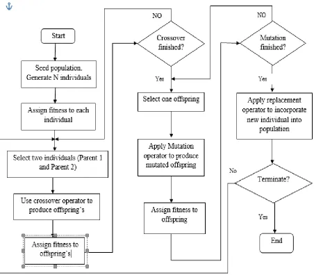
B. ALGORITHM AND FLOW CHART INVOLVED IN GENETIC ALGORITHM OPERATION
The steps involved in expressing a problem and applying GA are as follows
1. The number of variables (in this paper variables refers to the switching angles) specific to the problem is determined and these variables will be the number of genes present in the chromosome. A fifteen level inverter requires seven switching angles that means each chromosome will be having seven switching angles that is seven genes.
2. The second step is initializing the Population size. The accuracy of the solution will increases as the size increases but the drawback in increasing the size of the population is, it increases the execution time. The population size in this paper is considered as 10 that there will be 10 chromosomes and each having 7 genes (switching angles).
3. The next step is to randomly generate the populations of the switching angles according to the number of chromosomes and genes present in the problem. The generated population will be in the range 0 degree to 90 degrees. Such as 0 ≤ α1≤ α2≤…….≤ α7≤ π/2. That is totally 70 switching angles are randomly initialized before applying the
genetic operators.
4. The most important step in GA is evaluating the fitness function. The main objective of this fitness function is to minimize the specific harmonics and also to minimize the THD present in the output. Here THD is considered as the fitness function F( ), that is to be minimized by applying the genetic operators.
%THD= [ ( ) ]
The above equation is taken as the fitness function F( ) and that has to be minimized. i.e minimize F( )= F( , , … … . . )
ISSN (Print) : 2320 – 3765 ISSN (Online): 2278 – 8875
I
nternational
J
ournal of
A
dvanced
R
esearch in
E
lectrical,
E
lectronics and
I
nstrumentation
E
ngineering
(An ISO 3297: 2007 Certified Organization)
Vol. 5, Issue 11, November 2016
= , < , < ……… <
Where , ………….. are the allowable limits of the individual harmonics components and are chosen very close to
zero for eliminating the lower order harmonics such as 5th and 7th.
5. For determining the Fitness function the GA is usually set to run for some iterations (in this case the number of iterations taken is 200). After the first iteration obtained switching angles are selected as reference and new offspring’s are produced by the GA operators such as crossover and mutation. Again the fitness function is evaluated for the new population produced and the process continues until the optimized switching angles are produced. The above mentioned steps of GA are represented in flow chart as shown in fig 1.3.
ISSN (Print) : 2320 – 3765 ISSN (Online): 2278 – 8875
I
nternational
J
ournal of
A
dvanced
R
esearch in
E
lectrical,
E
lectronics and
I
nstrumentation
E
ngineering
(An ISO 3297: 2007 Certified Organization)
Vol. 5, Issue 11, November 2016
VI. SIMULATION AND HARDWARE RESULTS
Fig 1.4 Simulated circuit of proposed 15 level inverter topology
The proposed asymmetrical multilevel inverter is simulated for equal switching angles, Newton-Rephson method and Genetic Algorithm optimization method in the MATLAB/ Simulink software. The input DC voltages sources for inverter are assigned with the magnitudes 45V, 90V and 180V satisfying the ratio 1:2:4 in a binary fashion so as to get 220V RMS at the output voltage which can be used for the grid connected applications. The results are analyzed for a resistive load and the detailed analysis of each of the above simulations has been done and through detailed comparisons, inferences were made on the basis of Total harmonic Distortion, Circuit complexity, voltage stress on devices.
ISSN (Print) : 2320 – 3765 ISSN (Online): 2278 – 8875
I
nternational
J
ournal of
A
dvanced
R
esearch in
E
lectrical,
E
lectronics and
I
nstrumentation
E
ngineering
(An ISO 3297: 2007 Certified Organization)
Vol. 5, Issue 11, November 2016
The above fig 1.5 represents the FFT spectrum of the waveform obtained from the equal angle methods and the THD is found to be 14. 88%.
Fig 1.6 Harmonic analysis of the output obtained NR method across a load of 50 ohms
The above fig 1.6 represents the FFT spectrum of the waveform obtained from the NR method and the THD is found to be 20.87% and 5th and 7th harmonics are found to be large which are eliminated further by using GA
Fig 1.7 Harmonic analysis of the output waveform obtained from GA across a load of 50 ohms
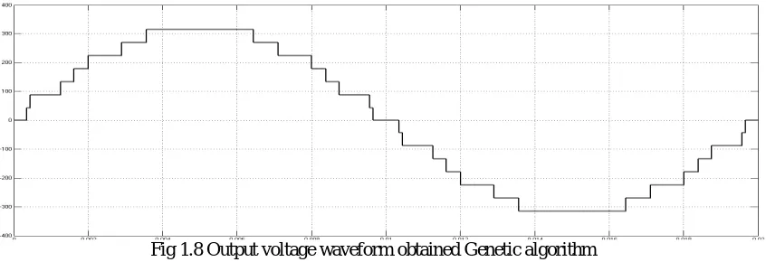
The above fig 1.7 represents the FFT spectrum of the waveform obtained from GA method and the THD is found to be 6.87% and 5th and 7th harmonics are found to be 0.01% and 0.34% respectively.
Fig 1.8 Output voltage waveform obtained Genetic algorithm
ISSN (Print) : 2320 – 3765 ISSN (Online): 2278 – 8875
I
nternational
J
ournal of
A
dvanced
R
esearch in
E
lectrical,
E
lectronics and
I
nstrumentation
E
ngineering
(An ISO 3297: 2007 Certified Organization)
Vol. 5, Issue 11, November 2016
Table 1 Comparison of results obtained from Fig 1.9 Graph of THD in % VS different methods for a different methods for a load of 50 ohms load of 50 ohms
Fig. 2.0 Experimental Setup
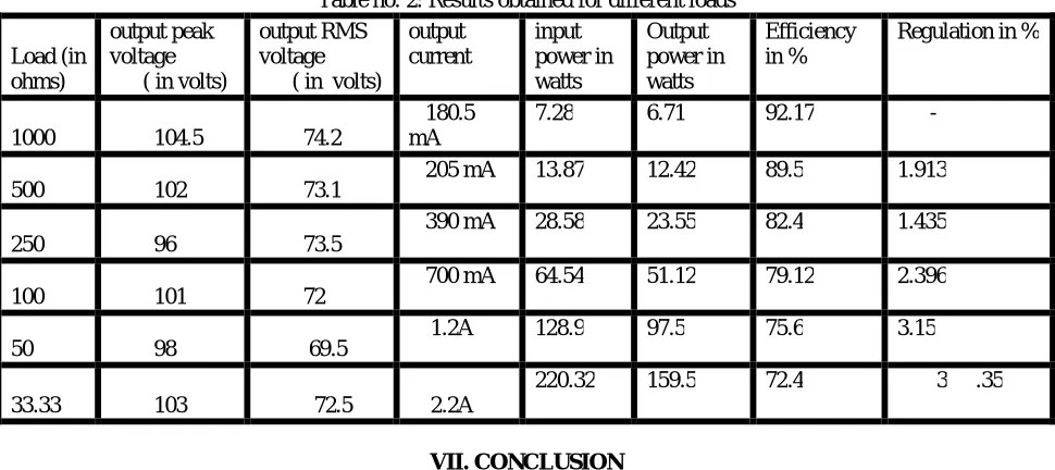
The input voltages are taken as V1 = 15V, V2 = 30V, V3 = 60V from the different variable regulated DC supply and the circuit is tested for resistive loads of 500 ohms, 250 ohms, 100 ohms ,50 ohms and 33.33 ohms and the output power of up to 160 watts has been obtained. The obtained output voltage, output current, output power, efficiency and voltage regulations are tabulated in the below tabular column 2.
Fig 2.1 output voltage waveform obtained for the angles generated by GA
0 5 10 15 20 25
EQUAL ANGLE NR METHOD GA
TECHNIQUE
14.88 20.87
6.87
ISSN (Print) : 2320 – 3765 ISSN (Online): 2278 – 8875
I
nternational
J
ournal of
A
dvanced
R
esearch in
E
lectrical,
E
lectronics and
I
nstrumentation
E
ngineering
(An ISO 3297: 2007 Certified Organization)
Vol. 5, Issue 11, November 2016
Table no. 2: Results obtained for different loads
Load (in ohms)
output peak voltage ( in volts)
output RMS voltage ( in volts)
output current input power in watts Output power in watts Efficiency in %
Regulation in %
1000 104.5 74.2
180.5 mA
7.28 6.71 92.17 -
500 102 73.1 205 mA 13.87 12.42 89.5 1.913
250 96 73.5
390 mA 28.58 23.55 82.4 1.435
100 101 72 700 mA 64.54 51.12 79.12 2.396
50 98 69.5 1.2A 128.9 97.5 75.6 3.15
33.33 103 72.5 2.2A
220.32 159.5 72.4 3 .35
VII. CONCLUSION
The problem of Selective Harmonic Elimination (SHE) in multilevel inverters has been investigated in this paper. Different important solving approaches which are: NR and GA have been considered and are applied on an asymmetrical 15 level hybrid multilevel inverter. The study concludes that Evolutionary Algorithm such as GA is very powerful in solving SHE and results in considerable reduction in the THD compared to iterative techniques such as NR. This topology gives a total harmonic distortion of 6 .87% which is near to the IEEE standards and the ac output voltage waveform almost resembles a sine wave. The proposed circuit is implemented in hardware and the circuit is able to deliver an output of 160 watts with a regulation of 3.3% making it suitable for standalone household applications.
REFERENCES
1. José Rodríguez “Multilevel Inverters: A Survey of Topologies,Controls, and Applications” IEEE TRANSACTIONS ON INDUSTRIAL ELECTRONICS, VOL. 49, NO. 4, AUGUST 2002.
2. Madhusudhana J, P S Puttaswamy, Harshit Agrawal “A comparative analysis of different multilevel inverters” International Journal of Advanced Research in Electrical, Electronics and Instrumentation Engineering(IJAREEIE) Vol. 5, Issue 7, July 2016 ISSN (Print): 2320 – 3765 ISSN (Online): 2278 – 8875. 3. Madhusudhana J, Harshit Agrawal and P S Puttaswamy “A COMPARATIVE ANALYSIS OF 13 AND 15 LEVEL H-BRIDGE MULTILEVEL INVERTERS” International Journal of Morden Trends In Engineering and Research (IJMTER) Vol. 03, Issue8, August 2016 ISSN(Online): 2349-9745, ISSN(Print): 2393-8161.
4. Dhananjaya. Mudadla, Sandeep. N and G Rama rao “Novel Asymmetrical Multilevel Inverter Topology with Reduced Number of Switches for Photovoltaic Applications” 2015 INTERNATIONAL CONFERENCE ON COMPUTATION OF POWER, ENERGY, INFORMATION AND COMMUNICATION, 2015 5. Madhusudhana J, Sunilkumar and P S Puttaswamy “Genetic Algorithm Based 15-Level Modified Multilevel inverter For Stand Alone Photovoltaic systems” International Journal of Morden Trends In Engineering and Research (IJMTER) Vol. 03, Issue8, August 2016 ISSN(Online): 2349-9745, ISSN(Print): 2393-8161.
6. M.Mythili, N.Kayalvizhi “Harmonic Minimization in Multilevel Inverters Using Selective Harmonic Elimination PWM Technique” 2013 International Conference on Renewable Energy and Sustainable Energy [ICRESE’13] DOI: 10.1109/ICRESE.2013.6927790.
7. Madhusudhana J, P S Puttaswamy, sunilkumar “The Paper Analysis And Simulation Of A Simplified 13 Level Multilevel Inverter Using Genetic Algorithm Suitable For PV Systems” International Journal of Advanced Research in Electrical, Electronics and Instrumentation Engineering(IJAREEIE) Vol. 5, Issue 8, August 2016 ISSN (Print): 2320 – 3765 ISSN (Online): 2278 – 8875.
8. Jagdish Kumar, Biswarup Das “Selective Harmonic Elimination Technique for a Multilevel Inverter” Fifteenth National Power Systems Conference (NPSC), IIT Bombay, December 2008 DOI: 0.1109/EESCO.2015.7253677.
9. Zahra Bayat, EbrahimBabaei “Low Order Harmonics Elimination in Multilevel Inverters Using Fuzzy Logic Controller Considering the Variations of DC Voltage Sources” Electrical Machines and Systems (ICEMS), 2011 International Conference on DOI: 10.1109/ICEMS.2011.6073860.
10. T.JEEVABHARATHI, V.PADMATHILAGAM “Harmonic Elimination of Cascade Multilevel Inverters with Non-equal DC Sources Using Particle
Swarm Optimization” 2012 International Conference on Computing, Electronics and Electrical Technologies [ICCEET], DOI:
10.1109/ICCEET.2012.6203775.
11. Zahra Bayatand EbrahimBabaei” Low Order Harmonics Elimination in Multilevel Inverters Using Fuzzy Logic Controller Considering the Variations of DC Voltage Sources”IEEE Conference on Electrical Machines and Systems (ICEMS), pp, 1-6 20-23 Aug. 2011.