ALKALI AGGREGATE REACTION IN NUCLEAR CONCRETE
STRUCTURES: PART 4: MODELLING AND ANALYSIS
A. C. Jurcut1, F. J. Vecchio2, S. A. Sheikh2, D. K. Panesar2, and N. Orbovic3
1
MASc. Student, Dept. of Civil Engineering, University of Toronto, Toronto, Ontario, Canada 2Professor, Dept. of Civil Engineering, University of Toronto, Toronto, Ontario, Canada 3
Technical Specialist, Canadian Nuclear Safety Commission, Ottawa, Ontario, Canada
ABSTRACT
A two-dimensional nonlinear finite element analysis program, VecTor2, was adapted to the analysis of the effects of alkali silica reaction (ASR) (a type of alkali aggregate reaction (AAR)) in concrete structures. The theoretical bases for VecTor2 are the Modified Compression Field Theory (Vecchio and Collins, 1986) and the Disturbed Stress Field Model (Vecchio, 2000) – conceptual models for reinforced concrete based on a smeared rotating-crack macro-modelling approach. This paper focuses on the implementation of ASR constitutive models within the architecture of VecTor2, and on the modelling aspects of ASR-affected elements. The ASR expansion is treated as non-recoverable offset strains using a computational procedure previously developed for elastic and plastic offset strains (Vecchio, 1992).
Two distinct mechanisms have to be taken into account to fully consider the effects of ASR: material expansion and changes in mechanical properties. The ASR-induced expansion may be evaluated, by various alternative models, as: (a) a uniform expansion, equally distributed in all directions; (b) an expansion limited by confinement, independently evaluated in each direction, (c) a volumetric expansion, redistributed in each direction or (d) as a consequence of the gel pressure. The changes in mechanical properties may be calculated as a function of the current free expansion, as recommended by ISE (1992).
The Canadian Nuclear Safety Commission (CNSC) initiated and funded a comprehensive study currently under way at the University of Toronto. The scope and activities to be performed are described in detail by Orbovic et al. (2015). The outcome of this study is anticipated to reveal the implication of concrete deterioration due to ASR on structural integrity and includes material (Gautam et al., 2015) and structural testing (Habibi et al., 2015), and modelling.
Validation studies were performed at both material and structural levels, by modelling ASR-affected specimens reported in the literature. The analytically determined responses currently show reasonable agreement with the experimental results. Accuracy is expected to increase when improved constitutive models are drawn from the material-level investigation (Gautam et al., 2015) and structural testing program (Habibi et al., 2015), concurrent parts of this study.
INTRODUCTION
ASR has been identified as a concrete degradation mechanism for nuclear power plants in Canada. As such, the CNSC initiated a research program having, as its objective, the development of structural assessment criteria for ASR-affected structures by correlating the induced damage with the mechanical and structural effects. The study incorporates three main parts: material testing (Gautam et al., 2015), structural testing (Habibi et al., 2015), and structural analysis and modelling; the latter is the focus of this paper.
observed behavior, predict long-term effects, analyze failure mechanisms, and facilitate possible rehabilitation works.
First, the analytical procedures of VecTor2, a nonlinear finite element analysis program for two-dimensional reinforced concrete structures, are explained with a focus on the procedure by which ASR expansion is accommodated. Second, the manner in which the effects of ASR on the mechanical properties of reinforced concrete are taken into account in VecTor2 is discussed. Next, the results of one of the validation studies performed thus far, involving six reinforced concrete beams tested by Fan and Hanson (1998), are examined. Finally, conclusions that may be drawn at this stage of the study are presented.
METHODOLOGY
VecTor2 is a two-dimensional finite element program, developed at University of Toronto, for the analysis of reinforced concrete membrane structures under static and dynamic loading. The Modified Compression Field Theory (MCFT) and the Disturbed Stress Field Model (DSFM), analytical models for reinforced concrete elements subjected to in-plane normal and shear stresses, form the basis for VecTor2. The program has been enhanced to take into consideration the effects of lateral expansion, triaxial stresses, cyclic loading, construction and loading chronology, and bond-slip.
The MCFT (Vecchio and Collins, 1986) treats concrete as an orthotropic material with rotating uniformly distributed cracks over the element. Compatibility, equilibrium, and constitutive response relationships, formulated in terms of average stresses and average strains, are incorporated in the analysis. An essential feature of the MCFT is the consideration of local stresses and strains at the crack, together with the width and orientation of the cracks. Thus, the failure mechanism may be determined.
The DSFM (Vecchio, 2000) extends the MCFT, enabling improved accuracy in predicting the behaviour for specific types of structures and loading conditions. For elements that exhibit significant shear slip, such as lightly reinforced elements, where the rotation of the principal stress field was found to lag the greater rotation of the principal strain field, the MCFT may overestimate the shear stiffness and strength. Contrarily, the MCFT can underestimate the shear stiffness and strength for elements with limited rotation of the principal stress and strain fields. The DSFM produces improved simulations by incorporating: (a) compatibility relationships which include crack shear slip deformations, decoupling the orientation of the principal stress field from that of the principal strain field, and (b) augmented constitutive relationships for concrete and reinforcement.
VecTor2 utilizes an incremental total load, iterative secant stiffness formulation as the solution procedure. The total strains ሾߝሿ at a point in a reinforced concrete continuum represent the summation of: the net concrete stress-induced strains ሾߝሿ; the elastic concrete strain offsets ሾߝሿ due to mechanisms such as thermal expansion, prestrains, shrinkage, lateral expansion, and ASR; the plastic concrete strain offsets
ൣߝ൧ due to cyclic loading or damage effects; and the strains due to shear slip along the crack ሾߝ௦ሿ. Consequently, the compatibility relationship for concrete is:
ሾߝሿ ൌ ሾߝሿ ሾߝሿ ൣߝ൧ ሾߝ௦ሿ
(1)
ሾߝሿ ൌ ߝߝ௫௬ ߛ௫௬
൩ Ǣሾߝሿ ൌ ߝ௫ ߝ௬ ߛ௫௬
൩ Ǣሾߝሿ ൌ ߝ௫ ߝ௬ ߛ௫௬
Ǣൣߝ൧ ൌ ൦ ߝ௫ ߝ௬ ߛ௫௬
൪ Ǣሾߝ௦ሿ ൌ ߝ௫ ௦ ߝ௬௦ ߛ௫௬௦
(2)
The strain in the ith smeared reinforcement component ሾߝ௦ሿ is comprised of the total strain, elastic offset strain ሾߝ௦ሿ due to thermal or prestrain effects, and plastic offset strain ൣߝ௦൧
due to cyclic loading or material damage, as follows:
ሾߝ௦ሿ ൌ ሾߝሿ ሾߝ௦ሿ ൣߝ௦൧
(3)
The total strains are related to the stresses ሾߪሿ by the composite material stiffness matrix ሾܦሿ, as such:
ሾߪሿ ൌ ሾܦሿሾߝሿ െ ሾߪሿ
(4)
The material stiffness matrix is determined by combining the contributions from the concrete and reinforcement components, in the context of secant-stiffness formulation. Stiffness matrices for concrete
ሾܦሿԢ and for reinforcement components ሾܦ௦ሿԢ are defined with respect to the principal axis, then transformed to the global reference system using appropriate transformation matrices, and summed to form the material stiffness matrix:
ሾܦሿ ൌ ሾܦሿ ሾܦ௦ሿ
ୀଵ
(5)
The pseudo stress vector ሾߪሿ is used to subtract the stress contribution of strain offsets and shear slip strains, such that the element stresses are related only to the net strains of concrete and reinforcement:
ሾߪሿ ൌ ሾܦ
ሿ൛ሾߝሿ ൣߝ൧ ሾߝ௦ሿൟ ሾܦ௦ሿቄሾߝ௦ሿ ൣߝ௦൧ቅ
ୀଵ
(6)
The concrete material stiffness matrix ሾܦሿԢ is defined relative to the principal axis (1, 2), according to the MCFT and DSFM formulations:
ሾܦሿԢ ൌ
ܧതଵ Ͳ Ͳ
Ͳ ܧതଶ Ͳ
Ͳ Ͳ ܩҧ
(7)
The secant moduli ܧതଵ, ܧതଶ, and ܩҧ are evaluated from the current values of the principal stresses, ݂ଵ and ݂ଶ, and corresponding principal net strains, ߝଵ and ߝଶ, as follows:
ܧതଵൌߝ݂ଵ
ଵǢܧതଶൌ ݂ଶ ߝଶǢ ܩҧൌ
ܧതଵή ܧതଶ
ܧതଵ ܧതଶ
(8)
Similarly, the material stiffness matrices for the reinforcement components ሾܦ௦ሿԢ are expressed relative to their longitudinal axes, assuming reinforcement resists only uniaxial stresses:
ሾܦ௦ሿԢ ൌ
ߩܧത௦ Ͳ Ͳ
Ͳ Ͳ Ͳ
Ͳ Ͳ Ͳ൩
(9)
where ߩ is the reinforcement ratio of the ith reinforcement component. The secant modulus ܧത௦ is defined in terms of the current values of the average strains ߝ௦ and stresses ݂௦:
ܧത௦ൌߝ݂௦
௦
(10)
The material stiffness matrices are transformed to the x, y system of axes by means of the transformation matrix:
ሾܦ௦ሿൌ ሾܶ௦ሿ்ሾܦ௦ሿԢሾܶ௦ሿ
(12)
ሾܶሿ ൌ ൦
ʹ߰
ʹ߰
߰ ή
߰
ʹ߰
ʹ߰ െ
߰ ή
߰െ
ʹ
߰ ή
߰ʹ
߰ ή
߰ ൫
ʹ߰ െ
ʹ߰൯൪(13)
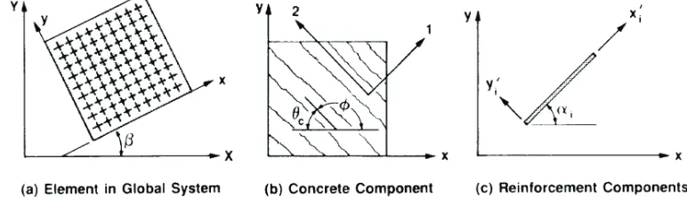
where ሾܶሿ is calculated using ߰ ൌ ߠఙ, the inclination of the principal tensile stress axis, with respect to the positive x-axis, and ሾܶ௦ሿ is evaluated with ߰ ൌ ߙ the orientation of each reinforcement component, with respect to the positive x-axis. The coordinate reference system is shown in Figure 1.
The element stiffness matrix ሾ݇ሿ, relating the nodal forces to the nodal displacements of the element is determined based on the composite material stiffness matrix:
ሾ݇ሿ ൌ නሾܤሿ் ௩
ሾܦሿሾܤሿܸ݀
(14)
where ሾܤሿ is the strain-displacement matrix with the form depending on the element type, which in VecTor2 may be triangular, rectangular of quadrilateral.
Additional details on VecTor2 methodology may be found in “VecTor2 and FormWorks User’s
Manual” (Wong et al. 2013). A similar approach can be taken to expand the analysis methodology to
three-dimensional elements.
Figure 1. VecTor2 coordinate reference systems (adapted from Vecchio, 1990)
MODELLING ASR EFFECTS
To simulate the ASR effects on the structural behaviour of reinforced concrete elements, two mechanisms are considered in VecTor2: induced expansion, and accompanying changes in mechanical properties.
The ASR-induced expansion is treated using methods developed previously for elastic and plastic strain offsets (Vecchio, 1992). In this formulation, briefly presented in the previous section, the material prestrains are considered in the definition of the material stiffness matrix and element nodal forces. Strain offsets are taken into account in the analysis by defining pseudo-stresses reapplied to the element within an iterative algorithm. This procedure has been used to successfully model post-cracking Poisson’s effects, shrinkage, and thermal expansion. However, ASR effects are significantly different from the volume change mechanisms simulated so far with VecTor2. They are directional and time-dependent; long-term stress history influence the magnitude and orientation of ASR strains rather than the instantaneous stress condition, representing a substantially more complex situation.
to the procedure used for handling shrinkage strains. This option yields the highest strains, out of the five models available, as the effect of confining stresses to reduce the expansion is not considered. The other four options represent constitutive models reported in the literature, two of which include a kinetics component for simulating ASR growth in time. The Charlwood (1992) model evaluates ASR strains independently in each direction, limited by the effect of confinement. The Curtis (personal communication, 2014) model is an extension to the Charlwood model, with a refined growth law for concrete in tension. In the Saouma and Perotti (2005) model, which incorporates a kinetics feature, the induced expansion is treated as a volumetric strain redistributed to each principal direction based on weight factors. Provided that sufficient laboratory data are available to describe the free expansion law, the model simulates the expansion as a function of time. Finally, the Sellier (2009) model evaluates AAR strains as a consequence of the gel pressure, which in turn is determined as a function of various parameters describing the gel formation.
Changes in the mechanical properties of concrete (i.e., tensile strength, compressive strength, and modulus of elasticity) are evaluated as percentages of the respective properties of unaffected concrete at 28 days as functions of the free expansion. The lower bounds to the residual properties were implemented from ISE (1992). More recent studies (Giaccio et al., 2008) have shown that a direct correlation between the level of expansion and the change in mechanical properties is insufficient due to the multiple factors involved in their evolution in time including environmental conditions and aggregate type. Nevertheless, the use of ISE (1992) recommendations have provided conservative and satisfactory results so far. Once the material-level investigation (Gautam et al., 2015) is finalized, more accurate reduction functions will be implemented in VecTor2.
The accuracy of the analytical procedure and constitutive models implemented thus far was examined by modelling ASR-affected specimens reported in the literature. Validation studies were carried out at both the material and structural levels. The material-level studies consisted of modelling cylinders, prisms and cubes made with reactive concrete. The effect of AAR on the structural behaviour was assessed by modelling test specimens that included reinforced concrete beams, prestressed concrete beams, and reinforced concrete columns affected by AAR. In what follows, details of some of the analysed specimens are presented together with the results obtained from simulations with VecTor2; comparisons between the analytical and the experimental values are examined and discussed.
FLEXURAL-CRITICAL BEAMS
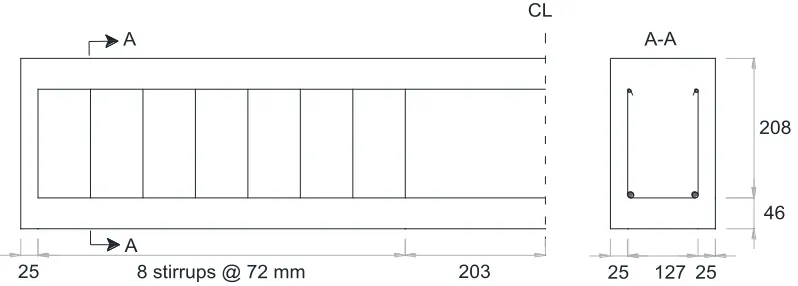
25 8 stirrups @ 72 mm 203 CL
25 127 25
208
46 A
A A-A
Figure 2. Specimen reinforcement (adapted from Fan and Hanson, 1998)
After being cured for 14 days in a standard moisture room, all specimens were placed in a 0.5 N concentration alkali solution. The solution was made by adding 10 grams of NaOH, 14 grams of potassium hydroxide KOH and 0.1 grams of CaO per liter of tap water. The solution was heated to 38°C for a period of 5 to 7 days, upon which it was allowed to cool to around 24°C for 2 days. This procedure continued until the end of the tests. Two of the beams, one reactive and one nonreactive, were loaded during the AAR conditioning period such that cracks of approximately 0.2 mm would develop on the tension face in order to investigate the effect of AAR on beams under service loads. After one year of accelerated conditioning, the beams were tested to failure. During the curing period the expansion was monitored for all beams at three different locations: longitudinal expansion at top of the beams, longitudinal expansion at the level of the reinforcing bars, and transverse expansion. Figure 3 shows the length expansion measurements for beams #3N and #3R. Similar trends of expansion were reported for the other four beams.
Figure 3. Length expansion of beams #3N and #3R (adapted from Fan and Hanson 1998)
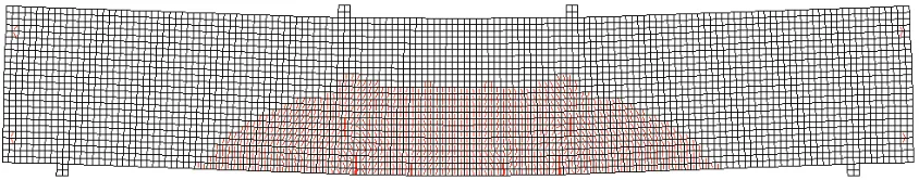
The beams were modelled using VecTor2. The support and loading condition, together with the reinforcement layout and the mesh, are presented in Figure 4. The longitudinal reinforcement was represented as discrete reinforcement, while the stirrups were smeared. The mesh used was 10 mm x 10 mm. Monotonically increasing nodal loads were applied at the locations indicated in Figure 4, similar to
0 200 400 600 800 1000 1200 1400 1600 1800
0 50 100 150 200 250 300 350
Exp
n
a
si
o
n
(
mi
cr
o
str
a
in
)
Time (days) #3R Longitudinal top
#3R Transverse
#3R Longitudinal at level of bars #3N Longitudinal top
#3N Transverse
the test set-up. A bearing material with unidirectional stiffness was modelled at the interface between the bearing steel plates to reduce numerical instability and also to match the support conditions from the test.
Figure 4. Finite element model for Fan and Hanson beam specimens
The concrete properties specified in the analyses were the compressive strength (35 MPa for the nonreactive specimens and 25 MPa for the reactive ones), and the modulus of elasticity (calculated as
͵͵ʹͲඥԢୡ ͻͲͲ MPa). VecTor2 default values were used for all other concrete properties. For the reinforcement, only the yield strength of the longitudinal bars (435 MPa) was specified by Fan and Hanson (1998). The strain hardening and ultimate strain characteristics were not provided. Therefore, a tri-linear response was assumed as shown in Table 1. Two analyses were performed for each test, the variables being the reinforcement properties. As the beams are flexural-critical, the behaviour after the yielding of the reinforcement is sensitive to the strain-hardening phase of the reinforcement.
Table 1. Reinforcement properties
Label fy (MPa) fu (MPa) εsh (x10-3) εu (x10-3) Es (MPa)
fu=1.5*fy 435 653 3.0 125 200,000
fu=1.7*fy 435 783 3.0 125 200,000
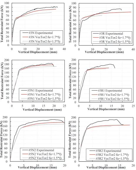
The cracking pattern (Figure 5), as well as the stiffness, displacement at ultimate load, and the ultimate capacity are captured reasonably well by VecTor2. The comparison between the analytical and experimental results are presented in Figure 6. There is a tendency to overestimate the initial stiffness of the ASR-affected beams, which may be a consequence of (a) the prestressing effect of the reinforcement, (b) the compressive stresses induced in concrete due to ASR expansion, or (c) the estimation of Young’s modulus for concrete.
0 10 20 30 40 50 60 70 80 90 100
0 10 20 30 40
T ot al R es trai nt F orc e (kN )
Vertical Displacement (mm) #3R Experimental #3R VecTor2 fu=1.7*fy #3R VecTor2 fu=1.5*fy
0 20 40 60 80 100 120 140 160 180 200
0 5 10 15 20 25
T ot al R es trai nt Force (k N )
Vertical Displacement (mm)
#5R1 Experimental #5R1 VecTor2 fu=1.7*fy #5R1 VecTor2 fu=1.5*fy
0 20 40 60 80 100 120 140 160 180 200
0 5 10 15 20
T ot al R es trai nt F orc e (kN )
Vertical Displacement (mm) #5R2 Experimental #5R2 VecTor2 fu=1.7*fy #5R2 VecTor2 fu=1.5*fy
Figure 6. Results of the flexural loading tests for Fan and Hanson specimens 0 10 20 30 40 50 60 70 80 90 100
0 10 20 30 40
T ot al R es trai nt F orc e (kN )
Vertical Displacement (mm) #3N Experimental #3N VecTor2 fu=1.7*fy #3N VecTor2 fu=1.5*fy
0 20 40 60 80 100 120 140 160 180 200
0 5 10 15 20 25
T ot al R es trai nt F orc e (kN )
Vertical Displacement (mm) #5N1 Experimental #5N1 VecTor2 fu=1.7*fy #5N1 VecTor2 fu=1.5*fy
0 20 40 60 80 100 120 140 160 180 200
0 5 10 15 20
T ot al R es trai nt F orc e (kN )
CONCLUSION
The analyses performed thus far indicate that an analytical formulation using a smeared rotating-crack macro-modelling approach based on the Disturbed Stress Field Model and the Modified Compression Field Theory can provide accurate simulations of the behaviour of ASR-affected specimens. In the material- and structural-level validation studies performed, good correlations were obtained in terms of stiffness, peak load and ultimate displacement as well as damage and crack pattern. Increased accuracy is expected once the constitutive model for ASR, and the degradation of mechanical properties from the material-level study (Gautam et al., 2015), are finalised and implemented.
An investigation of the three-dimensional effects of ASR on the structural behaviour is currently underway. Program VecTor3, the three-dimensional version of VecTor2 applicable to the modelling of reinforced concrete solids, is being modified to accommodate the ASR expansion and the degradation of strength and mechanical properties in the same manner as VecTor2.
Once these analysis tools are completed, they will be useful in developing structural assessment criteria for ASR-affected shear wall elements in nuclear power plant structures.
REFERENCES
Charlwood R G, Solymar S V, Curtis D D. (1992). “A review of alkali aggregate reactions in
hydroelectric plants and dams”, Proceedings of the International Conference of Alkali-Aggregate
Reactions in Hydroelectric Plants and Dams, Volume 129, Fredericton, Canada.
CSA A844-00, (2005) “Guide to the evaluation and management of concrete structures affected by
alkali-aggregate reaction”, CSA International.
Fan, S., and Hanson, J. M. (1998). “Effect of alkali silica reaction expansion and cracking on structural behavior of reinforced concrete beams”, ACI Structural Journal, 95(5), 498-505.
Gautam, B., et al. (2015). “Alkali Aggregate Reaction in Nuclear Concrete Structures: Part 2: Concrete
Materials Aspects”, submitted to SMiRT23, Manchester, U.K.
Giaccio, G., Zerbino, R., Ponce, J. M., and Batic, O. R. (2008). “Mechanical behavior of concretes damaged by alkali-silica reaction”, Cement and Concrete Research,38(7), 993-1004.
Habibi, F., et al. (2015). “Alkali Aggregate Reaction in Nuclear Concrete Structures: Part 1: Structural
Wall Element Aspects”, submitted to SMiRT23, Manchester, U.K.
Institution of Structural Engineers (ISE). (1992). “Structural Effects of Alkali-Silica Reaction”, SETO, London.
Orbovic, N. et al. (2015). “Alkali Aggregate Reaction in Nuclear Concrete Structures: Part 1: A Holistic
Approach”, submitted to SMiRT23, Manchester, U.K.
Saouma, V., and Perotti, L. (2006). “Constitutive model for alkali-aggregate reactions”,ACI materials
journal, 103(3), 194-202.
Sellier, A., Bourdarot, E., Multon, S., Cyr, M., and Grimal, E. (2009), “Combination of structural monitoring and laboratory tests for assessment of alkali-aggregate reaction swelling: application to gate structure dam”,ACI materials journal, 106(3), 281-290.
Vecchio, F.J. (2000). “Disturbed Stress Field Model for Reinforced Concrete: Formulation”, Journal of
Structural Engineering, 126(8), 1070-1077.
Vecchio, F.J., (1990). “Reinforced Concrete Membrane Element Formulations”, Journal of Structural Engineering, 116(3), 730-750.
Vecchio, F.J., (1992). “Finite Element Modelling of Concrete Expansion and Confinement”, ASCE
Journal of Structural Engineering, 118(9), 46-56.
Vecchio, F.J., and Collins, M.P. (1986). “The Modified Compression Field Theory for Reinforced
Concrete Elements Subjected to Shear”, ACI Journal, 83(2), 219-231.
ACKNOWLEDGEMENTS
This work is sponsored by the Canadian Nuclear Safety Commission (CNSC), through Contract
87055-12-0019, “R523.1: Investigation of Consequences of Concrete Alkali Aggregate Reaction on Existing
Nuclear Structures”. Their support is gratefully acknowledged.
NOTATION
ܧ௦: modulus of elasticity of reinforcement ݂௬: steel yield stress
݂௨: steel ultimate stress