555-710-111
Comcode 108522293
Issue 1
October 1999
Integrated System
Release 1.0
Notice Every effort has been made to ensure that the information in this guide is complete and accurate at the time of printing. Information, however, is subject to change. See Appendix A, “Customer Support Information,” in System Programming for important information.
Your Responsibility for Your System’s Security
Toll fraud is the unauthorized use of your telecommunications system by an unauthorized party—for example, persons other than your company’s employees, agents, subcontractors, or persons working on your company’s behalf. Note that there may be a risk of toll fraud associated with your telecommunications system, and, if toll fraud occurs, it can result in substantial additional charges for your telecommunications services. You and your System Manager are responsible for the security of your system, such as programming and configuring your equipment to prevent unauthorized use. The System Manager is also responsible for reading all installation, instruction, and system administration documents provided with this product in order to fully understand the features that can introduce risk of toll fraud and the steps that can be taken to reduce that risk. Lucent Technologies does not warrant that this product is immune from or will prevent unauthorized use of common-carrier telecommunication services or facilities accessed through or connected to it. Lucent Technologies will not be responsible for any charges that result from such unauthorized use. For important information regarding your system and toll fraud, see Appendix A, “Customer Support Information,” in System Programming.
Federal Communica-tions Commission State-ment
This equipment has been tested and found to comply with the limits for a Class A digital device, pursuant to Part 15 of the FCC Rules. These limits are designed to provide reasonable protection against harmful interference when the equipment is operated in a commercial environment. This equipment generates, uses, and can radiate radio frequency energy and, if not installed and used in accordance with the instruction manual, may cause harmful interference to radio communications. Operation of this equipment in a residential area is likely to cause harmful interference, in which case the user will be required to correct the interference at their own expense. For further FCC information, see Appendix A, “Customer Support Information,” in System Programming.
Canadian Department of Communications (DOC) Interference Information
This digital apparatus does not exceed the Class A limits for radio noise emissions set out in the radio interference regulations of the Canadian Department of Communications.
Le Présent Appareil Numérique n’émet pas de bruits radioélectriques dépassant les limites applicables aux appareils numériques de la classe A préscrites dans le réglement sur le brouillage radioélectrique édicté par le
ministère des Communications du Canada.
Year 2000 Compliance The MERLIN MAGIX Integrated System is certified to be Year 2000 compliant. Additional information on this certification, and other issues regarding Year 2000 compliance, is available online at
http://www.lucent.com/enterprise/sig/yr2000.
Trademarks 5ESS, AUDIX, CONVERSANT, CentreVu, DEFINITY, Magic On Hold, MERLIN, MERLIN LEGEND, MERLIN Mail, PARTNER, PassageWay, MLX-10, MLX-20L, MLX-28D, MLS-6, MLS-12, MLS-12D, MLS-18D, MLS-34D, SYSTIMAX, TransTalk, and Voice Power are registered trademarks and 4ESS, Intuity, Lucent Technologies, MERLIN MAGIX, and Prologix are trademarks of Lucent Technologies in the US and other countries.
Acculink, ACCUNET, MEGACOM, MulitiQuest, MLX-5, MLX-5D, MLX-16DP, MLX-10D, MLX-10DP, and NetPROTECT are registered trademarks of AT&T.
Microsoft, Windows, Windows NT, and MS-DOS are registered trademarks of Microsoft Corporation. ProComm and ProComm Plus are registered trademarks of DataStorm Technologies, Inc. Supra, Supra NC, StarSet, and Mirage are registered trademarks of Plantronics, Inc. UNIX is a registered trademark of UNIX System Laboratories, Inc.
PagePac is a registered trademark and Powermate and Zonemate are trademarks of DRACON, a division of Harris Corporation.
Okidata is a registered trademark of Okidata Corporation. Pipeline is a trademark of Ascend Communications, Inc. Intel and Pentium are registered trademarks of Intel Corporation. Apple and Macintosh are registered trademarks of Apple Computer, Inc. IBM is a registered trademark of International Business Machines, Inc. Novell and NetWare are registered trademarks of Novell Corporation. CLASS is a servicemark of Bellcore.
Printed in USAs Issue 1
For more information about Lucent Technologies documents, refer to the section entitled “Related Documents” in “About This Guide” in System Programming.
Support Telephone Number
In the continental US, Lucent Technologies provides a toll-free customer helpline 24 hours a day. Call the Lucent Technologies Helpline at 1 800 628-2888 or your Lucent Technologies authorized dealer if you need assistance when installing, programming, or using your system. Outside the continental US, contact your local Lucent Technologies authorized representative.
Network Engineering Group
For assistance in designing a private network, call the Network Engineering Group at 1 888 297-4700.
Lucent Technologies Corporate Security
Whether or not immediate support is required, all toll fraud incidents involving Lucent Technologies products or services should be reported to Lucent Technologies Corporate Security at 1 800 821-8235. In addition to recording the incident, Lucent Technologies Corporate Security is available for consultation on security issues, investigation support, referral to law enforcement agencies, and educational programs.
Lucent Technologies Fraud Intervention
If you suspect you are being victimized by toll fraud and you need technical support or assistance, call BCS National Service Assistance Center at 1 800 628-2888.
Warranty
Lucent Technologies provides a limited warranty on this product. Refer to “Limited Warranty and Limitation of Liability” in Appendix A, “Customer Support Information,” of System Programming.
Call: BCS Publications Center
Voice 1 800 457-1235 International Voice 317 322-6791 Fax 1 800 457-1764 International Fax 317 322-6699
Write: BCS Publications Center 2855 North Franklin Road Indianapolis, IN 46219-1385
The exclamation point in an equilateral triangle is intended to alert the user to the presence of important operating and maintenance (servicing) instructions in the literature accompanying the product.
To reduce the risk of fire, electrical shock, and injury to persons, follow these basic safety precautions when installing telephone equipment:
■ Read and understand all instructions.
■ Follow all warnings and instructions marked on or packed with the product.
■ Never install telephone wiring during a lightning storm.
■ Never install a telephone jack in a wet location unless the jack is specifically designed for wet
locations.
■ Never touch uninsulated telephone wires or terminals unless the telephone wiring has been
disconnected at the network interface.
■ Use caution when installing or modifying telephone lines.
■ Use only Lucent Technologies-manufactured MERLIN MAGIX Integrated System circuit
modules, carrier assemblies, and power units in the MERLIN MAGIX Integrated System control unit.
■ Use only Lucent Technologies-recommended/approved MERLIN MAGIX Integrated System
accessories.
■ If equipment connected to the MLX telephone modules (008 MLX, 408 GS/LS-MLX, 408
GS/LS-ID-MLX, and 016 MLX) or the ETR telephone module (016 ETR) is to be used for in-range out-of-building (IROB) applications, IROB protectors are required.
■ Do not install this product near water—for example, in a wet basement location.
■ Do not overload wall outlets, as this can result in the risk of fire or electrical shock.
■ The MERLIN MAGIX Integrated System is equipped with a 3-wire grounding-type plug with a
third (grounding) pin. This plug will fit only into a grounding-type power outlet. This is a safety feature. If you are unable to insert the plug into the outlet, contact an electrician to replace the obsolete outlet. Do not defeat the safety purpose of the grounding plug.
■ The MERLIN MAGIX Integrated System requires a supplementary ground.
■ Do not attach the power supply cord to building surfaces. Do not allow anything to rest on the
power cord. Do not locate this product where the cord will be abused by persons walking on it.
■ Slots and openings in the module housings are provided for ventilation. To protect this equipment
from overheating, do not block these openings.
■ Never push objects of any kind into this product through module openings or expansion slots, as
■ Auxiliary equipment includes answering machines, alerts, modems, and fax machines. To
connect one of these devices, you must first have a Multi-Function Module (MFM).
■ Do not operate telephones if chemical gas leakage is suspected in the area. Use telephones
located in some other safe area to report the trouble.
■ To eliminate the risk of personal injury due to electrical shock, DO NOT attempt to install or
remove an MFM from your MLX telephone. Opening or removing the module cover of your telephone may expose you to dangerous voltages.
■ ONLY an authorized technician or dealer representative shall install, set options, or repair an
MFM.
SAVE THESE INSTRUCTIONS
Contents
vi
Contents
About This Guide
xxi
Intended Audience . . . xxi
How to Use This Guide. . . xxi
Terms and Conventions Used . . . xxii
■ Typographical Conventions. . . xxiii
■ Product Safety Advisories . . . xxiii
Security. . . xxiii
Related Documents . . . xxiv
How to Comment on This Guide. . . xxvi
1
Programming Basics
1-1
Overview. . . 1-1 Introduction to System Programming . . . 1-2
■ Planning Forms . . . 1-2
■ Types of Programming . . . 1-2
System Programming Console . . . 1-4
■ Console Components . . . 1-5
■ Console Buttons . . . 1-8
■ Console Overlay . . . 1-9
■ Console and DSS Lights . . . 1-12
Programming Procedures. . . 1-12
■ Procedure Organization . . . 1-12
■ Procedure Contents . . . 1-13
■ Programming Screens . . . 1-13
■ Verifying Data Entry . . . 1-16
■ Saving Entries and Moving among Screens . . . 1-17
■ Using Enter . . . 1-18
■ Using Next. . . 1-18
■ System Programming Hierarchy . . . 1-19
Access to System Programming from the 4424LD+ or MLX-20L or Console . . . 1-19
■ System Programming Menu . . . 1-20
Idle States. . . 1-22
2
Programming with WinSPM
2-1
Overview. . . 2-1 System Requirements . . . 2-2 Installing the WinSPM Software . . . 2-3
■ CD-ROM . . . 2-3
■ Floppy Disks . . . 2-3
Getting Started . . . 2-4
Contents
vii
■ Defining Your Password . . . 2-8
■ Setting Up a Site . . . 2-8
■ Connecting to a MERLIN MAGIX Integrated System . . . 2-13
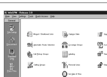
WinSPM Main Screen. . . 2-16 Using Quick Access . . . 2-17
■ Allowed/Disallowed Lists. . . 2-17
■ Automatic Route Selection (ARS) . . . 2-18
■ Call Pickup Groups . . . 2-18
■ Calling Group . . . 2-18
■ Capture Data. . . 2-20
■ Coverage Groups . . . 2-20
■ Labeling. . . 2-21
■ Personal Lines . . . 2-21
■ Set Date and Time . . . 2-22
■ Speed Dial. . . 2-22
■ System Inventory . . . 2-22
■ Telephone Programming. . . 2-23
■ Telephone Restrictions . . . 2-23
WinSPM Help . . . 2-25 Using Standard SPM Mode . . . 2-26
■ SPM Screens . . . 2-26
Basic System Management Procedures. . . 2-28
■ Backup . . . 2-29
■ Boards. . . 2-31
■ Browse . . . 2-34
■ Language . . . 2-36
■ Maintenance . . . 2-37
■ Pass-Thru . . . 2-37
■ Password . . . 2-40
■ Print Options . . . 2-41
■ Restore . . . 2-42
System Programming . . . 2-44
■ Basic Programming Information . . . 2-44
■ Idle States . . . 2-45
■ 100D and 100R Module Idle . . . 2-47
■ Accessing System Programming . . . 2-47
■ Printing Reports . . . 2-48
Surrogate Mode Programming . . . 2-49
3
Programming Procedures
3-1
Overview. . . 3-1 Basic System Operating Conditions . . . 3-1
■ System Restart . . . 3-2
■ System Programming Position Assignment . . . 3-3
Contents
viii
■ Board Renumbering . . . 3-4
■ Mode of Operation . . . 3-5
■ Automatic Maintenance Busy . . . 3-6
■ Set System Date . . . 3-7
■ Set System Time. . . 3-8
System Renumbering . . . 3-9
■ Select System Numbering Plan . . . 3-12
■ Single Renumbering . . . 3-13
■ Block Renumbering. . . 3-14
■ Non-Local Dial Plan Extension Ranges . . . 3-15
■ Direct Station Selector (DSS) Page Buttons . . . 3-18
System Operator Positions . . . 3-19
■ Primary Operator Positions . . . 3-20
■ QCC System Operator Positions . . . 3-20
■ DLC Operator Positions . . . 3-22
Lines and Trunks . . . 3-23
■ Type of Trunk . . . 3-24
■ Outmode Signaling for Loop- or Ground-Start Trunks . . . 3-24
■ Rotary Trunk Digit Transfer. . . 3-25
■ Ringing Frequency . . . 3-26
■ Second Dial Tone Timer . . . 3-26
■ Disconnect Signaling Reliability . . . 3-27
■ Toll Type . . . 3-28
■ Hold Disconnect Interval . . . 3-29
■ Principal User for Personal Line . . . 3-30
■ QCC Queue Priority Level. . . 3-31
■ QCC Operator to Receive Calls . . . 3-32
■ Loop-Start Identification Delay . . . 3-33
■ Clock Synchronization. . . 3-34
■ Trunks to Pools Assignment . . . 3-35
■ Copy Options for Lines/Trunks . . . 3-37
Uniform Dial Plan Facilities. . . 3-38
■ Switch Identifiers . . . 3-38
DS1 Facilities . . . 3-40
■ Activate/Deactivate the On-board CSU. . . 3-41
■ Channel Selection . . . 3-41
■ Type of DS1 Facility . . . 3-41
■ Switched 56 Dial Plan Routing . . . 3-45
■ Frame Format . . . 3-46
■ Zero Code Suppression . . . 3-47
■ Signaling Mode . . . 3-47
■ Line Compensation . . . 3-48
■ Channel Service Unit . . . 3-49
Tie Trunks. . . 3-49
■ Direction . . . 3-50
Contents
ix
■ E&M Signal . . . 3-51
■ Dial Mode . . . 3-52
■ Tie Trunk Dial Tone. . . 3-53
■ Tie Trunk Answer Supervision Time . . . 3-54
■ Disconnect Time . . . 3-54
DID Trunks . . . 3-55
■ Block Assignment . . . 3-55
■ DID Trunk Type. . . 3-56
■ Disconnect Time . . . 3-57
■ Expected Digits . . . 3-57
■ Delete Digits . . . 3-58
■ Add Digits . . . 3-59
■ Signaling . . . 3-59
■ Invalid Destination. . . 3-60
PRI Facilities. . . 3-61
■ Switch Type. . . 3-62
■ Telephone Number . . . 3-63
■ B-Channel Groups . . . 3-64
■ Network Service . . . 3-66
■ Copy Telephone Number to Send. . . 3-67
■ Incoming Routing . . . 3-68
■ Telephone Number to Send . . . 3-69
■ Test Telephone Number . . . 3-70
■ Timers and Counters. . . 3-70
■ Terminal Equipment Identifier . . . 3-73
■ Dial Plan Routing . . . 3-73
■ Outgoing Tables . . . 3-76
■ Network Selection Tables . . . 3-76
■ Special Services Tables . . . 3-77
■ Call-by-Call Service Table. . . 3-79
BRI Facilities. . . 3-81
■ Service Profile Identifier (SPID) and
Directory Number (DN) . . . 3-81
■ Timers . . . 3-82
Extensions . . . 3-83
■ Copy Line/Trunk Assignments . . . 3-86
■ Assign Intercom or System Access Buttons . . . 3-87
■ Rotary Signaling on Tip/Ring Ports . . . 3-91
■ Tip/Ring Functionality on 016 ETR Modules. . . 3-92
Auxiliary Equipment . . . 3-93
■ Music-On-Hold . . . 3-93
■ Loudspeaker Paging . . . 3-94
■ Fax Machines . . . 3-95
■ Maintenance Alarms . . . 3-96
■ Voice Messaging System and Automated Attendant . . . 3-97
Contents
x
■ Programming a CTI Link . . . 3-98
■ CTI Link Programming Errors . . . 3-100
Optional Extension Features . . . 3-103
■ Extension Language . . . 3-103
■ Pool Dial-Out Code . . . 3-104
■ Calling Restrictions . . . 3-105
■ Copy Calling Restrictions . . . 3-107
■ ARS Restriction Level for Extensions . . . 3-108
■ Forced Account Code Entry . . . 3-109
■ Microphone Operation. . . 3-110
■ Authorization Codes . . . 3-110
■ Remote Call Forwarding . . . 3-111
■ Delayed Call Forwarding. . . 3-113
■ Trunk-to-Trunk Transfer . . . 3-114
■ Primary Cover Ring Delay. . . 3-115
■ Secondary Cover Ring Delay . . . 3-115
■ Group Coverage Ring Delay . . . 3-116
■ HotLine . . . 3-117
■ Display Preference . . . 3-118
■ Service Observing. . . 3-118
Optional Operator Features . . . 3-120
■ Operator Hold Timer . . . 3-120
■ DLC Operator Automatic Hold . . . 3-121
QCC Optional Features . . . 3-121
■ Hold Return . . . 3-122
■ Automatic Hold or Release . . . 3-123
■ Queue over Threshold . . . 3-123
■ Elevate Priority . . . 3-124
■ Calls-In-Queue Alert . . . 3-125
■ QCC Operator to Receive Call Types . . . 3-125
■ Call Type Queue Priority Level . . . 3-127
■ Message Center Operation . . . 3-128
■ Extended (Directed) Call Completion . . . 3-128
■ Return Ring . . . 3-129
■ Position Busy Backup . . . 3-130
■ Voice Announce . . . 3-131
Optional Group Features . . . 3-131
■ Pickup Groups. . . 3-132
■ Group Paging . . . 3-132
■ Group Coverage Member Assignments . . . 3-133
■ Group Calling Member Assignments . . . 3-134
■ Group Calling Line/Trunk or Pool Assignments . . . 3-136
■ Priority Call Queuing . . . 3-136
Optional Group Calling Features . . . 3-137
■ Hunt Type . . . 3-138
Contents
xi
■ Group Calling Announcement Interval . . . 3-139
■ Group Calling Repeat Announcement . . . 3-140
■ Group Coverage Receiver . . . 3-140
■ Group Calling Overflow and Thresholds . . . 3-141
■ Group Calling Message-Waiting Indicator. . . 3-142
■ Group Calling Calls-In-Queue Alarm Thresholds . . . 3-143
■ Group Calling External Alert for Calls-In-Queue Alarm. . . 3-144
■ Group Type . . . 3-145
■ Queue Control. . . 3-146
System Features. . . 3-148
■ Transfer Return Time . . . 3-149
■ One-Touch Transfer/One-Touch Hold . . . 3-149
■ Transfer Audible . . . 3-150
■ Type of Transfer . . . 3-151
■ Camp-On Return Time . . . 3-152
■ Call Park Return Time. . . 3-152
■ Automatic Callback Interval. . . 3-153
■ Extension Status . . . 3-153
■ SMDR Language. . . 3-154
■ SMDR Call Report Format . . . 3-155
■ SMDR Call Length . . . 3-155
■ SMDR Calls Recorded on Call Report . . . 3-156
■ SMDR Account Code Format . . . 3-157
■ SMDR Talk Time. . . 3-157
■ SMDR UDP Calls Recorded on Call Report . . . 3-158
■ Inside Dial Tone . . . 3-159
■ Reminder Service Cancel . . . 3-159
■ Redirect Outside Calls to Unassigned Extension Numbers . . . 3-160
■ Host System Dial Codes for Behind Switch Mode . . . 3-161
■ Recall Timer . . . 3-162
■ Interdigit Timers . . . 3-162
■ Allowed Lists . . . 3-163
■ Assign Allowed Lists to Extensions. . . 3-163
■ Disallowed Lists . . . 3-164
■ Assign Disallowed Lists to Extensions . . . 3-165
Remote Access Features . . . 3-165
■ Remote Access over Networked Tandem PRI
and Tie Trunks . . . 3-167
■ Remote Access Trunk Assignment . . . 3-168
■ Remote Access Automatic Callback . . . 3-169
■ Remote Access without Barrier Codes . . . 3-170
■ Remote Access Barrier Codes . . . 3-172
■ Remote Access with Barrier Codes . . . 3-174
Automatic Route Selection . . . 3-175
■ ARS over Private Networked Tandem PRI and Tie Trunks . . . 3-175
■ 1 + 7-Digit Dialing Requirements . . . 3-177
Contents
xii
■ Start and Stop Times for Subpatterns. . . 3-178
■ Pool Routing . . . 3-179
■ Facility Restriction Level . . . 3-180
■ Digit Absorption. . . 3-182
■ Other Digits . . . 3-183
■ N11 Special Numbers Tables . . . 3-184
■ Dial 0 Table . . . 3-185
■ Voice and/or Data Routing . . . 3-185
Uniform Dial Plan Routing . . . 3-186
■ UDP Pool Routing . . . 3-187
■ UDP Facility Restriction Level. . . 3-188
■ UDP Digit Absorption . . . 3-189
■ UDP Other Digits. . . 3-190
■ UDP Voice and/or Data Routing . . . 3-191
Night Service . . . 3-191
■ Night Service Group Assignment . . . 3-192
■ Night Service with Outward Restriction. . . 3-193
■ Night Service with Time Set . . . 3-194
■ Night Service with Coverage Control . . . 3-195
Labeling . . . 3-196
■ Extension Directory . . . 3-196
■ Lines or Trunks . . . 3-197
■ Posted Message . . . 3-198
■ Group Calling . . . 3-198
■ System Speed Dial Directory . . . 3-199
Print Reports. . . 3-200
■ Report Language . . . 3-200
■ Printing System Reports . . . 3-201
Data Features . . . 3-204
■ 2B Data . . . 3-205
Memory Card . . . 3-206
■ Card Types . . . 3-206
■ Inserting the Card . . . 3-208
■ Memory Card Formatting . . . 3-209
■ Backup . . . 3-211
■ Automatic Backup . . . 3-212
■ Backup Messages. . . 3-214
■ Restore . . . 3-216
■ Restore Messages . . . 3-217
4
Centralized Telephone Programming
4-1
Contents
xiii
■ Programming Codes . . . 4-6
■ Using the List Feature Menu . . . 4-11
Copy Extension. . . 4-12
■ Features That Can Be Copied . . . 4-12
Feature Quick Reference . . . 4-17
■ Account Code Entry . . . 4-17
■ Alarm. . . 4-17
■ Authorization Code . . . 4-18
■ Auto Dial . . . 4-18
■ Automatic Line Selection. . . 4-18
■ Barge-In . . . 4-19
■ Callback . . . 4-19
■ Caller Number and Name on Caller ID . . . 4-20
■ Call Waiting . . . 4-20
■ Camp-On. . . 4-21
■ Conference . . . 4-21
■ Coverage. . . 4-22
■ Data Status . . . 4-23
■ Direct Voice Mail . . . 4-23
■ Do Not Disturb. . . 4-24
■ Drop . . . 4-24
■ Extension Status . . . 4-25
■ Feature Button . . . 4-25
■ Forward . . . 4-26
■ Group Calling . . . 4-26
■ Calling Group Supervisor . . . 4-27
■ Group Page Auto Dial Button . . . 4-27
■ Headset. . . 4-28
■ Redial . . . 4-29
■ Messaging. . . 4-29
■ Night Service. . . 4-31
■ Notify . . . 4-31
■ Park. . . 4-32
■ Park Zone Auto Dial . . . 4-32
■ Personal Speed Dial . . . 4-32
■ Pickup . . . 4-33
■ Privacy . . . 4-33
■ Recall . . . 4-34
■ Reminder Service . . . 4-34
■ Ringing/Idle Line Preference. . . 4-35
■ Ringing Options. . . 4-35
■ Saved Number Dial . . . 4-37
■ Send/Remove Message . . . 4-37
■ Service Observing. . . 4-37
■ Signaling . . . 4-38
■ System Access/Intercom Buttons . . . 4-38
Contents
xiv
■ Transfer. . . 4-40
■ Voice Announce . . . 4-40
A
Customer Support Information
A-1
Support Telephone Number . . . A-1 Federal Communications Commission (FCC)
Electromagnetic Interference Information. . . A-1 Canadian Department of Communications
(DOC) Interference Information . . . A-1 FCC Notification and Repair Information . . . A-2 Installation and Operational Procedures. . . A-3 DOC Notification and Repair Information . . . A-4 Renseignements sur la Notification du
Ministère des Communications du Canada et
la Réparation . . . A-5 Security of Your System: Preventing Toll Fraud. . . A-7 Toll Fraud Prevention . . . A-8
■ Physical Security, Social Engineering, and
General Security Measures. . . A-8
■ Security Risks Associated with Transferring
through Voice Messaging Systems. . . A-9
■ Security Risks Associated with the Automated
Attendant Feature of Voice Messaging Systems . . . A-11
■ Security Risks Associated with the Remote
Access Feature . . . A-12 Other Security Hints . . . A-13
■ Educating Users . . . A-13
■ Educating Operators . . . A-14
■ Detecting Toll Fraud . . . A-14
■ Establishing a Policy . . . A-15
■ Choosing Passwords . . . A-15
■ Physical Security. . . A-16
■ Limiting Outcalling. . . A-16
Limited Warranty and Limitation of Liability . . . A-16
■ Limitation of Liability . . . A-17
Remote Administration and Maintenance. . . A-18
B
Menu Hierarchy
B-1
Overview. . . B-1
C
LED Displays
C-1
Contents
xv
D
General Feature Use and Telephone Programming
D-1
General Feature Use Information . . . D-1
■ Fixed Features . . . D-1
■ Programmed Buttons . . . D-1
■ Feature Codes . . . D-2
Telephone and Operator Features . . . D-3 Telephone Programming . . . D-32
■ Programming Methods . . . D-32
E
Button Diagrams
E-1
4400-Series Telephones. . . E-1 MLX Telephones. . . E-3 ETR and MLS Telephones . . . E-6 TransTalk MDW 9031 Telephone. . . E-15 Business Cordless 905 Telephone . . . E-16
F
Sample Reports
F-1
Overview. . . F-1 System Information Report . . . F-6 Dial Plan Report . . . F-7 Non-Local Dial Plan Report . . . F-10 Label Information Report . . . F-11 Tie Trunk Information Report . . . F-12 DID Trunk Information Report. . . F-13 GS/LS Trunk Information Report . . . F-14 General Trunk Information Report . . . F-15 DS1 Information Report . . . F-16 PRI Information Report . . . F-17 Remote Access (DISA) Information Report . . . F-21 Operator Information Report. . . F-22 Allowed Lists Report . . . F-24 Access to Allowed Lists Report . . . F-25 Disallowed Lists Report . . . F-26 Access to Disallowed Lists Report . . . F-27 Automatic Route Selection Report . . . F-28 Extension Directory Report. . . F-30 System Directory Report. . . F-31 Group Paging Report . . . F-32 Extension Information Report . . . F-33
Extension Information Report—Continued . . . F-34
Contents
xvi
Group Call Pickup Report . . . F-38 Error Log Report . . . F-39 Authorization Code Information Report . . . F-40 BRI Information Report . . . F-41 Switch 56 Data Information Report. . . F-42
G
General System Programming Sequence
G-1
Basic System Operating Conditions . . . G-1 System Renumbering . . . G-2 Identify System Operator Positions . . . G-2 Lines and Trunks . . . G-2 Complex Lines . . . G-3 Telephones . . . G-3 Auxiliary Equipment . . . G-4 Print Reports. . . G-4
H
Programming Special Characters
H-1
4400 and Single-Line Telephones . . . H-1 4400D and Multiline 4400-Series Telephones . . . H-2 MLX-10 and MLX-5 Non-Display Telephones . . . H-3 MLX Display Telephones . . . H-4 ETR and MLS Non-Display Telephones. . . H-5 ETR and MLS Display Telephones. . . H-6
GL Glossary
GL-1
List of Figures
xvii
List of Figures
1
Programming Basics
1-1 4424LD+ Telephone . . . 1-4
1-2 MLX-20L Telephone . . . 1-5
1-3 4424LD+ Display Buttons and Main Menu . . . 1-8
1-4 MLX-20L Display Buttons and Main Menu . . . 1-8
1-5 4424LD+ System Programming Console Overlay . . . 1-10
1-6 MLX-20L System Programming Console Overlay . . . 1-11
1-7 Selecting a Block of Lines/Trunks . . . 1-11
1-8 Information Screen . . . 1-14
1-9 Menu Selection Screen . . . 1-14
1-10 Data Entry Screen . . . 1-15 1-11 Inspect Example . . . 1-16 1-12 Sample Inspect Screen . . . 1-16 1-13 Screen Keys . . . 1-17 1-14 System Programming Menu Screens . . . 1-20
2
Programming with WinSPM
2-1 WinSPM Main Screen . . . 2-4
2-2 Direct Connection . . . 2-13
2-3 Direct Connection, PC More Than 50 Feet Away . . . 2-14
2-4 Internal Connection . . . 2-14
2-5 External Connection . . . 2-15
2-6 WinSPM Main Screen . . . 2-16
2-7 Sample WinSPM Help Screen . . . 2-25
2-8 Standard SPM Mode Display . . . 2-26
2-9 Pass-Thru . . . 2-37
3
Programming Procedures
3-1 2-Digit Numbering . . . 3-10
3-2 3-Digit Numbering . . . 3-11
3-3 Set-Up-Space Numbering . . . 3-11
3-4 PCMCIA Memory Card . . . 3-207
3-5 Inserting the Memory Card . . . 3-208
E Button Diagrams
E-1 4412D+, 4424D+, and 4424LD+ Telephones (Hybrid/PBX Mode) . . . E-1
E-2 4406D+ Telephone (Hybrid/PBX Mode) . . . E-1
E-3 4412D+, 4424D+, and 4424LD+ Telephones (Key and Behind Switch Modes) . . . E-2
E-4 4406D+ Telephone (Key and Behind Switch Modes) . . . E-2
E-5 MLX-20L and MLX-28D Telephones (Hybrid/PBX Mode) . . . E-3
E-6 MLX-16DP Telephone (Hybrid/PBX Mode) . . . E-3
E-7 MLX 5- and 10-Button Telephones (Hybrid/PBX Mode) . . . E-4
List of Figures
xviii
E-9 MLX-16DP Telephone (Key and Behind Switch Modes) . . . E-5
E-10 MLX 5- and 10-Button Telephones (Key and Behind Switch Modes) . . . E-5
E-11 ETR-34D Telephone (Hybrid/PBX Mode) . . . E-6
E-12 ETR-18/18D Telephones (Hybrid/PBX Mode) . . . E-6
E-13 ETR-6 Telephone (Hybrid/PBX Mode) . . . E-7
E-14 MLS-34D Telephone (Hybrid/PBX Mode) . . . E-7
E-15 MLS-18D Telephone (Hybrid/PBX Mode) . . . E-7
E-16 MLS-12/12D Telephones (Hybrid/PBX Mode) . . . E-8
E-17 MLS-6 Telephone (Hybrid/PBX Mode) . . . E-8
E-18 ETR-34D Telephone (Key Mode) . . . E-9
E-19 ETR-18/18D Telephones (Key Mode) . . . E-9
E-20 ETR-6 Telephone (Key Mode) . . . E-10
E-21 MLS-34D Telephone (Key Mode) . . . E-10
E-22 MLS-18D Telephone (Key Mode) . . . E-10
E-23 MLS-12/12D Telephones (Key Mode) . . . E-11
E-24 MLS-6 Telephone (Key Mode) . . . E-11
E-25 ETR-34D Telephone (Behind Switch Mode) . . . E-12
E-26 ETR-18/18D Telephone (Behind Switch Mode) . . . E-12
E-27 ETR-6 Telephone (Behind Switch Mode) . . . E-13
E-28 MLS-34D Telephone (Behind Switch Mode) . . . E-13
E-29 MLS-18D Telephone (Behind Switch Mode) . . . E-13
E-30 MLS-12/12D (Behind Switch Mode) . . . E-14
E-31 MLS-6 Telephone (Behind Switch Mode) . . . E-14
E-32 TransTalk MDW 9031 Telephone (Hybrid/PBX Mode) . . . E-15
E-33 TransTalk MDW 9031 Telephone (Key Mode) . . . E-15
E-34 TransTalk MDW 9031 Telephone (Behind Switch Mode) . . . E-15
E-35 Business Cordless 905 Telephone (Hybrid/PBX Mode) . . . E-16
E-36 Business Cordless 905 Telephone (Hybrid/PBX Mode) . . . E-16
List of Tables
xix
List of Tables
1
Programming Basics
1-1 4424LD+ and MLX-20L Console Components . . . 1-5 1-2 Direct Station Selector (DSS) Components . . . 1-7 1-3 Fixed Display Buttons . . . 1-9 1-4 Screen Keys . . . 1-17 1-5 System Programming Menu Options . . . 1-20 1-6 Exiting System Programming . . . 1-21
2
Programming with WinSPM
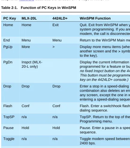
2-1 Function of PC Keys in WinSPM . . . 2-27 2-2 Management Procedures . . . 2-29 2-3 Board Types . . . 2-32
3
Programming Procedures
3-1 Maximum Number of Operator Positions . . . 3-20 3-2 Switched 56 Data Signaling Options . . . 3-45 3-3 Timers and Counters . . . 3-72 3-4 Special Services Table . . . 3-78 3-5 Timers . . . 3-82 3-6 Programming Codes for Assigning Buttons . . . 3-90 3-7 Other Data Programming Procedures . . . 3-204 3-8 Memory Card Formatting Messages . . . 3-210
4
Centralized Telephone Programming
4-1 Features and Programming Codes . . . 4-6 4-2 Features That Can Be Copied: All Telephones . . . 4-12 4-3 Features That Can Be Copied: Direct-Line Consoles Only . . . 4-15
C LED Displays
List of Tables
xx
D General Feature Use and Telephone Programming
D-1 Telephone and Operator Features for MLX Telephones . . . D-4 D-2 Telephone and Operator Features for Multiline 4400-Series Telephones . . . D-13 D-3 Telephone Features for 4400, 4400D, and Single-Line Telephones . . . D-22 D-4 Telephone Features for ETR and MLS Telephones . . . D-25 D-5 Programming 4406D+ Telephones . . . D-33 D-6 Programming 4412D+, 4424D+, and 4424LD+ Telephones by Using the
Display . . . D-33 D-7 Programming MLX-10 and MLX-5 Nondisplay Telephones . . . D-36 D-8 Programming MLX Telephones by Using the Display. . . D-36 D-9 Programming ETR and MLS Telephones . . . D-38 D-10Programming TransTalk MDW 9000 Telephones. . . D-39
F Sample Reports
F-1 Sample Report Pages . . . F-1 F-2 System Reports. . . F-2
H Programming Special Characters
About This Guide
xxi Intended Audience
About This Guide
0The power and versatility of the MERLIN MAGIX Integrated System is due in part to its many options and features. These options and features have been recorded on system planning forms and initially programmed at the time of installation. Changes in use patterns, the addition of new equipment, or a change in operating mode may necessitate additional system programming.
Intended Audience
0This guide is intended for System Managers—those personnel who plan, program, maintain, and manage the system. It is also intended for qualified support personnel who are responsible for installation and initial system programming.
How to Use This Guide
0This guide contains all the programming procedures you need to enable your system to function at peak efficiency. Refer to the following documents for additional information:
■ Feature Reference describes features in detail and any feature interaction. ■ System Planning describes the System Planning Forms and their use.
‘‘Related Documents,” later in this section, provides a complete list of system documentation,
together with ordering information.
In the USA only, Lucent Technologies provides a toll-free customer Helpline 24 hours a day. Call
the Helpline at 1 800 628-2888 (consultation charges may apply), or contact your Lucent Technologies representative if you need assistance when installing, programming, or using your system.
Outside the USA, if you need assistance when installing, programming, or using your system,
About This Guide
xxii Terms and Conventions Used
Terms and Conventions Used
0The terms described here are used in preference to other, equally acceptable terms for describing communications systems.
Lines, Trunks, and Facilities
0Facility is a general term that designates a communications path between a telephone system and the telephone company central office. Technically, a trunk connects a switch to a switch—for example, the MERLIN MAGIX Integrated System to the central office. Technically, a line is a loop-start facility or a communications path that does not connect switches—for example, an intercom line or a Centrex line. In actual usage, however, the terms line and trunk are often applied interchangeably. In this guide, we use line/trunk and lines/trunks to refer to facilities in general. Specifically, we refer to digital facilities. We also use specific terms such as Personal Line, ground-start trunk, Direct Inward Dialing (DID) trunk, and so on. When you talk to personnel at your local telephone company central office, ask them which terms they use for the specific facilities they connect to your system.
Some older terms have been replaced with newer terms, as follows:
Old Term New Term
trunk module line/trunk module
trunk jack line/trunk jack
station extension
station jack extension jack
analog data station modem data workstation
digital data station terminal adapter workstation
7500B data station ISDN terminal adapter data workstation
analog voice and analog data station analog voice and modem data workstation digital voice and analog data station MLX voice and modem data workstation analog data-only station modem data-only workstation
digital data-only station terminal adapter data-only workstation 7500B data-only station ISDN terminal adapter data-only workstation digital voice and digital data station MLX voice and terminal adapter workstation
About This Guide
xxiii Security
Typographical Conventions
0Certain type fonts and styles act as visual cues to help you rapidly understand the information presented:
Product Safety Advisories
0Throughout these documents, hazardous situations are indicated by an exclamation point inside a triangle and the word CAUTION or WARNING.
WARNING:
Warning indicates the presence of a hazard that could cause death or severe personal injury if the hazard is not avoided.
CAUTION:
Caution indicates the presence of a hazard that could cause minor personal injury or property damage if the hazard is not avoided.
Security
0Certain features of the system can be protected by passwords to prevent unauthorized users from abusing the system. You should assign passwords wherever possible and limit distribution of such passwords to three or fewer people.
Nondisplaying authorization codes and telephone numbers provide another layer of security. For more information, see Appendix A, ‘‘Customer Support Information.”
Throughout this guide, toll fraud security hazards are indicated by an exclamation point inside a triangle and the words SECURITY ALERT.
Convention Example
Italics or bold indicate emphasis. It is very important that you follow these steps.
WARNING:
Do not remove modules from the carrier without following proper procedures.
Italics also set off special terms. The part of the headset that fits over one or both ears is called a headpiece.
Plain constant-width type indicates text that appears on the telephone display or PC screen, as well as characters you dial at the telephone or type at the PC.
About This Guide
xxiv Related Documents
SECURITY ALERT:
Security Alert indicates the presence of a toll fraud security hazard. Toll fraud is the
unauthorized use of your telecommunications system, or use by an unauthorized party (e.g., persons other than your company’s employees, agents, subcontractors, or persons working on your company’s behalf). Be sure to read “Security of Your System: Preventing Toll Fraud: in Appendix A, “Customer Support Information” and “Your Responsibility for Your System’s Security” in the “Copyright and Legal Notices” section at the beginning of this document.
Related Documents
0The documents listed in the following table are part of the MERLIN MAGIX documentation set. Within the continental United States, contact the Lucent Technologies BCS Publications Center by calling 1 800 457-1235.
Document No. Title System Documents:
555-710-100 Customer Documentation Package:
Consists of paper versions of the System Manager’s Quick Reference, the Feature Reference, and System
Programming
555-710-110 Feature Reference
555-710-111 System Programming
555-670-112 MERLIN LEGEND® Communications System, Release 7.0, System Planning
555-710-112 System Planning Supplement
555-710-113 System Planning Forms
555-710-119 System Manager’s Quick Reference
555-610-150 MERLIN LEGEND® Communications System, Release 6.1, Network Reference
555-710-800 Customer Reference CD-ROM:
About This Guide
xxv Related Documents
Telephone User Support:
555-710-123 (U.S. English)
4400/4400D Telephone User’s Guide
555-710-123FRC (Canadian French)
4400/4400D Telephone User’s Guide
555-710-127 (U.S. English)
4406D+, 4412D+, 4424D+, and 4424LD+ Telephone User’s Guide
555-710-127FRC (Canadian French)
4406D+, 4412D+, 4424D+, and 4424LD+ Telephone User’s Guide
555-660-122 MLX Display Telephone User’s Guide
555-630-150 MLX- 5D®, MLX-10D ®and MLX-10DP® Display Telephone Tray Cards (5 cards)
555-630-152 MLX-28D® and MLX-20L® Telephone Tray Cards (5 cards)
555-660-124 MLX-5® and MLX-10® Nondisplay Telephone User’s Guide
555-630-151 MLX-5® and MLX-10® Nondisplay Telephone Tray Cards (6 cards)
555-630-155 MLX-16DP® Display Telephone Tray Cards (5 cards)
555-670-151 MLS and ETR Telephone Tray Cards
555-670-152 MLS and ETR Telephone Tray Cards (16 cards)
555-660-126 Single-Line Telephones User’s Guide
555-660-138 MDC and MDW Telephones User's Guide
System Operator Support:
555-710-134 Digital Direct LIne Console Operator’s Guide
555-710-136 Digital Queued Call Console Operator’s Guide
Miscellaneous User Support:
555-661-130 Calling Group Supervisor and Service Observer User Guide
555-650-105 Data and Video Reference
Documentation for Qualified Technicians:
555-661-140 MERLIN LEGEND® Communications System, Release 6.1, Installation, SPM, Maintenance and Troubleshooting
555-710-142 Installation, SPM, Maintenance and Troubleshooting Supplement
About This Guide
xxvi How to Comment on This Guide
How to Comment on This Guide
0We welcome your comments, both positive and negative. Please use the feedback form on the next page to let us know how we can continue to serve you. If the feedback form is missing, write directly to:
Documentation Manager Lucent Technologies
211 Mount Airy Road, Room 2W-330 Basking Ridge, NJ 07920
555-710-116 Pocket Reference
Toll Fraud Security:
555-025-600 BCS Products Security Handbook
Programming Basics
1-1 Overview
1
1
Programming Basics
1Overview
1This chapter presents the information you need to master before you begin the programming procedures covered in Chapter 3, ‘‘Programming Procedures.” It covers the following subjects:
■ An introduction to system programming basics ■ How to use the system programming console ■ How the programming screens and keys work
■ How to interpret and use the programming procedures ■ How to enter and exit system programming
Programming Basics
1-2 Introduction to System Programming
1
Introduction to System Programming
1The MERLIN MAGIXTM Integrated System offers easy-to-use, menu-driven software for system programming. After your system is installed, use this software to accommodate your company’s changing needs for such enhancements and modifications as upgraded lines, additional modules, and new extension programming.
Planning Forms
1Before you begin to program or modify your system, you should familiarize yourself with the system planning forms. Initially, system planning forms are used to plan your system and program your system during installation. After installation, they remain a source for all programming information on your system database. The information ranges from the system time and date to specific equipment configurations and feature programming.
Each planning form is either required or optional:
■ Required forms are necessary to program the system.
■ Optional forms are needed only if the System Manager included the features or options shown on the forms.
Before you begin to program or modify your system, review the Control Unit Diagram on system planning Form 1 to identify the module types installed in the system’s control unit. Use this information to program or modify lines and trunks and assign or reassign lines to extensions. Check the physical control unit to verify that the modules are placed in the slots identified on the diagram. Correct the diagram on Form 1 if there are any discrepancies.
Before you make any changes to your system, be sure to do the following:
■ Mark any system modifications or changes on the appropriate planning form. Keep your planning forms up-to-date.
■ Check the Feature Reference for possible feature interactions.
■ Program the system or the system component during the appropriate idle state. See ‘‘Idle
States’’ on page 1-22.
Types of Programming
1The three types of programming available for the system are:
■ System Programming. This type of programming enables the System Manager to program
features that affect all or most system users, and requires one of the following:
Programming Basics
1-3 Introduction to System Programming
1
— A PC with Windows System Programming and Maintenance (WinSPM) software. WinSPM provides two interfaces for system programming—Quick Access and Standard SPM Mode. Quick Access provides a graphical user interface (GUI) for those tasks most commonly performed by the System Manager (for example, adding or deleting members of groups, perform system inventories, create reports, administering multiple systems, making station labels appear on display telephones, and more). Pictorial representations of system components, such as modules and their vintages, and the creation of a 4400-Series or MLX telephone button labels are available with WinSPM.
The Standard SPM Mode interface provides an emulation display of the system
programming console. It allows basic SPM programming of the MERLIN MAGIX system and supports SPM programming for options not included in the GUI.
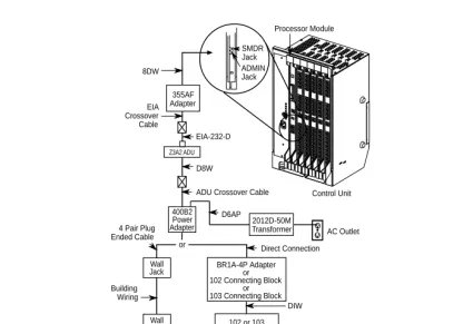
The PC should be connected to the lower port (labeled ADMIN) on the processor module. A PC with a modem can perform system programming remotely through the public network, or by connecting to a tip/ring extension jack (016 (T/R), 016 ETR programmed for T/R operation, or 008 OPT module) on the system. A built-in modem in the processor allows the PC and the system to communicate.
■ Extension Programming. This type of programming enables individual extension users and
system operators (except for Queued Call Console operators) to change their extension features to meet individual needs. For details about extension programming, see the appropriate user and operator guides.
■ Centralized Telephone Programming. This type of programming enables the System
Manager to program any feature that can be programmed by individual extension users or system operators. Some features can be programmed only in centralized telephone
Programming Basics
1-4 System Programming Console
1
System Programming Console
1The system programming console is a 4424LD+ or MLX-20L telephone connected to the system programming jack. When you begin system programming on a new system for the first time, the console must be connected to the first jack on the first 412 LS-ID-TDL or 024 TDL module if you are using a 4424 LD+ telephone, or to the first jack on the first 008 MLX module, 016 MLX module, or 408 GS/LS-ID-MLX module if you are using an MLX-20L telephone. The first jack on the first TDL or MLX module is factory set as the system programming jack and as an operator position. When you program for the first time, you can change the system programming jack to any one of the first five jacks on the first 412 LS-ID-TDL module or 024 TDL module, or on the first 008 MLX module or 408 GS/LS-ID-MLX module. This allows you to program without interfering with the operator’s call handling.
You can also have one or two Direct Station Selectors (DSSs) connected to the system programming console. Each DSS adds 50 extension buttons to the console, which facilitates assigning features to extensions. The DSS for the 4424LD+ console is the DSS 4450.
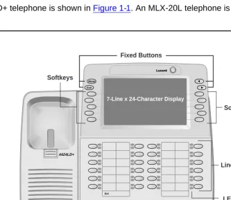
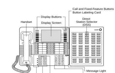
A 4424LD+ telephone is shown in Figure 1-1. An MLX-20L telephone is shown in Figure 1-2.
Figure 1-1. 4424LD+ Telephone
Spkr Redial
Mute Conf
Trnsfr
Hold
3 D E F
6 M N O
9 W X Y Z 2 A B C
5 J K L
8 T U V
0 1
4 G H I
7 P Q R S
Programming Basics
1-5 System Programming Console
1
Figure 1-2. MLX-20L Telephone
Console Components
1Table 1-1 describes the components that make up the 4424LD+ or MLX-20L Console. Refer to
Figure 1-1 and Figure 1-2 for the location of the components. Table 1-2 describes the components
that make up the DSS.
Table 1-1. 4424LD+ and MLX-20L Console Components Component Function
Desk Stand (not shown)
An adjustable stand on the console and the DSS allows a 20- or 30-degree viewing angle (optional on the 4424LD+ telephone).
Button Labeling Cards
Cards labeled with the number or feature assigned to each line button.
Contrast Control (not shown)
A sliding control at the top of the console, used to brighten or dim the display screen.
ABC DEF GHI JKL MNO PQRS TUV WXYZ
OPER
1 2 3
4 5 6
7 8 9
0 # * Direct Station Selector (DSS) Display Buttons Display Screen Handset Volume v v Feature HFAI Mute Speaker Hold Drop Conf Transfer Home Menu More Inspct 00 Message Light Volume Control
User Cards and Tray Fixed-Feature Buttons (8)
Dialpad
Call and Fixed-Feature Buttons Button Labeling Card
Programming Basics
1-6 System Programming Console
1
Fixed Feature Buttons
4424LD+ telephone fixed display buttons for most-used features:
Spkr (Speaker) for turning the speakerphone on and off.
Mute for turning the speakerphone’s microphone and, if applicable, the headset’s microphone on and off.
Trnsfr (Transfer) for sending a call to another telephone.
Conf for adding a line or extension to a conference call.
Redial for redialing the last number dialed from the telephone.
Hold for putting a call on hold.
MLX-20L telephone fixed display buttons for most-used features:
Feature for viewing the Feature screen and selecting features.
HFAI (Hands-Free Answer on Intercom) for answering voice-announced calls without the handset.
Mute for turning the speakerphone’s microphone on and off.
Speaker for talking on a call through the speakerphone without lifting the handset.
Transfer for sending a call to another telephone.
Conf for adding a line or extension to a conference call.
Drop for disconnecting an extension or line from a conference call.
Hold for putting a call on hold.
Dialpad Number pad for dialing telephone numbers.
Direct Station Selector (DSS) (not shown)
A device that adds extension buttons and other buttons to the console. See
Table 1-2.
Display Buttons Four fixed display buttons and 10 unlabeled buttons used to view the different screens and select names, features, and options from the display screen. See ‘‘Console Buttons’’ on page 1-8.
Display Screen Screen with a 7-line by 24-character display area that shows call information, features, prompts, date, and time.
Handset The hand-held part of the console you pick up, talk into, and listen from.
LEDs (Light-Emitting Diodes) The lights on the console that assist in checking feature status.
Line Buttons Buttons to make and receive calls; unlabeled buttons are programmable for one-step feature use. The 4424LD+ has 24 line buttons, and the MLX-20L has 20 line buttons.
Message Light A red light that signals a waiting message.
Table 1-1. 4424LD+ and MLX-20L Console Components — Continued
Programming Basics
1-7 System Programming Console
1
User Cards and Tray (MLX-20 only)
A slide-out drawer with erasable cards for noting telephone numbers and feature codes.
Volume Control A button for adjusting the volume of speaker, handset, headset, and ringer.
Table 1-2. Direct Station Selector (DSS) Components Component Function
Covers Removable plastic covers to protect the designation cards. The top cover protects the 50 DSS button labels. The lower cover fits over the fixed buttons.
DSS Designation Cards
Cards for labeling the extension or feature assigned to each button.
DSS Buttons Fifty buttons used for one-touch dialing of co-workers’ extensions to make or transfer calls. DSS buttons are also used to page co-workers over speakerphones, to park calls, and to handle outside calls.
Fixed Buttons Ten additional buttons, including Message Status, Direct Voice Mail (MLX DSS only), and three Page buttons. The five remaining buttons on the first DSS are not used. If a second DSS is connected to the console, the 10 buttons at the bottom of the second DSS are not used.
Fixed Message Status button used with fixed Page buttons to see which telephones have Message Lights on.
Fixed Page Buttons are three buttons used to select the pages of extensions that the 50 DSS buttons represent.
LEDs (Light-Emitting Diodes)
The lights that assist in checking feature status.
Table 1-1. 4424LD+ and MLX-20L Console Components — Continued
Programming Basics
1-8 System Programming Console
1
Console Buttons
1Use the 14 buttons located on either side of the 4424LD+ or MLX-20L console display area for system programming. These buttons are arranged in two columns of seven buttons, as shown in
Figure 1-3 and Figure 1-4. On the 4424LD+ console, three of the four fixed display buttons have
different labels than those on the MLX-20L console, although the same functionality is provided (see ‘‘Fixed Display Buttons” that follows).
Figure 1-3. 4424LD+ Display Buttons and Main Menu
Figure 1-4. MLX-20L Display Buttons and Main Menu
Fixed Display Buttons
1The top two buttons in each column have the same labels and functions regardless of the screen display. This type of button is called a fixed display button. Table 1-3 describes the functions of the fixed display buttons for the 4424LD+ and MLX-20L consoles.
Exit Menu
MENU MODE: Select Feature Press EXIT to Quit
Directory Messages Posted Msg Alarm Clock
Timer Ext Program Maintenance Sys Program
Home Menu
More Inspct
MENU MODE: Select Feature Press Home to Exit
Directory Messages Posted Msg Alarm Clock
Timer Ext Program
Programming Basics
1-9 System Programming Console
1
Unlabeled Display Buttons
1Use the five unlabeled display buttons on each side of the screen to select commands, options, or items on the screen. The functions of these buttons vary, based on the option you select.
If you are using WinSPM for system programming, the simulated 4424DL+ or MLX-20L console screen on your PC screen shows the function keys that correspond to the console screen selections. For example, to save an entry, you select Enter on the console or click in the emulation display on your PC. See Chapter 2, ‘‘Programming with WinSPM,” for details about using function keys and additional information about WinSPM.
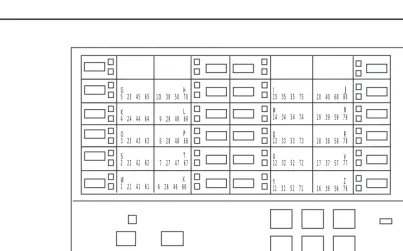
Console Overlay
1The programmable line buttons are on the main part of the console. There are 24 line buttons on the 4424 LD+; however, the four buttons on the top row are not used during system programming.
The MLX-20 console has 20 line buttons, but you can use the console overlay to program up to 28 line buttons on any extension through centralized telephone programming. Select Page 1 to access line buttons 1 through 20 and Page 2 to access line buttons 21 to 34. The top line of numbers next to each line button on the console overlay represents line buttons. See Figure 1-5
and Figure 1-6 that follow.
Appendix E shows the button diagrams for the telephones used in the system. Refer to this
appendix when programming buttons for other telephones.
Table 1-3. Fixed Display Buttons MLX-20L
Buttons
4424LD+
Buttons Function
Home Exit Return to normal call handling mode after you finish programming.
Menu Menu Display the Main menu shown in Figure 1-3.
More Display more items when a menu is continued on more than one screen, indicated by an angle bracket (>) on the upper right of the screen.
Inspct (Inspect) View a list of lines or extensions on which a feature is programmed or the settings for a feature. On the 4424LD+ console, an Inspect button must be programmed (programming code *778).
Programming Basics
1-10 System Programming Console
1
When labels or filenames are entered, the letters A through F are displayed on the console screen. Additional letters can be entered by using line buttons 1 through 20 to represent letters G through Z. These letters are also displayed on the top line of the console overlay.
Figure 1-5. 4424LD+ System Programming Console Overlay
G 5 25 45 65
K 4 24 44 64
O 3 23 43 63
S 2 22 42 62
W 1 21 41 61
1O 30 50 70 H
9 29 49 69 L
8 28 48 68 P
7 27 47 67 T
6 26 46 66 X
I 15 35 55 75
M 14 34 54 74
Q 13 33 53 73
U 12 32 52 72
Y 11 31 51 71
20 40 60 80 J
19 39 59 79 N
18 38 58 78R
17 37 57 77V
16 36 56 76 Z
Stop
Pause 4424LD+
Programming Basics
1-11 System Programming Console
1
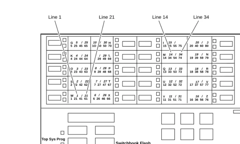
Figure 1-6. MLX-20L System Programming Console Overlay
The Top Sys Prog labeled function shown on the console overlay in Figure 1-6 does not appear on the 4424LD+ console overlay. The 4424LD+ does not provide a fixed HFAI (Hands Free Answer on Intercom) button for this feature; however, the HFAI feature can be programmed onto a line button on the 4424LD+ telephone and then used for system programming.
When programming lines/trunks, you can select a block of 20 lines/trunks as shown in Figure 1-7, and toggle the green or red LED associated with each line button on the console to program each line/trunk. The bottom line of numbers next to each line button on the console overlay represents the twenty lines/trunks associated with each line button (see Figure 1-6).
Figure 1-7. Selecting a Block of Lines/Trunks
OutTrunk Dial: For a single-line, go to:
Enter Trunks w/TouchTone
l
Single-Line Procedure.Lines 01-20 Entry Mode
Lines 21-40 For a block of lines, go to:
Lines 41-60
u
Block Procedure.Lines 61-80
Exit
G 5 25 45 65 K 4 24 44 64 O 3 23 43 63 S 2 22 42 62 W 1 21 41 61
1O 30 50 70 H
9 29 49 69 L
8 28 48 68 P
7 27 47 67 T
6 26 46 66 X
I 15 35 55 75 M 14 34 54 74
Q 13 33 53 73 U 12 32 52 72
Y 11 31 51 71
20 40 60 80 J
19 39 59 79N
18 38 58 78R
17 37 57 77V
16 36 56 76 Z
Top Sys Prog
Stop/Drop Entry
Pause Switchhook Flash
5 / 25
4 / 24
3 / 23
2 / 22
1 / 21 10 /30
9 /29
8 / 28
7 /27
6 / 26
15 20
14 / 34 19
13 /33 18
12 / 32 17
11 / 31 16
/ /
/
/
/
/
Programming Basics
1-12 Programming Procedures
1
Console and DSS Lights
1The red and green lights (LEDs) next to each of the 20 line buttons on the 4424LD+ and MLX-20L console show the status of the line/trunk options. LEDs on the DSS show the status of features programmed on extensions. See Appendix C, ‘‘LED Displays,” for more information.
Console Lights
1The green and red LEDs next to each button on the console display the status of the line/trunk option that is being programmed. For example, when you select Pools from the Lines Trunks menu, the red LED is off if the selected line is not in a pool and on if the line is in a pool. Appendix
C, ‘‘LED Displays,” provides a table that shows the default LED status for line/trunk options.
DSS Lights
1The lights on the DSS (if one is attached to the console) show the status of features being programmed on the extensions. When you select a feature from a menu, the red LED next to the DSS button is on, off, or flashing, depending on whether the feature is already programmed on the corresponding extension. For example, when you select TollRestrict from the Restrictions menu, the red LED next to the DSS button lights for each toll-restricted extension. Appendix C,
‘‘LED Displays” provides a table that shows the default DSS status of LEDs for system features.
Programming Procedures
1The programming procedures provide step-by-step instructions for programming the system. This section details how to make the best use of the programming procedures.
Procedure Organization
1The programming procedures in Chapter 3, ‘‘Programming Procedures,” are organized into logical groups. The programming procedures associated with a specific aspect of the system are grouped together under one heading. For example, to assign network services for PRI, you would go to the section titled ‘‘PRI Facilities’’ and then locate the network services procedure. For quick reference,
see ‘‘System Programming Hierarchy’’ on page 1-19 for a list of procedures based on the menu
Programming Basics
1-13 Programming Procedures
1
Procedure Contents
1Each procedure begins with a general description of the feature, followed by a summary of programming information that includes the items listed below:
Programming Screens
1There are three types of system programming screens:
■ Information Screens. To view what is currently programmed on the system.
■ Menu selection screens. To select options from a menu.
■ Data entry screens. To enter values or to identify a specific extension or line/trunk you want
to program.
Figure 1-8 shows a sample information screen. When you select SysProgram from the Main
menu screen (shown in Figure 1-3 on page 1-8), the screen shown in Figure 1-8 appears with system setup information.
Programmable by Indicates who has permission to use the procedure.
Mode Specifies which system mode supports the procedure: Key, Hybrid/PBX, Behind Switch, or a combination.
Idle condition Specifies the idle state required before the procedure can be performed. Planning form Indicates the planning forms that provide information for the procedure. Factory setting Shows the factory settings, if any, for equipment or features affected by
the procedure.
Valid entries Specifies the characters, numbers, or values accepted during data entry. Inspect Specifies whether or not the feature status can be verified using the
Inspect feature.
Copy option Indicates whether or not the feature can be copied to another system component once it has been programmed.
Programming Basics
1-14 Programming Procedures
1
Figure 1-8. Information Screen
You cannot make changes on an information screen. Select Back (or click in the PC emulation display) to continue to the next screen in the procedure.
Figure 1-9 shows a sample menu selection screen.
Figure 1-9. Menu Selection Screen
A menu selection screen prompts you to select one of the available options. The screen title is the first line on all screens. The second line contains a system prompt or instruction. The remaining lines of text vary, based on the selected option.
An angle bracket (>) appears in the upper right corner of menu selection screens that have additional option screens. Press or More (or click in the PC emulation display) to see the additional screens; continue to press or click these buttons to move through the screens and return to the original screen. Figure 1-10 shows a sample data entry screen.
System Set-up Your system information appears in
Review and Exit place of the x’s.
Size: xxxx
Type: xxxx
Operator: xxxx xxxx xxxx xxxx xxxx xxxx
Back
System Programming: > Screen title and More indicator (>)
Make a Selection Prompt
System Extensions Options List
SysRenumber Options
Operator Tables
LinesTrunks AuxEquip
Programming Basics
1-15 Programming Procedures
1
Figure 1-10. Data Entry Screen
A data entry screen prompts you to enter specific data or to make specific choices. Data to be entered will be displayed with n’s in the text. When n’s appear on the data entry screen they indicate data currently programmed for the feature. An exception is the slot/port number which is displayed as sspp to distinguish the 2-digit slot number from the 2-digit port number. Slot is the slot number in the carrier and port is the port number on the module.
Many screens show data entered on a previous screen, such as an extension or trunk number. Within the programming procedures, this type of variable information is shown with x’s.
When information to be entered varies in the number of digits required (for example, a telephone number that can range from 7 to 20 digits), the data may be displayed as an uppercase X or N.
Data entry screens may also contain menu selections. Instead of entering data from the dialpad, you select options on the screen, such as Yes or No, to enable or disable a feature. To select this type of option, press either the unlabeled display button next to the option name, or the function key that corresponds to the option name. Then your selection is highlighted. To program or save the highlighted selection, press the unlabeled display button next to Enter (or click in the PC emulation display).
Assign Lines/Trunks: Selected Option
Enter extension Prompt
Data Entry Area
Backspace
Back Enter
Programming Basics
1-16 Programming Procedures
1
Verifying Data Entry
1You can use the Inspect feature to view the entries you save.
The Inspect button is fixed on an MLX-20L. To use the Inspect feature on a 4424LD+ telephone, you must program a line button with the Inspect feature (refer to Feature Reference for
programming the Inspect button.
An example of how to use the Inspect feature begins with Figure 1-11. The figure shows a data entry screen with the adjunct extension number of an MLX port.
Figure 1-11. Inspect Example
After you enter and save 7108, you can enter and save another extension; the extensions you enter appear one at a time in the screen, as you enter and save them. However, if you press the Inspect button ( in the PC emulation display), all extension numbers that you have
programmed in this data entry screen appear. For example, if you entered 7108, 7109, and 7110, when you press the Inspect button, all the extension numbers appear as shown in the sample Inspect screen in Figure 1-12.
Figure 1-12. Sample Inspect Screen
Whenever you want to return to the previous screen, select Back ( in the PC emulation display).
2B Data\Video: > Selected Option
Enter adjunct extension number of an MLX port
Prompt
7108 Extension Entered
Delete
Backspace
Back Enter
2B Data\Video: >
7108 7109 7110 Inspect Data Displayed
Programming Basics
1-17 Programming Procedures
1
The Inspect feature also allows you to check a value that has already been programmed for a feature. This is helpful when you are changing or modifying features. You can also use it when you program sequential extensions or lines to verify the last number programmed. See the Feature Reference for details about the Inspect feature.
Saving Entries and Moving among Screens
1At the bottom of each screen, one or more screen keys may appear representing functions that allow you to change your entry, save your entry, or return to a previous screen. Various
combinations of these screen keys appear on each programming screen. Figure 1-13 shows the QCC Priority screen with a typical display of screen keys.
Figure 1-13. Screen Keys
The PC keys that correspond to the screen key selections are shown here for quick reference. These PC keys do not appear on the console display screen. Table 1-4 contains details on the use of the screen keys.
QCC Pri