Remote Inter-Chip Power Analysis Side-Channel
Attacks at Board-Level
Falk Schellenberg
∗‡, Dennis R.E. Gnad
†‡, Amir Moradi
∗, and Mehdi B. Tahoori
† ∗Horst Görtz Institute for IT Security, Ruhr-Universität Bochum, Germany†Institute of Computer Engineering, Karlsruhe Institute of Technology (KIT), Karlsruhe, Germany
∗{falk.schellenberg, amir.moradi}@rub.de†{dennis.gnad, mehdi.tahoori}@kit.edu ‡These authors contributed equally to this work.
Abstract—The current practice in board-level integration is to incorporate chips and components from numerous vendors. A fully trusted supply chain for all used components and chipsets is an important, yet extremely difficult to achieve, prerequisite to validate a complete board-level system for safe and secure operation. An increasing risk is that most chips nowadays run software or firmware, typically updated throughout the system lifetime, making it practically impossible to validate the full system at every given point in the manufacturing, integration and operational life cycle. This risk is elevated in devices that run 3rd party firmware. In this paper we show that an FPGA used as a common accelerator in various boards can be reprogrammed by software to introduce a sensor, suitable as a remote power analysis side-channel attack vector at the board-level. We show successful power analysis attacks from one FPGA on the board to another chip implementing RSA and AES cryptographic modules. Since the sensor is only mapped through firmware, this threat is very hard to detect, because data can be exfiltrated without requiring inter-chip communication between victim and attacker. Our results also prove the potential vulnerability in which any untrusted chip on the board can launch such attacks on the remaining system.
I. INTRODUCTION
Board-level integration is a complex engineering challenge in which many components from various vendors, geographi-cally scattered in the world, are integrated into a single Printed Circuit Board (PCB) to form a bigger electronic system [1]. To verify the system, a fully trusted supply chain is assumed and important for system safety and security [2]. Leaving aside the difficulties of establishing such a trusted supply chain, the chips in such larger systems are based on their own software or firmware images that might be supplied independently from the chip itself. Even after manufacturing and integration, some chips are updated throughout their operational lifetime, while the system is in use. In an existing chain of trust, these risks are mitigated by cryptographically signed firmware updates [3], as they are supplied by manufacturers of smart TVs, networking equipment, routers and any sort of IoT or home appliances, just to name a few.
These chains of trust can be broken in many cases. First of all, outdated cryptography might be used for trusted firmware upgrades that is easy to break due to being legacy or is not protected against all types of attacks [4], [5]. In other situations, the manufacturer secret keys can be extracted or get
leaked, or certain devices in the system might not support the mechanisms required for trusted firmware updates at all [6].
Full system integrity is also hard to guarantee if software or firmware from a 3rd party is run on any chip in the system. In these situations, malicious applications can be introduced accidentally, for instance by executing any content from the Internet, which might just be javascript on a website [7]. In those cases, it is of high importance to provide proper isolation of individual system components, typically handled at the logical level (cf. javascript sandboxes). For instance, in the recent Meltdown and Spectre [8], [9] attacks it has been shown that such isolations can be broken, and a user can escalate their privileges and gain superuser access.
Particularly FPGAs are increasingly used as accelerators in many systems, ranging from Cloud-computing appliances [10], [11], [12] to getting integrated in complex SoC devices. Very small FPGAs are often inserted as glue-logic as a translation layer between other existing devices. What all FPGAs in these use cases have in common is that they are part of a bigger system, probably sharing the power supply with other components, i.e. even as a PCIe device.
It has also been recently shown that a chip containing FPGA fabric can be used to implement sensors that are sufficient for
remotepower analysis side-channel attacks within the FPGA [13], or CPUs in the same SoC [14]. The threat from power analysis attacks was previously assumed to require an attacker with physical access.
In this paper, we escalate the risk of remote power analysis attacks from the chip to the board-level, affecting much more potential components of an entire system. We show that even through multiple levels of a power distribution network, in which capacitive, inductive, and resistive effects persist, sufficient side-channel information can be extracted to attack a cryptographic module in another chip placed on the same board.
Contributions: Our main contribution is a first proof of a board-level Side-Channel Analysis (SCA) attack from one chip to another, based on software-reconfigurable firmware. In short, the contributions of this work can be summarized as follows:
• Depending on the system configuration, the attack can be
introduced remotely and in software,
• We provide two case studies on an inter-chip attack on AES and RSA, proving the high risk of this threat.
• If local access to a system is given only for a short time, the attack can infect a system in a covert way, because no external or dedicated measurement equipment is required.
Outline: The rest of the paper is organized as follows: Section II elaborates our adversary model in more detail and explains some background knowledge on board-level supplies and power-analysis side channels. In Section III, our experi-mental setup will be explained, followed by our results given in Section IV. Finally, we conclude the paper in Section V.
II. PRELIMINARIES
A. Adversary Model and Threat Analysis
Secure system design typically involves a trusted computing architecture in which adversaries are allowed to manipulate any chip outside of a Trusted Computing Base (TCB) in order to attack it by any means possible [15]. The TCB is achieved through isolationandattestation. Isolation is implemented by access control to and from secure enclaves, and attestation proves the integrity of system components within the enclaved TCB, for example through protecting firmware images against unauthorized modification. Because most trusted computing models do not consider the electrical level, a famous archi-tecture for SoCs, ARM TrustZone, was shown vulnerable to fault attacks through power management [16].
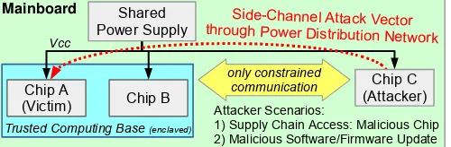
In this paper we assume related threats, elevated to the board-integration level. In Fig. 1 we show an adversary sce-nario on a PCB with multiple chips, supplied by the same power supply. Two of them (Chip A and B) are within a secure enclaved TCB. Chips outside of the TCB can be accessed locally or remotely by a 3rd party entity, which can be an attacker in Chip C. The goal of the adversary is to gather secret information from a victim component within the secure enclave, for instance a cryptographic accelerator in Chip A.
There are two possible cases for the adversarial access to Chip C outside of the TCB:
1) Chip C is provided by an attacker which can access the supply chain to introduce a malicious chip into the system.
2) Chip C is a benign chip by design but can run different software or firmware (for instance, a cloud accelerator).
Mainboard
Chip B
Side-Channel Attack Vector through Power Distribution Network Shared
Power Supply
only constrained communication Chip A
(Victim) Vcc
Chip C (Attacker)
Trusted Computing Base (enclaved)
Attacker Scenarios:
1) Supply Chain Access: Malicious Chip 2) Malicious Software/Firmware Update
Fig. 1: Scenario of a shared power supply leading to a risk of side-channel attacks. In this example Chip C tries to deduce information from the power supply on Chip A.
The adversary is restricted to reprogram the single device Chip C, which is logically isolated from the enclave, but shares the same power supply with the victim in the enclave.
By means of measurements on the power supply, Chip C can thus attack Chip A in the enclave, even when a TCB was logically established. After the attack, the adversary with access to Chip C can use any type of communication channel to transmit the side-channel information remotely and analyze it, to extract secret keys from the victim system. If no proper communication channel exists, covert channels can be used to transmit this information [17], [18], [19].
B. Power Delivery at Board-Level
Each modern electronic system requires at least one power supply, integrated on the PCB. In total, a more complex Power Distribution Network (PDN) starts at a voltage regulator as the main board-level power supply at a higher voltage, e.g. 12V. The power is hierarchically distributed across the board and can go through multiple stages of lower voltage regulators. These regulators supply a range of chips on the board. Finally, inside the chip, a network similar to a mesh supplies all the individual transistors. On all of these levels, resistive (R), capacitive (C) and inductive (L) components are integrated either by design or as parasitic, i.e. unwanted, part of the whole network [20].
During the operation of a circuit, transistors are switching dependent on the data being processed. Different switching activities lead to fluctuations in power consumption (P =
V ·I), resulting in a change of the required current. That change, in effect, causes voltage fluctuations on the power rails, dependent on inductive and resistive elements in the chip
Vdrop=L·dI/dt+IR, stabilized by capacitors.
Thus, anything connected to at least the same voltage regulator is able to see the voltage fluctuations, and can potentially use it for power analysis side-channel attacks, if sufficiently precise sensors are present [21].
C. Power Analysis Side-Channel Attacks
Side-channel attacks exploit non-intentional information channels such as the power consumption of a device to deduce secret data. If the device computes some cryptographic function, an adversary usually targets the used secret key hidden in the device.
D. Voltage Drop Sensors
To measure a voltage drop on board-level, malicious chips could use their ADC connected to the power rails as a sensor to sense voltage fluctuations from other chips. However, this would be an obvious issue at manufacturing time. Thus, it is more critical when software can re-use existing hardware as a sensor that is sufficient to sense voltage drop, or maliciously supplied chips that connect their power supply to a hidden ADC on the inside.
Since FPGAs provide sufficient flexibility through software reconfiguration, previous works have shown how to sense voltage fluctuations in the nanosecond scale [23], just by the re-use of FPGA primitives. These sensors are based on measuring the signal propagation delays, in which a signal propagates through a long range of buffers. Then, the sensor measures how far the signal can propagate in a given clock cycle. In succession, they were also used to analyze workload-dependent voltage transients within an FPGA [22]. The sensor is explained with the help of Fig. 2. Here, the clock signal is connected as the entry-point of the line of buffers, and at the same time is used to sample how far it can propagate through the line. Finally, in each clock cycle, a sample of buffer propagation is measured, which (besides negligible thermal variations) proportionally shows the voltage level supplying the transistors used in the buffers. A similar design was used in [13] for power analysis attacks within the same chip, i.e., from one region to another within the same FPGA.
III. EXPERIMENTALSETUP
In this section we explain our experimental setup in generic and then go on to briefly explain the victim and attacker designs. Previous work has shown that SCA attacks are possible within a chip [13]. Beyond that, we prove that such attacks can be performed inter-chip on the board-level. To this end, we use the well-known SAKURA-G board [24] that was designed for external side-channel analysis research, e.g., by offering measurement points for traditional oscilloscopes.
The main reason for using the SAKURA-G in our experi-ments is that it contains two FPGAs on a single board, where both can be freely programmed. It contains two Spartan-6 FPGAs: a small auxiliary FPGA (XC6SLX9), and a larger
mainFPGA (XC6SLX75). We ran different configurations for the capacitors between VDD and GND, i.e., the unaltered default configuration of the SAKURA-G and with all small-value capacitors close to the FPGAs removed. In any case, we inserted a small bridge so that the core voltage of the
TDC register [0 .. N] Clock
... ...
...
Latches Initial Delay Observable Delay Line
Delay Line Out
1 1 0 0
`110..00'
0
Range of Latches
enable
Fig. 2: Principle of the TDC Sensor as shown in [22].
SAKURA-G Board
Main FPGA (Attacker) TDC
Sensor UART Tx
Auxiliary FPGA (Victim) Shared
Power Supply
Plaintext
Ciphertext PC Voltage Trace
Plaintext UART Rx
UART Tx Power Supply
Side-Channel
Victim Module SecretKey
Fig. 3: Experimental setup showing the SAKURA-G Board connected to our measure-ment PC.
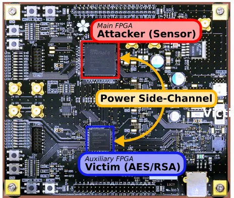
Fig. 4: Setup showing the configuration of the two FPGAs on the SAKURA-G board. The sensor to attack is in the main FPGA, while the cryptographic module (AES or RSA) runs on the auxiliary FPGA.
main FPGA is provided by the same power supply as for the auxiliary FPGA. This modification does resemble more typical industrial boards, in which power supplies of the same voltage level are shared for efficiency reasons.
Fig. 3 gives an overview of this experimental setup. The auxiliary FPGA receives plaintexts from the PC and encrypts them with an internal secret key, sending the ciphertext back to the PC. The main FPGA uses a sensor and transfers the sensor data to the PC. For the ease of experimentation, the main FPGA also receives a trigger signal whenever the auxiliary FPGA starts an encryption. In a real-world scenario, an encryption might be triggered externally (by the PC) or the traces can be realigned using existing work. On the PC, we then launch simple and differential power analysis attacks on the recorded sensor data. Fig. 4 shows the two FPGAs on the SAKURA-G Board and their respective roles in our setup.
s4 s5 s6 s7
s8 s9 s10 s11
s12 s13 s14 s15 Sbox
Sbox
Sbox
Sbox s0 s1 s2 s3 RoundKey
Fig. 5: Architecture of the underlying AES encryption core (ShiftRows and KeySchedule not shown), as shown in [13]
A. AES victim module
The AES module we use in this paper as a case study is a simple implementation that is not side-channel protected and follows the design principle that was explained in [13], to be comparable. On systems that are just remotely-accessed, considering such an unprotected module is a valid assumption, since the threat of power analysis side-channel attacks is not considered in remote adversary models. We use a 128-bit AES implementation that is based on a 32-bit datapath. The 128-bit plaintext is XORed with the first roundkey and then loaded in the state register si. Each cipher round requires 5 cycles in this implementation. In each subsequent cipher round, the respective operations for AES, Byte Substitution in the Sbox, ShiftRows (not shown since it is only re-wiring), MixColumn and AddRoundKey are performed. In total the encryption takes 50 clock cycles and the resulting ciphertext can be acquired from the state registers. In the used auxiliary FPGA (Spartan-6 XC6SLX9), the resource utilization is minimal, but percentage-wise higher compared to what was reported in [13], since the FPGA we use is smaller. The AES module is running at 24 MHz.
B. RSA victim module
We implemented RSA using a straightforward right-to-left binary exponentiation [25], i.e., following the same principles as the one used in [14] for the sake of comparability. The pseudo-code is given in Alg. 1. In each iteration step of the exponentiation, a squaring is executed. If the current (secret) bit of the exponent is set, the squared term of the previous step is multiplied to the register storing the result.
Like [14], if a specific step of the algorithm does not require a multiplication, one of the inputs is set to 1, i.e., calculating the identity function. Thus, in order to retrieve the secret exponent, the adversary tries to identify whether or not an actual multiplication took place for each of the steps in the binary exponentiation.
Both squaring and multiplication are implemented as sep-arate modules using dedicated multiplication cores with in-tegrated modular reduction. The multipliers itself operate on the shift-and-add principle: In each clock cycle, one operand is multiplied by two (left shift) and reduced. If the current bit of the other operand is set, the shifted term gets added to the result register.
The limited resources of our auxiliary FPGA only sufficed for a rather small key-size of 224-bit, running at 24 MHz.
Algorithm 1 Right-to-left binary exponentiation (cf. 14.76 of [25])
Input: Message x, Exponent e, Modulus N
Output: xe modn 1: A←1,S←x
2: while e6= 0do 3: if eis oddthen 4: A←A·S modN
5: else
6: A←A·1 modN
7: end if 8: e← be/2c
9: S←S·S modN
10: end while 11: Return(A)
However, we stress that RSA implementations with a larger key size are usually much easier to attack using Simple Power Analysis (SPA) than smaller ones. This stems from the fact that because of the larger operand sizes, the multiplication cores require more cycles while consuming more power as well.
For our proof-of-concept implementation, we have 224 steps of the binary exponentiation, each requiring 224 clock cycles for the squaring and the multiplication running in parallel. Thus, for each step we have 224 clock cycles for which we have to decide whether a multiplication is taking place or not. Considering for example an RSA with a 4096-bit key size, the computation time is increased to 4096 cycles likewise.
C. Sensor Attacker Module
We reproduced the previously explained and known TDC sensor to measure a fraction of the power supply noise of the system [13]. Using this type of sensor, internal side-channel analysis was also possible in our tested systems. However, for the sake of brevity we only look into measuring inter-chip attacks. We also made sure to run our sensor in the same frequencies as in the previous work of 24, 48, 72, and 96 MHz. As we also use the same type of evaluation board and FPGAs, this should allow comparable results. Furthermore, these frequencies are easily created based on the board-level 48 MHz crystal oscillator.
We transmit our data through UART in our experimental setup. In a real design other communication channels might be required. Thus, part of the key recovery algorithm itself could even be performed on the FPGA, to transmit the data in a more compressed format later on. If the compromised chip has no access to communication devices, it might need to send information through one of the numerous possible covert channels that previous works have explored [17], [18], [19].
IV. RESULTS
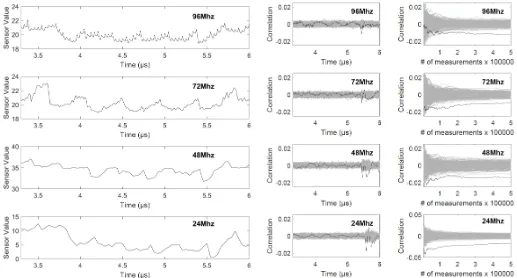
Fig. 6: Averaged traces measured during AES using the TDC sensors at different sampling frequencies.
the TDC sensor captured the inter-chip voltage drop through its supply pin on the main FPGA.
A. Attack on AES
As discussed in [13], the TDC sensors incorporate an in-verse relation between the sampling frequency and the amount of variation that is captured. Hence, we chose to run the attack for different sampling frequencies as well. Fig. 6 depicts the exemplary traces, for each sampling frequency averaged over 1000 measurements. The AES encryption is taking place approximately between 3.6 and 5.7 µs.
Similar to [13], we run a textbook CPA attack, using the ciphertexts to predict the state before the last Sbox operation based on key hypothesis. Fig. 7 depicts the corresponding re-sults for the attacks: For each sensor frequency, the correlation after 500 000 traces is plotted on the left and the progress of the maximum of the correlation on the right. The curve belonging to the correct key candidate is marked in black. Indeed, the attack succeeds for all tested sampling frequencies, yet at a large deviation relation to the amount of required traces. For the 96 MHz sensor, the correct key candidate is starting to stand out after approximately 200 000 processed traces. Considering the 24 MHz sensor instead, the correct key candidate is visible immediately after around 20 000 traces.
Comparing our results to the ones reported in [13] for sensor and target implemented within the same FPGA, we require more traces by a factor of 40, considering the respective best attacks. It should be noted that none of the smallest-value capacitors between VDD and GND were put in place
Fig. 7: CPA attack on AES: Results to estimate the sensor quality at different sampling rates, with a board when all relevant capacitors are removed. Each row shows the correlation using 500 000 traces (left) and the progressive curves over the number of traces (right). The correct key hypothesis is marked in black. Time samples refer to the individual samples captured at the respective sampling rate.
Fig. 8: CPA attack on AES: Progressive curves over the number of traces with a board when all relevant capacitors are removed (left) and with the default capacitor configuration (right), both sampled at 24 MHz. The correct key hypothesis is marked in black. Time samples refer to the individual samples captured at the respective sampling rate.
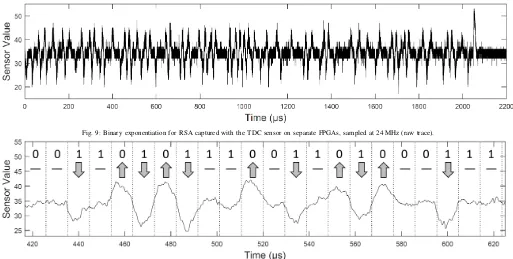
Fig. 9: Binary exponentiation for RSA captured with the TDC sensor on separate FPGAs, sampled at 24 MHz (raw trace).
Fig. 10: Detail of the binary exponentiation captured with the TDC sensor after applying a 900 kHz low-pass filter. Dotted lines mark the time-span of an individual step in the binary exponentiation. Arrows indicated whether the state of the multiplication module changed (on to off: arrow upwards, off to on: arrow downwards, and no change: dash). The bits above are a part of the (correctly) recovered secret exponent according to this classification.
B. Attack on RSA
Based on the results for AES, we chose to measure the RSA core using a sampling rate of 24 MHz. As before, both FPGAs share a power supply and all capacitors are in place. The RSA is running at 24 MHz. Thus, we require at least 50 176 cycles to capture the whole binary exponentiation (224 clock cycles for each of the 224 steps). Fig. 9 depicts the raw trace with an already visible variation over a time span of approximately 2100 µs.
We recall that the adversary’s goal is to recover the secret exponent by identifying whether the multiplication took place or not. Every time a multiplication is performed (in parallel to a squaring), the circuit consumes more power. Fig. 10 depicts a detailed view after applying a low pass filter with a cut-off frequency of 900 kHz. Instead of simply capturing the increased power consumption during the multiplication, we can observe that the TDC sensor receives a differential signal of the encryption. Thus, we have to consider three different cases how the conditional multiplication in the binary exponentiation will affect the TDC sensor:
• If the multiplication module is switched from the off-state (factor of1applied to an input) to the enabled-state, the voltage will briefly drop until the power supply is compensated for the increased current. The voltage drop will slow down the signal in the TDC sensor, leading to a negative peak in the trace. An arrow pointing downwards indicates this case is Fig. 10.
• In case the multiplication is switched from the on-state to the off-state, i.e., the FPGA suddenly consuming less
power, the voltage overshoots briefly until compensated. This leads to a positive peak in the trace due to the accelerated sensor. This case is marked using an arrow pointing upwards. Also note the very large positive peak at the end of the exponentiation in Fig. 9, indicating that both the multiplier and the squaring module got deactivated.
• If the state of the multiplication does not change, i.e., either staying enabled or staying off, the power consump-tion remains identical. Thus, the voltage level is constant, causing a steady sensor value. This is indicated by a dash. These three cases are marked in the magnified view of Fig. 10. Indeed, the secret exponent can be read out easily even though the RSA and the TDC sensor are implemented on separate FPGAs sharing the same source of supply voltage.
C. Discussion
Our results prove that board-level power analysis side-channel attack threats exist, even in the presence of decoupling capacitors. Of course, same or even better results can be achieved when adding a dedicated ADC directly to the power rails, but obviously not without raising questions of its use. Instead, a seemingly disconnected FPGA would not raise any alarm even in a fully trusted supply chain. The malicious behavior can be enabled later on by a firmware to measure the supply voltage with the sensors.
internal ADC connected to the shared power supply as a power analysis attack vector. The same is true for any other chip on the board that can be used as a measurement device through maliciously altered firmware. An increasing number of sensors are integrated into all kinds of chips for increased reliability and monitoring purposes, even for voltage fluctuations [26], [27], elevating the risk of maliciously measuring them for power analysis attacks. In a system where only remote access is considered to be an attack vector, integrated cryptographic accelerators are often not protected against power analysis side-channels (i.e., only timing side-channels are avoided). Such systems could thus be attacked remotely if proper electrical isolation on the board integration level does not exist.
V. CONCLUSION
In this paper we show the feasibility of launching remote power analysis attacks on a full board, in which multiple trusted and untrusted chips share the same power supply. Based on an exemplary FPGA, we show the high risk in-volved in integrating chips on a board whose firmware or configuration is unknown at the time of board-integration. We integrate sensors that are known to measure the voltage fluctuations inside FPGA fabric and prove that they can also capture a fraction of the external inter-chip voltage drop. Using this mechanism, anychip next to the FPGA can be analyzed by power side-channel analysis attacks. We prove that this mechanism can lead to a successful key-recovery attack on an AES and an RSA core in a chip neighboring to the FPGA without any logical connections.
We should emphasize that the attack presented here is not limited to FPGAs, which only serve as a case study in this paper. Other untrusted chips, through untrusted manufacturing or untrusted firmware updates in the field, might also be able to measure such voltage fluctuations from a neighboring chip, e.g. using voltage monitors that are integrated for reliability reasons, but are re-programmable to serve other purposes. Thus, this paper gives a warning sign to all board-integrators that proper isolation is also required on the electrical level, as even a remote attacker might get hold of sufficient sensors for inter-chip board-level power analysis attacks.
REFERENCES
[1] R. Turner. System-level verification – a comparison of approaches. InInternational Workshop on Rapid System Prototyping, pages 154–159, Jul 1999.
[2] K. Chatterjee and D. Das. Semiconductor Manufacturers’ Efforts to Improve Trust in the Electronic Part Supply Chain. IEEE Transactions on Components and Packaging Technologies, 30(3):547–549, Sept 2007.
[3] Sompong P Olarig and Michael F Angelo. Method for the secure remote flashing of a BIOS memory, December 28 1999. US Patent 6,009,524.
[4] Amir Moradi, Markus Kasper, and Christof Paar. On the Portability of Side-Channel Attacks - An Analysis of the Xilinx Virtex 4, Virtex 5, and Spartan 6 Bitstream Encryption Mechanism. Cryptology ePrint Archive, Report 2011/391, 2011. https://eprint.iacr.org/2011/391.
[5] E. Ronen, A. Shamir, A. O. Weingarten, and C. O’Flynn. IoT Goes Nuclear: Creating a ZigBee Chain Reaction. InSymposium on Security and Privacy (S&P), pages 195–212, May 2017.
[6] James Hendricks and Leendert van Doorn. Secure Bootstrap is Not Enough: Shoring Up the Trusted Computing Base. InSIGOPS European Workshop. ACM, 2004.
[7] Daniel Gruss, Clémentine Maurice, and Stefan Mangard. Rowhammer.js: A Remote Software-Induced Fault Attack in JavaScript. In Detection of Intrusions and Malware, and Vulnerability Assessment, pages 300–321. Springer International, 2016.
[8] Moritz Lipp, Michael Schwarz, Daniel Gruss, et al. Meltdown. arXiv preprint arXiv:1801.01207, 2018.
[9] Paul Kocher, Daniel Genkin, Daniel Gruss, et al. Spectre Attacks: Exploiting Speculative Execution.arXiv preprint arXiv:1801.01203, 2018.
[10] Ken Eguro and Ramarathnam Venkatesan. FPGAs for trusted cloud computing. In
International Conference on Field Programmable Logic and Applications (FPL), pages 63–70. IEEE, 2012.
[11] Stuart Byma, J Gregory Steffan, Hadi Bannazadeh, Alberto Leon Garcia, and Paul Chow. FPGAs in the Cloud: Booting Virtualized Hardware Accelerators with Openstack. InInternational Symposium on Field-Programmable Custom Computing Machines (FCCM), pages 109–116. IEEE, 2014.
[12] Suhaib A. Fahmy, Kizheppatt Vipin, and Shanker Shreejith. Virtualized FPGA Accelerators for Efficient Cloud Computing. InCloudCom, pages 430–435. IEEE, 2015.
[13] F. Schellenberg, D.R.E. Gnad, A. Moradi, and M. B. Tahoori. An Inside Job: Remote Power Analysis Attacks on FPGAs. InDesign, Automation & Test in Europe (DATE), March 2018.
[14] Mark Zhao and G Edward Suh. FPGA-Based Remote Power Side-Channel Attacks. InSymposium on Security and Privacy (S&P), page 0. IEEE, May 2018. [15] P. Maene, J. Götzfried, R. de Clercq, et al. Hardware-Based Trusted Computing
Architectures for Isolation and Attestation. IEEE Transactions on Computers, 67(3):361–374, March 2018.
[16] Adrian Tang, Simha Sethumadhavan, and Salvatore Stolfo. CLKSCREW: Exposing the Perils of Security-Oblivious Energy Management. In USENIX Security Symposium, 2017.
[17] Markus G. Kuhn and Ross J. Anderson. Soft Tempest: Hidden Data Transmission Using Electromagnetic Emanations. InInformation Hiding, volume 1525 ofLecture Notes in Computer Science, pages 124–142. Springer, 1998.
[18] Ramya Jayaram Masti, Devendra Rai, Aanjhan Ranganathan, et al. Thermal Covert Channels on Multi-core Platforms. InUSENIX Security Symposium, pages 865– 880. USENIX Association, 2015.
[19] John C. Wray. An Analysis of Covert Timing Channels. InIEEE Symposium on Security and Privacy, pages 2–7, 1991.
[20] Karim Arabi, Resve Saleh, and Xiongfei Meng. Power Supply Noise in SoCs: Metrics, Management, and Measurement.Des. Test. Comput., 24(3):236–244, 2007. [21] Paul C. Kocher, Joshua Jaffe, and Benjamin Jun. Differential Power Analysis. In
CRYPTO, volume 1666 ofLNCS, pages 388–397. Springer, 1999.
[22] Dennis R. E. Gnad, Fabian Oboril, Saman Kiamehr, and Mehdi Baradaran Tahoori. Analysis of transient voltage fluctuations in FPGAs. InInternational Conference on Field-Programmable Technology (FPT), pages 12–19. IEEE, 2016.
[23] Kenneth M. Zick, Meeta Srivastav, Wei Zhang, and Matthew French. Sensing Nanosecond-scale Voltage Attacks and Natural Transients in FPGAs. In Interna-tional Symposium on Field Programmable Gate Arrays (FPGA), pages 101–104. ACM, 2013.
[24] Side-channel AttacK User Reference Architecture. http://satoh.cs.uec.ac.jp/ SAKURA/index.html.
[25] Alfred Menezes, Paul C. van Oorschot, and Scott A. Vanstone. Handbook of Applied Cryptography. CRC Press, 1996.
[26] A. Drake, R. Senger, H. Deogun, et al. A Distributed Critical-Path Timing Monitor for a 65nm High-Performance Microprocessor. InIEEE International Solid-State Circuits Conference (ISSCC), pages 398–399, Feb 2007.
![Fig. 5: Architecture of the underlying AES encryption core (ShiftRows and KeySchedulenot shown), as shown in [13]](https://thumb-us.123doks.com/thumbv2/123dok_us/7973993.1322302/4.612.55.294.53.132/fig-architecture-underlying-encryption-shiftrows-keyschedulenot-shown-shown.webp)