IMPROVING THE CAPACITY OF THE TEXTILE
DESIGNER TO CREATE COMPOUND STRUCTURES
FABRIC USING COMPUTER SOFTWARE (WEAVE
EDITOR)
Gamal Mohamed Radwan
Assistant Professor in Spinning, Weaving and Knitting Dept, Faculty of Applied Arts,
Helwan University
ABSTRACT
The program (weave editor) is a branch software from Ned Graphic program which helps the designer to build
compound fabric structures easily, where the role of the designer to propose an interlacement between warp
and weft thread while the program collect the fabric weave and calculation could also see the cross sector and
can also show simulation to the fabric structures after adding color threads for warp and weft and its count and
quality. when using the composite method to draw textile weaves than innovative designer capabilities through
easy draw and group it and change them and provide substitutes. This method enables the textile designer to
understand how to build textile weaves in case of multiplicity of wefts, and reach the largest possible number of
textile weaves both appear individually or in multiple ways to mix them.
In this search we will explore method of work of the Program and its application on some fabric structures and
then use the program to draw a total of compound fabric structures
.
I. INTRODUCTION
Fabric structures effect on functional and aesthetical sides of upholstery fabrics ,so the competition is difficult
locally and internationally and innovation and distinctiveness become the only to stay in the competition, also
the compound fabric structures is the most widespread in the upholstery fabrics, which will enable the designer
to get many of the color effects and different textures which it has become the first influential not only on the
functional characteristics of the product, but the aesthetical characteristics also became the aesthetical picture,
which established by the designer cannot be developed in isolation from his vision for the manner, in textiles
used route and building fabric structures and can be provided by that my personal experience of the items that
can be used to complete the picture, and sometimes those vocabulary is based on the picture.
To develop a fabric structure which will meet a given set of engineering and functional requirements, the fabric
designer must know the factors that influence performance of the fabric.(1)
Because of the significant problems with the current manual design process, the broad objective of this work is
to develop a knowledge-based CAD system for the engineering design of woven structure such as industrial
fabrics. that is ,the goal is to derive a collection of well-integrated software tools(which define a so-called
cognitively self-orientating to support both the user’s working preference and the flow of problem solving
process. The engineer should not be forced into any pre-determined design sequence.(2)
Despite the proliferation of design software but most users of those programs, especially in the area of designing
and building fabric structures are non-knowledgeable, provided by those programs of alternatives and ways to
draw weaves and especially the compound structures.
Often used to draw compound fabric structures which consume a lot of time and effort with more errors occur
while the compound structure way contributes the awareness of the designer to accommodate various fabric
structures and increase the ability to innovation and new methods.(3)
The program (weave editor) is a branch software from Ned Graphic program which helps the designer to build
compound fabric structures easily, where the role of the designer to propose an interlacement between warp and
weft thread while the program collect the fabric weave and calculation could also see the cross sector and can
also show simulation to the fabric structures after adding color threads for warp and weft and its count and
quality.(4)
In this search we will explore method of work of the Program and its application on some fabric structures and
then use the program to draw a total of compound fabric structures.
Double cloths are those fabrics which consist of two layers of threads that are woven one above the other and
stitched together. These fabrics consist of a minimum of two series of warp threads, and two series of weft
threads, face and back. They are also known as two ply fabrics. The upper layer is formed by interlacing the face
warp threads with the face weft threads, and lower layer by interlacing the back warp threads with the back weft
threads(5)(6)
1.1. Method of work of the Program
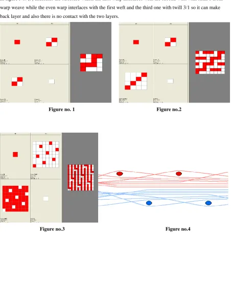
In Figure( 1) it is unclear to draw plain double face weave which definite numbers of threads and wefts , in the
first square the first warp interlaces with the first weft to make plain weave 1/1(warp and weft in the face side)
while the second vertical square refer to interlacing singular warps with even wefts in this case it is face weft
and we will raise all warps threads like the figure below ,in the second horizontal square it is refer to even warps
with face wefts which face wefts pass over all back warp threads ,in the last square the even warps overlapping
with even wefts using plain weave 1/1.
The figure No. (2) Indicates the way to draw double face structure in the face side we used twill 1/4 and the
back side used plain 1/1 and will raise all the face warps when we pass the back wefts so there are no contact
with the two layers.
The figure No. (3) Indicates the face side with satin 8 from warp and the back side satin 8 from weft and there is
no contact with the two layers. But in figure no. 4 indicates the cross section to the warps (4 warps) from the
structure.
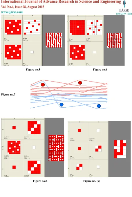
Figure No. (5) Shows satin 8 from warp in the face side and satin 8 from weft in the back side and we can see
that there is contact with the two layers with satin 8 from warp.
The figure no. (6) With the same structure to the face and back side and convert the contact structure when we
need to decrease numbers of contact marks in the structure for functional or aesthetical reason which we used
only 2 marks to contact offset 8 marks.While in figure no. (7) Indicates the cross section of part of the structure
In figure No. 8) indicates the double-face structure which form from two warp and three wefts and indicates that
the singular warp interlaces with the first warp with plain 1/1 weave while the even warps interlace with the
second weft while the third weft wadding in the two layers and will raise all face warps and reducing all back
warps when passing.
In figure No. (9) Indicates the structure which the first warp interlaces with the second weft with satin 8 from
warp weave while the even warp interlaces with the first weft and the third one with twill 3/1 so it can make
back layer and also there is no contact with the two layers.
Figure no. 1 Figure no.2
Figure no.5 Figure no.6
Figure no.7
Figure no.8 Figure no. (9)
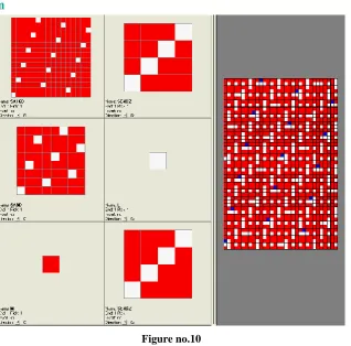
Figure no.10
In figure no. (11) third – double face structure, the first warp interlaces with the first weft in plain 1/1 weave so
it will form face layer and the second warp with the second weft will form the middle layer while the third warp
with the third weft will form the third layer(back layer) .
And in figure no. (12) Indicates the cross-section to this structure.
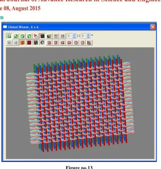
Figure No. (13) Indicates a simulation to the third-double face structure while figure no. (14) Indicates the same
structure from different corner.
Figure no.11 Figure no.12
Figure no.13
Figure No. (13) Indicates a simulation to the third-double face structure, while Figure no. (14) Indicates the
same structure from different corner.
2. Experimental work:
After a review of the last cases and how the program work we will use the program to make some composite
structures and using it to produce some samples which appear from it, some of aesthetical and functional
characteristics to the produced fabric.
And this is proposed as follows:
Warp: polyester 100/1 denier -72 warps/ cm.
Weft: 5 colors -16 pick /cm for one color.
Polyester yarn 300/ 1 denier.
Specifications of the Machine Used in Producing Samples understudy:
The research samples were produced using an electronic jacquard machine with the specifications
Type of the machine Rapier
Width of warp without selvedge 140 cm
Speed of the machine 300 picks per minute
Reed used (dents per cm) 9 dents per cm
Denting 8 ends per dent
In the following shapes it can indicate group of structures which it is suggested by program depending on
double face principle and do not put any contact marks to keep structures look and make a jut depending on
double face structure with wadding wefts and using satin 8 from the even warp to the fifth weft which shrink
when exposed to heat so it can help increasing (juts) the higher layer and making contacts depending on
exchanging with layers.
3. Result and Discussion:
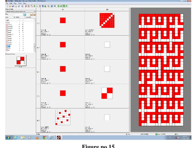
In figure no. (15) indicates appearance to the first weft with satin 8 from weft on the singular warp while the
third and fourth wefts are wadding and the second weft and the fifth is in the back side with the even warp in
plain 1/1, and the fifth with twill 7/1 and take care fixing the fifth weft structure in ,all structures to suitable
moving which can shrinking with a thermal processing.
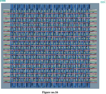
Figure no.16
Figure No. (16) Shows the second weft with satin 8 from weft and the third and fourth are wadding, and the first
weft and fifth are in the back side with the second part of warp threads.
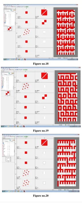
In figure no. (18) Shows the appearance of the third weft and the first wefts and the third one is wadding while
the fourth and the fifth weft are in back side with the second warp threads.
In figure no.(19)shows the appearance of the fourth weft and the first weft threads and the second one is
wadding while the third and fifth weft are in the back side with the second part of warp threads.
Figure no.18
Figure no.19
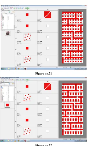
Figure no.21
Figure no.22
In figure no. (20) The appearance of the two wefts in the face side and the third and fourth are wadding layer
while the fifth weft is in the back side with the second warp threads.
In figure no. (21) Indicates the appearance of the first and third weft in the face side and the second and fourth
weft are in the wadding layer while the fifth weft is in the back side with the second part of the warp threads.
In figure no. (22) indicates the appearance of the first and fourth weft are in the face side , the second and the
Figure No. (23)
In figure no. (23) Indicates the appearance of the second and the fourth weft in the face side and the first and the
third weft are in the wadding layer while the fifth weft is back with the second part of the warp threads.
To reduce the possibility of inaction between the warp threads in spite of different crimp between the singular
and even wefts we can make exchange to the face and the back threads in some structures but we should know
that may be impress on the appearance of the produced fabric.
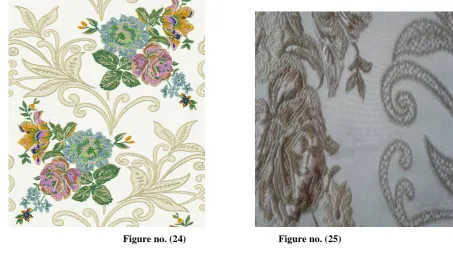
Forms No(24). describes designs which produced, while in the pictures no. (25) that were produced which
reflected through aesthetic and textiles that obtained as a result of the diversity of textile structures used as
chromaticity areas. As evidenced by the samples pictures implemented the occurrence and the textures obtained
as a result of the use of back weft after thermal processing of samples and the contraction of the back weft and
emergence pattern areas compared to ground areas.
IV. CONCLUSIONS
1- when using the composite method to draw textile weaves than innovative designer capabilities through easy
draw and group it and change them and provide substitutes.
2-This method enables the textile designer to understand how to build textile weaves in case of multiplicity of
wefts, and reach the largest possible number of textile weaves both appear individually or in multiple ways to
mix them.
3-Also, familiarity with the nature of textile weaves used helps the designer to choose the appropriate color
spaces to arise which contribute to improving the aesthetic values as well as the properties of produced fabrics.
REFERENCES
[1]. Computer –Assisted Structural Design of Industrial Woven Fabrics
Part 1: Need, Scope, Background, System Architecture- P.H Dastour , S.P Hersh ,S.K Batraand
W.J.Rasdorf,College Of Textiles, North Carolina State University ,Raleigh,NC27695,USA.
[2]. An Expert System For The Design Of Paper Handling System Computer ,Mittal ,S.Dym, C.L and
Morjaria,M.Pride.
[3]. manual of Ned Graphics program
[4]. 4- manual of Cad Vantage Win Developed by Teckmen Systems
[5]. Fabrics structure and design N.Gokarneshan senior lecturer deptt. textile technology kumaraguru college of
technology Coimbatore 641006
[6]. Design of Woven fabrics—Shababane and Blinov, Mir Publishers, Moscow