Department of Electronic and Electrical Engineering University College London
University of London
T
h e
E
v o l u t i o n
o f
C
o n t r o l
A
r c h it e c t u r e s
T
o w a r d s
N
e x t
G
e n e r a t i o n
N
e t w o r k s
By
Christos Solomonides BEng(Hons), MRes(Distinction)
7 September 2001
ProQuest Number: U643054
All rights reserved
INFORMATION TO ALL USERS
The quality of this reproduction is dependent upon the quality of the copy submitted.
In the unlikely event that the author did not send a complete manuscript and there are missing pages, these will be noted. Also, if material had to be removed,
a note will indicate the deletion.
uest.
ProQuest U643054
Published by ProQuest LLC(2016). Copyright of the Dissertation is held by the Author.
All rights reserved.
This work is protected against unauthorized copying under Title 17, United States Code. Microform Edition © ProQuest LLC.
ProQuest LLC
789 East Eisenhower Parkway P.O. Box 1346
A
b s t r a c t
This thesis describes the evolution o f control architectures and network intelligence towards next generation telecommunications networks. Network intelligence is a term given to the group of architectures that provide enhanced control services. Network intelligence is provided through the control plane, which is responsible for the establishment, operation and termination of calls and connections.
The work focuses on examining the way in which network intelligence has been provided in the traditional telecommunications environment and in a converging environment. In the case of the traditional telecommunications environment, the thesis examines the Intelligent Network (IN) architecture as a case scenario. In the case of the converging telecommunications environment, the work focuses on examining the relation and impact of emerging architectures and protocols and the ways in which these can inter-work with the IN. The discussion is presented using a taxonomy reference model of network intelligence architectures and their relation to the IN. For example, a protocol based on existing IN capabilities is presented that allows end users to engage in electronic commerce without the need for credit cards.
The control plane architecture in the Public Switched Telephony Network (PSTN) is heavily based on state machines. The role of state models and the reliance of IP-based protocols on state models are also examined. For this, IP-based architectures are examined and the extent of state utilisation is presented. This enables a classification of IP-based architectures and protocols to be drawn with regard to state utilisation.
A
c k n o w l e d g e m e n t s
I would like to express my deepest appreciation and gratitude to my supervisor Dr. M. D, Searle for his constant support, encouragement and guidance throughout this project. Without his help this work would never have been completed.
I would like to express my most sincere gratitude to my family for their unfailing support. To my Father who has provided me with the enthusiasm to complete this work. To my Mother for her continuous encouragement that has enabled me to successfully complete this work. Without the moral and financial help of my parents I would never have undertaken this work and for this I dedicate the work to them. I would like to extend this to my brother for always being there and supporting me at difficult times.
My deepest heartfelt appreciation is offered to my wife Vania Bastajian for her patience and support.
I would sincerely like to thank Adonis Michael ides for his support and genuine friendship.
I would also like to sincerely thank the following people: Aram Bastajian for taking the time to proof read the text; Christos Drakos for his support; Aristos Michaelides for his sincere encouragement; Jason Spencer and Ognjen Pmjat for their friendship and support; Chryssanthos Kouriefs and Melina Georgiou for providing me with hours o f entertainment and helping me cope with the work.
My sincere thanks go to all the staff at INSIG Ltd for allowing me to engage in activities that have provided me with the practical experience that compliments the theoretical aspects of this work.
T
a b l e
o f
C
o n t e n t s
ABSTRACT...2
ACKNOWLEDGMENTS... 4
TABLE OF CONTENTS...5
LIST OF FIGURES... 11
LIST OF TABLES... 15
CHAPTER 1: INTRODUCTION...16
1.1 Mo t i v a t i o n...16
1.2 Aim sa n d Ob j e c t i v e s...17
1.2 Th e Pr o b l e m Fie l da n dt h e Ap p r o a c h... 17
1.3 Su m m a r yo f Ma in Co n t r i b u t i o n s... 18
1.4 Th e s is Ou t l i n e... 19
CHAPTER 2: TRADITIONAL APPROACH TO NETWORK INTELLIGENCE... 21
2 .1 In t r o d u c t i o n... 21
2.1.1 Introduction to Telecommunications Networks...22
2.1.2 Distribution o f Service L ogic...24
2.1.3 Historical Switching and Signalling...27
2.1.4 The Strowger Switch...28
2 .2 Sw it c h in ga n dt h e Ro l eo f Si g n a l l i n g...2 9 2.2.1 Access Network...30
2.2.2 Core Network...30
2.2.3 Channel-Associated Signalling...31
2.2.4 Common-Channel Signalling...31
2 .3 Co m m o n-Ch a n n e l Si g n a l l i n g Sy s t e m No. 7 ... 3 2 2 .4 Th e In t e l l i g e n t Ne t w o r k... 3 4 2.4.1 The Intelligent Network Conceptual Model...36
2.4.2 The IN Service Processing Model and the Basic Call Process...38
2.4.3 IN Capability Sets...39
2.4.3.1 IN Capability Set 1 (C S-1)... 40
2.4.5.2 IN Capability Set 2 (C S-2)... 42
2.4.3.3 Inter-working Functions in Future Capability S ets... 44
2.4.4 The Basic Call Model...46
2.4.4.1 The Basic Call State Model for CS-1... 47
2.4.4.2 The Basic Call State Model for C S-2... 48
2.4.5 The IN Switching State Model (IN-SSM)...50
2.4.7 IN Summary...53
2 .5 Th e IN , t h e T I N A Re f e r e n c e Ar c h it e c t u r ea n d Ne w Te c h n o l o g i e s...5 4 2 .6 St a t e Ma c h in e si n Te l e c o m m u n i c a t i o n s Ne t w o r k s... 5 7 2 .7 Ch a p t e r Su m m a r y... 6 0 CHAPTER 3: TOWARDS A NEW ROLE FORNETWORK INTELLIGENCE IN THE CONVERGING ENVIRONMENT...61
3 .1 In t r o d u c t i o n... 61
3 .2 In t e r n e t-Pr o t o c o l Ba s e d Ne t w o r k s... 6 2 3 .3 A Ta x o n o m y Re f e r e n c e Mo d e lf o rt h e I N Ar c h i t e c t u r e...6 5 3.3.1 Support o f PSTN: The IN as the Control Architecture...66
3.3.1.1 Broadband M ultim edia S erv ices... 67
3.3.1.2 Internet (IP)-Based S e r v ic e s... 67
3.3.1.3 Other M ultim edia S e r v ic es...68
3.3.2 Using IP-Based Architectures to Support the IN M odel...68
3.3.2.1 PINT and IETF Protocols and Architectures Requiring IN Inter-operability... 68
3.3.2.1.1 The Session Initiation P ro to co l...69
3.3.2.1.2 The Session D escription P ro to co l...69
3.3.2.1.3 The PINT Architecture...69
3 .3.2.1.4 PINT and IN C S - 4 ...70
3.3.2.2 Computer T elephony Integration Call M o d e l... 73
3.3.2.3 Java Telephony A P I... 74
3 .3.2.4 Open Inter-working Standards...78
3.3.2.4.1 The Parlay Group... 79
3 .3.2.4.2 JAIN: Integrated N etwork APIs for the Java Platform ...80
3.3.2.4.3 Integrating Control Elem ents from JCC, JCAT and J T A P I...81
3.3.2.4.4 JAIN and Parlay...82
3.3.2.5 Internet Call Waiting: Replacem ent Initiative to IN Call W a itin g ... 83
3.3.3 Supporting IP-Based Services using the IN M odel...85
3.3.3.1 Customer Service System s... 86
3.3.3.2 Authentication, Certification, B illing and E-Com m erce S ervices...86
3 .3 .3 .3 D N S for M obility... 86
3.3.3.4 M EGACO and H .2 4 8 ...87
3.3.3.5 ETSI Project T IP H O N ... 88
3.3.4 Using the IN Architecture fo r Layer 2 Operations and to Support the Convergence Process. 92 3 .4 Th e Ro l eo ft h e T I N A Se r v ic e Ar c h it e c t u r eina Co n v e r g i n g En v i r o n m e n t...93
3 .5 St a t e Ma c h i n e si n Co n v e r g in g Ne t w o r k sa n d t h e Ro l eo f I N ...9 6 3 .6 Ch a p t e r Su m m a r ya n d Re s e a r c h Co n t r i b u t i o n s... 9 7 CHAPTER 4: UTILISING EXISTING IN INFRASTRUCTURE FOR IP-INITIATED BILLING & ELECTRONIC PAYMENT SYSTEM S...99
4.2.1 Limitations with Traditional Payment Systems...101
4 .3 De s ir a b l e Ch a r a c t e r is t i c so f El e c t r o n ic Pa y m e n t Sy s t e m s... 103
4.3.1 Security and Data Transmission...103
4.3.2 Authentication...103
4.3.3 Transaction Cost and Use o f Additional Hardware...105
4.3.4 Traceability o f Payments...106
4.3.5 Acceptability and Transferability...107
4.3.6 Implementation Issues...107
4 .4 Th e IE P S I N -b a s e d Bil l in g Sy s t e m... 108
4.4.1 Overview o f the IEPS M odel...108
4.4.2 Elements o f the IEPS...109
4 .5 Th e IE P S Pr o t o c o l... 110
4.5.1 Phase 1: User Connects to IS P...I l l 4.5.2 Phase 2: User Exchanges IP Packets...112
4.5.3 Phase 3: Charging using the IN Gateway...115
4 .6 Se c u r i t yw it h int h e IE P S Sy s t e m... 115
4.6.1 Elements o f a Public Key Infrastructure...115
4.6.2 PKI and the IEPS System...116
4 .7 Ev a l u a t i o no ft h e IE P S Pr o t o c o la sa n E P S ... 116
4.7.1 Software-only versus Tamperproof Hardware...117
4.7.2 System Security and Data Transmission...117
4.7.3 Transaction Cost...117
4.7.4 Traceability o f Payments...117
4.7.5 Acceptability and Transferability...118
4.7.6 Comparison with Currently Available Systems...118
4 .8 I N C S -1 In f o r m a t i o n Fl o w sf o r IE P S Re g i s t r a t i o n... 118
4.8.1 The SCF-SSF Interface...119
4.8.2 The SCF-SRF Interface...120
4.8.3 The SCF-SDFInterface...120
4.8.4 Resuming Processing at the SSF...121
4 .9 Th e Ga t e w a yb e t w e e n I N a n d I P ...121
4.9.1 The Gateway as an SR F...122
4.9.2 The Gateway as an SSF....122
4 .1 0 Ch a p t e r Su m m a r ya n d Re s e a r c h Co n t r i b u t i o n s... 123
CHAPTER 5: IMPLEMENTATION & SIMULATION OF THE IEPS SYSTEM ... 125
5.1 In t r o d u c t i o n... 125
5 .2 Im p l e m e n t a t i o no ft h e IE P S Pr o t o c o l... 125
5.2.0 WRITE_ORDER_DETAILS....127
5.2.1 TRANSACTION_START_REQUEST (TSReq)...128
5.2 J PUBLICJΠYJΠSP O N SE (PKRes)...128
5.2.4 TRANSACTION_DETAILS_TO_USER (TDUser)...129
5.2.5 TRANSACTION_DETAILS_TO_1S (TD ls)...129
5.2.6 USER_TO_GATEWAY(UtoG)...130
5.2.71S_T0_GATEWA Y (IStoG)...130
5.2.8 A UTH0R1SE_TRANSACT10N_REQUEST (ATReq)...132
5.2.9 AUTH0R1SE_TRANSACT10N_REPLY (ATReply)...132
5.2.10 PROCEED_T0_B1LL (PTB)...133
5.2.11 B IL L...133
5.2.12 CHARGE...133
5.3 The IEPS Classes... 133
5.3.1 The dbManagement Class...134
5.3.2 The myPacket C lass...135
5.3.3 The mySocket Class...135
5.3.4 The TCPServer Class...136
5.3.5 The UServer Class...137
5.3.6 The GServer Class...138
5.3.7 The ISServer Class...139
5.3.8 The SCPServer C lass...140
5.4 Resultsofthe IEPS Simulation... 141
5.4.1 Output from the isServer...141
5.4.2 Output from the gServer...142
5.4.3 Output from the userServer...142
5.4.4 Output from the scpServer...143
5.4.5 Output from the IS Servlet Server...143
5.4.6 The Applet Output...144
5.5 Chapter Summaryand Research Contributions... 144
CHAPTER 6: USE OF STATE IN ARCHITECTURES & PROTOCOLS IN THE IP DOMAIN...146
6.1 Introduction...146
6.2 Controlling State-Dependent Behaviour... 146
6.2.1 Deciding on an Adoption Policy fo r State-Dependent Behaviour...147
6.2.2 Representation o f State...148
6.2.2.1 Interfaces... 148
6.2.2.2 Logical State... 148
6.2.2.3 History and Execution States... 149
6.2.3 Implementation o f Guarded Suspension...150
6.2.3.1 Waits and Busy-Waits...150
6.2.3.2 Interrupts... 151
6.2.4 Tracking State...152
6.2.5 Optimistic Policies...152
6 .3 Us eo f St a t ein Cl ie n t- Se r v e r Ar c h i t e c t u r e s...153
6.3.1 Remote Authentication and Dial-In User Service...154
6.3.2 Authentication, Authorisation and Accounting...156
6.3.3 Common Open Policy Service Protocol...159
6.3.4 Web Servers...160
6.3.5 The Session Initiation Protocol Revisited...161
6.3.6 Integrated Services Architecture...162
6.3.7 Use o f State in Client-Server Architectures: A Summary...162
6 .4 Us eo f St a t ein Dis t r i b u t e d Ob j e c t Te c h n o l o g ie s & Ar c h i t e c t u r e s... 16 4 6.4.1 Common Object Request Broker Architecture...165
6.4.2 Enterprise Java Beans...165
6 .5 A St a t e- Ba s e d Cl a s s i f i c a t i o no f I P -Ba s e d Pr o t o c o l s... 16 7 6 .6 Ch a p t e r Su m m a r ya n d Re s e a r c h Co n t r i b u t i o n s... 171
CHAPTER 7:INVESTIGATING STATE MODELS IN THE IP-DOMAIN THROUGH A WEB-BASED NETWORK MANAGEMENT SYSTEM... 172
7 .1 In t r o d u c t i o n... 172
7.1.1 Motivation and Approach...172
7.1.2 Introduction to the Simple Network Management Protocol...174
7 .2 Th e Ne t w o r k Ma n a g e m e n t Sy s t e m... 175
7.2.1 Communication across the Components...177
7.2.2 The DB Interface and the DB Agent...177
7.2.3 The SNMP Agent and the SNMP Interface...178
7.2.4 The NMS Components...179
7.2.5 The Web Server and the Applet...179
7 .3 Di s t r i b u t e d St a t e- Ba s e d Be h a v i o u ro ft h e N M S ... 1 8 0 7 .4 Ch a p t e r Su m m a r ya n d Re s e a r c h Co n t r i b u t i o n s... 182
CHAPTER 8: OPEN PROGRAMMABLE NETWORKS, APPLICATION SERVERS AND NETWORK INTELLIGENCE... 183
8.1 In t r o d u c t i o n... 183
8 .2 Op e n Ne t w o r k s...18 4 8.2.1 Traditional View on Service Implementation...184
8.2.2 Open Network Access through APIs...186
8.2.3 Hierarchical Third-Party Service Provisioning...187
8 .3 IN -B A SE D Ap p l ic a t io n Se r v e r... 1 89 8.3.1 WhylN-Based?...189
8.3.2 API Server Logical Interfaces...190
8.3.4 A P I Server State Model...193
8.3.5 Server State M odel...194
8.3.6 Client State Model...195
8.4 Us i n g SDL t o Si m u l a t et h eAPI Se r v e r... 196
8.4.1 UML Sequence Diagrams...196
8.4.1.1 Accessing the Parlay Framework... 197
8.4.1.2 The Alarm Call (WakeUp) Application Example... 198
8.4.2 Simulation Overview...199
8.4.2.1 Client-Side Specification of Parlay API... 199
8.4.2.2 Server-Side Specification of Parlay API... 204
8.4.3 Simulation...206
8.5 Su m m a r y a n d Co n c l u s i o n s... 206
CHAPTER 9: CONCLUSIONS AND FURTHER W O RK ...208
9.1 Di s c u s s i o n... 208
9.2 Su m m a r y o f Co n t r i b u t i o n s...211
9.3 Fu r t h e r Wo r k...212
CHAPTER 10: REFERENCES...214
APPENDIX A: LIST OF ACRONYMS & ABBREVIATIONS... 241
L
i s t
o f
F
i g u r e s
Figure 2.1 : The hierarchy of the PSTN network... 24
Figure 2.2: Switch-based service provisioning in the traditional POTS environment adopted from [M age96]...24
Figure 2.3: Service provisioning in an IN environment...25
Figure 2.4: IN implementation of freephone service... 26
Figure 2.5: A fully interconnected mesh topology... 29
Figure 2.6: Channel-associated and common-channel signalling...31
Figure 2.7: The SS7 protocol stack in relation to the OSI reference model...32
Figure 2.8: Signalling points within the SS7 netw ork...33
Figure 2.9: The four planes of the IN conceptual model...38
Figure 2.10: The Intelligent Network service processing model [Q.1201]...38
Figure 2.11: The BCP in the global functional plane... 39
Figure 2.12: Distributed functional plane for IN CS-1 [Q.1211]... 41
Figure 2.13: Distributed functional plane for IN CS-2 [Q.1221]... 43
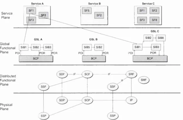
Figure 2.14: Example of a possible mapping of IN functional entities into IN physical entities supported by IN CS-2 [Veni98]... 44
Figure 2.15: IN and inter-working functional relationships... 45
Figure 2.16: The BCM, detection points and points in c a ll... 46
Figure 2.17: Separation of the BCSM into an 0 /T B C SM ... 47
Figure 2.18: The 0_BCSM for IN CS-1 [Q.1214]...48
Figure 2.19: The T BCSM for IN CS-1 [Q.1214]... 48
Figure 2.20: The 0_BCSM for IN CS-2 [Q.1224]...49
Figure 2.21: Representation used in a call configuration...51
Figure 2.22: Representation of a call association object...51
Figure 2.23: Finite state model for CPH of IN CS-2 [Kumm98]... 53
Figure 2.24: The TINA service architecture [TINA-SA]...55
Figure 2.25: The CAMEL architecture... 57
Figure 3.1: IN control plane taxonomy reference m odel...65
Figure 3.2: The Intelligent Network providing support to the P S T N ... 66
Figure 3.3: The Intelligent Network is supported by new IP technologies...68
Figure 3.4: PINT architecture... 70
Figure 3.5: Enhanced functional architecture for IN support o f IP networks [Q.1244]...71
Figure 3.6: Possible CTI network configuration... 73
Figure 3.7: Connection state model for CTI [ECTF97]...74
Figure 3.8: Objects within the JTAPI model [JTAPI]... 75
Figure 3.9: State model for Connection object...75
Figure 3.10: State model for Terminal Connection object...76
Figure 3.11: Architecture of the Parlay A P I... 79
Figure 3.12: Location of JAIN within a communications network [JA IN ]... 81
Figure 3.13: JAIN/Parlay Interactions... 83
Figure 3.14: ICW based on existing IN CS-1 FEs [RFC2995]... 84
Figure 3.15: Support o f IP with I N ...85
Figure 3.16: MEGACO NAS reference architecture... 88
Figure 3.17: H.248/MEGACO... 88
Figure 3.18: TIPHON release 1 architecture with reference points [ETSI TS 101-312]...89
Figure 3.19: TIPHON release 2 functional planes...89
Figure 3.20: Functional layers in the IP Telephony Application plane [ETSI TS 101-314]... 90
Figure 3.21: Mapping of IN functions onto TIPHON functional architecture...91
Figure 3.22: Call model integration framework...92
Figure 3.23: ICW based on existing IN CS-1 F E s... 92
Figure 3.24: SCPs responsible for the communication session... 94
Figure 3.25: The TINA service architecture, PINT, Parlay, and JAIN ...95
Figure 4.1: Parties involved in IEPS framework... 108
Figure 4.2: IEPS network elements... 109
Figure 4.3: Registration phase of IEPS...I l l Figure 4.4: The IP packets of the IEPS... 112
Figure 4.5: IN CS-1 IFs for the registration phase of the IEPS protocol... 119
Figure 4.6: The gateway as an S R F ...122
Figure 4.7: The gateway as an SSF... 122
Figure 5.1: Deployment of IEPS... 126
Figure 5.2: Data as a linked list... 130
Figure 5.3: Monitoring for matching pairs using shared local d ata... 131
Figure 5.4: Class diagram for dbManagement... 134
Figure 5.5: Class diagram for myPacket...135
Figure 5.6: Class diagram for mySocket...135
Figure 5.7: Class Diagram for TCPServer... 136
Figure 5.8: Class diagram for UServer...137
Figure 5.9: State transition diagram for UServer class... 137
Figure 5.10: Class diagram for GServer...138
Figure 5.11: State transition diagram for GServer class... 138
Figure 5.12: Class diagram for ISServer...139
Figure 5,13: State transition diagram for ISServer class... 139
Figure 5.14: Class diagram for SCPServer... 140
Figure 5.15: State transition diagram for SCPServer class...140
Figure 5.16: Simulation output from the IS Server...141
Figure 5.17: Simulation output from the Gateway Server...142
Figure 5.18: Simulation output from the User Server (continues on next page)...142
Figure 5.19: Simulation output from the SCP Server... 143
Figure 5.20: Output from the Servlet simulator...143
Figure 5.21 : Simulation output from the applet...144
Figure 6.1: Guarded suspension... 150
Figure 6.2: State transition diagram for RADIUS client... 155
Figure 6.3: State transition diagram for RADIUS server... 155
Figure 6.4: Basic authorisation entities, service agreements, and access methods...157
Figure 6.5: Distributed services and agreements...157
Figure 6.6: The primary policy control architecture components... 159
Figure 6.7: SIP server state transition diagram... 162
Figure 6.8: Communication between resource managers across administrative domains 163 Figure 6.9: Stateful session bean state diagram based on EJB...166
Figure 6.10: Classification of state-dependent architectures...167
Figure 6.11: Distributed control with RMs residing across administrative boundaries... 169
Figure 6.12: Application entity structure adopted from [Q.1208]... 170
Figure 6.13: The management layer interface... 170
Figure 7.1: Example of the components of a Network Management System... 174
Figure 7.2: Interfaces o f the NMS... 176
Figure 7.3: Communication between the applet, web server and N M S...177
Figure 7.4: The DB Agent class... 178
Figure 7.5: The SNMP Agent class... 178
Figure 7.6: The N M S ... 179
Figure 7.7: Extensions to the NMS architecture...181
Figure 8.1: Traditional approach to service provisioning... 184
Figure 8.2: Hierarchy of third-party service providers... 188
Figure 8.3: Logical interfaces o f the API Server...190
Figure 8.4: The API Server architecture... 191
Figure 8.5: Details of the API Server architecture...192
Figure 8.6: The API Server state m odel...193
Figure 8.7: The Server state model (S_SSM )... 194
Figure 8.8: The Client state model (C SSM)... 196
Figure 8.9: UML sequence diagram showing an application accessing
a Parlay Server adopted from [ParlaySeq99]... 197
Figure 8.10: UML sequence diagram for an Alarm Call Service adopted from [ParlaySeq99] 198 Figure 8.11: Specification of the Wakeupapplication system... 201
Figure 8.12: Part o f the IparlayAppLogic state diagram... 201
Figure 8.13: Part o f the Parlay Access block showing process IparlayAppAuthentication receiving signal authenticateClient from the environment via channel C3...202
Figure 8.14: Part of process IparlayAppAuthentication... 203
Figure 8.15: Process AccTimeOutl generating output signal accTim eoutl... 204
Figure 8.16: Sequence diagram of alarm call service, adopted from [ParlaySeq99]... 205
Figure 8.17: Part of block Parlay Server showing the implementation of process IparlayAuthentication interfacing to the system via R2 and R 3 ...206
L
i s t
o f
T
a b l e s
Table 3.1: Description of states for a Connection object...76
Table 3.2: Description of states for a Terminal Connection object... 76
Table 3.3: Standards for inter-working among IP Telephony and the PST N ...87
Table 4.1 : Packet structure for message 8... 113
Table 4.2: Record structure for IS agent... 113
Table 4.3: Packet structure for message 9 ... 113
Table 4.4: Packet structure for message 10...114
Table 4.5: Packet structure for message 11...114
Table 5.0: WRITE_ORDER_DETAILS packet structure... 127
Table 5.1: TRANSACTION_START_REQUEST packet structure...128
Table 5.2: PUBLIC_KEY_REQUEST packet structure... 128
Table 5.3: PUBLIC_KEY_RESPONSE packet structure... 128
Table 5.4: TRANSACTION_DETAILS_TO_USER packet structure...129
Table 5.5: TRANSACTION_DETAILS_TO_IS packet structure... 129
Table 5.6: USER TO GATEWAY packet structure... 130
Table 5.7: IS TO GATEWAY packet structure...130
Table 5.8: AUTHORISE_TRANSACTION_REQUEST packet structure... 132
Table 5.9: AUTHORISE_TRANSACTION REPLY packet structure...132
Table 5.10: PROCEED TO BILL packet structure... 133
Table 5.11: BILL packet structure...133
Table 5.12: CHARGE packet structure... 133
Table 6.1: Pessimistic and optimistic policies for state-dependent actions... 147
Table 6.2: Session and entity beans...166
Table 8.1 : Messages used by an application accessing a Parlay Server...198
Table 8.2: Messages used by an alarm call service...199
C
h a p t e r
1
I
n t r o d u c t i o n
C
hanges in telecommunications technology and the telecommunications environment provide sufficient ground for the proliferation of open service provisioning by third- party service providers. Such advances give rise to a number of issues relating to the control plane of telecommunications networks.1.1 M
o t iv a t i o nHistorically, telecommunications services were designed, developed and implemented with the traditional telecommunications network as the target environment. This is an environment with strictly standardised functional entities that are owned and maintained by the incumbent operator.
The telecommunications environment is changing: market dynamics, regulatory initiatives and technological advances are necessitating changes [Melo97] [ECOO] [PI 110] [Haya98] [Ishi98]. Such technological and market-related [Walk97] changes have an impact on the way in which control is provided. The control plane can be thought of as a collection o f hierarchically distributed functional entities whose aim is to establish, monitor and terminate the calls and connections. In the traditional environment, control and network intelligence is provided primarily by the Intelligent Network architecture. In the new telecommunications environment it is crucial for traditional telecommunications networks and services to inter-work with IP-based networks and services [Stro99]. The inter-operability and, therefore, the convergence process is driven by the demand of end users for seamless service access, regardless o f the transport network. Such a level of inter-operability requires a re-think in the way network intelligence is provided.
IP-based networks have shown explosive growth [AsatO 1 ] [ITU97] [ITUOO][ECOO]. Unlike in the telecommunications domain, the drive for new protocols, services, and capabilities has come from open groups, rather than from standardisation bodies. The IP approach does not require the presence o f an explicit control plane architecture that standardises external and internal state models; rather, the client-server architectures of the IP world are sufficient. This is supported by the way standardisation bodies such as the Internet Engineering Task Force (IETF) operate.
1.2 A
i m s a n dO
b j e c t iv e sThe thesis examines and identifies the control plane mechanisms that enable network intelligence in both telecommunication and data networks. In telecommunication networks, specifically the public switched telephony network (PSTN), a major architecture contributing towards control and intelligence is that of the Intelligent Network (IN). The thesis examines the IN architecture as a case scenario in order to pinpoint the mechanisms through which it enables services and therefore intelligence to be provided in a complex and distributed network such as the PSTN.
The work also aims at examining how the traditional view o f network intelligence is affected in the converging environment of telecommunication and data networks. To achieve this, the thesis examines current and evolving IP-based architectures and suggests ways in which inter operability with network intelligent architectures in the PSTN can be achieved. By doing this, the author presents a taxonomy that classifies numerous packet-switched protocols and their relation to the IN architecture.
The thesis also puts forward a classification of existing IP-based protocols according to their utilisation of state and state-dependent actions. The work shows the way in which state can be implemented and discusses the need for state-utilisation. More importantly, the author identifies some of the complexities that necessitate state-utilisation.
Finally, the thesis looks at the issues relating to the control plane within the framework of open programmable networks and initiatives for service provisioning by third-parties. The aim is to present an architecture for third-party service providers that draws from IN principles for providing control and intelligence.
1.2 T
h eP
r o b l e mF
ie l d a n d t h eA
p p r o a c hThe problem field that this research work focuses on is that of the control plane in next generation telecommunications networks. The control plane is of crucial importance in the converging environment of telecommunication and data networks. Unless there is a clear understanding of the way in which network intelligence can be offered - through the control plane - the inter-working of telecommunications services will be problematic. The problem statement can be summarised as: "What is the role o f network intelligence and the control plane in next generation telecommunications networks?”
The approach the author has adopted is one that represents a mixture o f practical and theoretical work. The theoretical work focuses on the role of the control plane in traditional and evolving telecommunications networks and services. The practical work involves the implementation and simulation of three systems, the aims of which were to: examine the role of existing intelligent network infrastructure; analyse the role o f the control plane in a distributed system in an IP- based environment; and to propose an application server architecture that is based on concepts from the IN world, but also draws from the flexibility and openness o f the IP domain.
1.3 S
u m m a r y o fM
a i nC
o n t r i b u t i o n sThe thesis presents both traditional and emerging network intelligence architectures within the converging telecommunications environment. By doing this it provides a unique view of the
current state of convergence. This is a useful and important contribution. The classification
presented in chapter 3, provides the reader with a chronological snapshot o f the convergence between telecommunication and computer science practices, principles and approaches. Such a classification has not been published before, and it is the author’s view that the taxonomy is useful for the categorisation of new computer science and telecommunication-based
architectures and their relation to the Intelligent Network. At the same time, such a
classification is important as it enables a reader with little background in either o f the two fields (telecommunications or computer science), to quickly understand the relation of existing network intelligent architectures to the Intelligent Network.
The author also presents an application for e-commerce, based on the Intelligent Network architecture, with support for micro-transactions without the need of credit cards. The application was designed, implemented and simulated by the author. Furthermore, a patent
application was also filed [lEPSPat]. The application is entirely based on existing IN
capabilities, and requires no change in the telecommunications environment.
Another important contribution is the classification of IP-based architectures with respect to
their utilisation of state. The author scrutinises numerous IP-based protocols and frameworks
and shows that although some systems may be characterised as “stateless”, the complexity of their operating environment may impose the introduction of “state” and/or “state dependent actions and events”. Specifically, the author argues that in certain systems, the utilisation of state is imposed by the concurrency complexities o f the system and not the complexities of the system p erse.
The thesis also puts forward an architectural framework for the communication of
third-party service providers within an open network service provisioning environment. The
framework, proposed by the author, conforms to the Parlay API’s framework interfaces for allowing the interconnection of third-party service providers. The architectural framework is based on the principles of the IN control architecture and also on the flexibility exhibited by IP- based architectures. Incorporated within the framework are state machines that aim and achieve to simplify the billing and management of services in an open network environment. The framework is necessary as new third-party service providers are
The work presented in this thesis is supported by the following publications o f the author: 1. C. Solomonides and M. Searle, “/A and the INternet”, University College London,
London Telecommunications Research Symposium, London, July, 1998.
2. C. Solomonides and M. Searle, ''''Relevance o f Existing Intelligent Network Infrastructure to the Internet, University College London, Lecture Notes in Computer Science, Springer-Verlag, 5th International Conference on Intelligence and Services in Networks, IS&N'99, Barcelona, Spain, April 1999.
3. C. Solomonides and M. Searle, "An Intelligent Network E-Commerce ProtocoN, University College London, 38th European Telecommunications Congress, Utrecht, The Netherlands, August 1999.
4. C. Solomonides and M. Searle, "Evolution Towards the TINA Service Architecture Through PINT and Parlay”, 6th International Conference on Intelligence in Networks, 17-20 January 2000, Palais Des Congres D'Archachon, Bordeaux, France, 2000.
5. C. Solomonides and M. Searle, "Intelligent Network Application Programming Interface Server Architecture”, University College London, IEEE IN 2000 Workshop, Cape Town, South Africa, May 2000.
6. C. Solomonides and M. Searle, "Network Intelligence, APIs and Service Creation”, University College London, 39th European Telecommunications Congress, Limerick, Ireland, August 2000.
7. C. Solomonides and M. Searle, "Application Server Architecture fo r Open Networks”, University College London, London Telecommunications Symposium, London, September 2000.
1.4 T
h e s isO
u t l in eChapter 2 provides a short background to telecommunications concepts that are relevant to this thesis and discusses the traditional approach to network intelligence. The Intelligent Network is
presented and the mechanisms through which it provides the control plane for telecommunications networks are analysed.
Chapter 3 aims at examining current research activities in network intelligence and presents these in relation to the Intelligent Network architecture. It also examines the new role of the Intelligent Network: that is, the IN as a control architecture that provides ways to initiate services on the PSTN. Within this context, the chapter discusses ways of using the IN as it currently is but also identifies the additional functionality that is needed within a converging environment.
One of the areas in which the existing IN control architecture can be used unchanged is for providing authentication, certification and electronic commerce capabilities. This is examined in chapter 4, where a specific application area uses legacy IN to provide a desirable, secure and trusted platform for IP-based payments. The strength o f the protocol that is described lies in its ability to handle micro-transactions on behalf of the end users, without the need for credit cards. The implementation and simulation of the protocol is presented in chapter 5.
Chapter 6 examines the notion of “state” in IP-based protocols and architectures. The chapter presents the ways in which state can be maintained and implemented. Following this the chapter provides a classification of various IP-based architectures with respect to their reliance on state- dependent actions. The work presented in chapter 6 is applied in chapter 7 by presenting a network management system which aims at examining the control aspects in a distributed system. The network management system presented in chapter 7 draws from traditional telecommunication principles, but also from techniques traditionally found in the data networks environment.
Chapter 8 presents an application-server architecture based on principles from the IN environment, but also from computer-science practices. The application server that is presented in aimed towards third-party service providers. The chapter examines the need for such an architecture within the overall framework o f open network service provisioning.
Finally, chapter 9 gives the conclusions regarding the research work presented and provides suggestions for further work that may be undertaken as a result o f the author’s work.
C
h a p t e r
2
T r a d i t i o n a l A p p r o a c h t o
N e t w o r k I n t e l l i g e n c e
T
he aim of this chapter is to develop an understanding of the traditional role of network intelligence in telecommunications. This is done by outlining some key concepts such as switching, the role of signalling and their relation to control architectures such as the Intelligent Network. In doing this, the chapter presents a useful background to the new research conducted.2.1 I
n t r o d u c t i o nIn chapter 1 it was mentioned that one of the aims of the work is to examine the role of the control plane in traditional telecommunication networks. Chapter 2 supports this aim by examining the way in which control has been achieved in traditional telecommunications networks. Hence, a large section of this chapter deals with the control mechanisms and architectures that form part o f today’s telecommunications networks.
Network Intelligence is a term given to the group of architectures that provide enhanced control services. A number o f these will be examined in this thesis. One important example of network intelligence is called the Intelligent Network (IN) [Q.1200-Q.1205], discussed in this chapter. The IN is implemented as an overlay to the voice network and facilitates advanced call control services through its capability sets (CSs).
Telecommunications networks have been developed to support voice services. The basic services of such networks are discussed in section 2.1.1, while section 2.1.2 discusses the way service logic is distributed in an IN and non-IN environment.
Section 2.1.3 gives a brief history of the development of the telecommunications network. The motivation for providing a historical walkthrough is to understand that the evolution of a telecommunications network has been driven by the need to provide voice services with an extremely high quality of service. This basic requirement has also driven the characteristics of
the traditional telecommunications network. The fundamental characteristics of a telecommunications network are at odds with the features of an Internet Protocol network.
A telecommunications network typically comprises a number of planes. From the point of view of this thesis, the main ones are the transport and control plane. The transport plane provides the bearer connections on which voice channels are transported and the control plane supports the bearer channels through the signalling services. Section 2.2 examines the control plane and, in particular, the switching and signalling aspects of a telecommunications network. The key signalling protocol is Signalling System No. 7, which is discussed in section 2.3.
The IN control architecture is presented in detail in section 2.4, where the focus is to identify the major characteristics of any network intelligent architecture. An essential element of the IN is its reliance on state models, which will become apparent through the discussions in this chapter.
While architectures such as the IN focused on standardising the technical issues, others such as the Telecommunications Information Network Architecture (TINA) [TINA-GA] had a wider scope, attempting to address and standardise less technical issues such as the business and managerial structures [TINA-BM]. The TINA model is presented in section 2.5. However, the focus is on the relation of IN to TINA, rather than the TINA architecture per se. Finally, section 2.6 focuses on the use of state models in telecommunications networks.
2.1.1 Introduction to Telecom m unications N etw orks
The aim of any communications network is to provide channels for the exchange of information.* In the traditional telecommunications world, the aim of the communications network has been to provide for the transfer o f speech. This has driven the structure and characteristics of the network.
Telecommunications networks have evolved significantly since their original conception even though, to a certain extent, the basic service offering has remained unchanged throughout this time. This is because the design requirements of the telephone network were set by the characteristics of human voice, which have not changed.
The telecommunications network is referred to as the “Public Switched Telephony Network” (PSTN). This has evolved from the traditional “plain old telephony service” (POTS) and adds
In traditional telecommunications involving voice, these “channels” can be thought of as physical
connections between the two subscribers.
new services such as freephone, credit card calling, etc. The rest of this section presents the basic concepts of the PSTN.
A network involves the interconnection of resources. The network topology dictates the number of links that are required, the cost of the deployment, and possibly, the robustness of the network. As the network becomes distributed across geographical regions, there is a need for this interconnection if two or more networks are to communicate.
A subscriber in the PSTN can place a call from any geographical location to another subscriber who might be located thousands of miles away. This can be achieved using a hierarchical architecture of interconnected network components (see figure 2.1) between any two parties involved in a conversation. Having achieved the interconnection o f these geographically distributed networks, there is a requirement to notify network components (residing in the core of the network) so that one subscriber can initiate a call to another. This is achieved using switching and signalling. The process of switching and signalling results in resources (channels) being allocated between the calling (originating) and the called (terminating) parties. This pre allocation of resources for the duration of a call* is a fundamental principle in telecommunications networks. The PSTN approach is in stark contrast to the approach of data networks such as the Internet, where no pre-allocation o f resources takes place. The details involved in switching and signalling are the focus of the work presented in section 2.2.
Making a connection and allocating the resources requires a call to proceed through the following phases:
1. Pre-selection", where a new call request is recognised and decisions on how to deal with the call are made.
2. Call completion: the originating and terminating parties are connected and the charging process is initiated.
3. Conversation
4. Release: the call is disconnected, releasing the allocated resources, the billing record is completed, and the network returns to the normal (idle) state.
When channel-associated signalling is used (section 2.2.3), the resources are allocated when the
subscriber’s handset goes off hook and the signal is received by the local exchange.
International E x c h a n g e
Tertiary E x c h a n g e
S e c o n d a r y E x c h a n g e
L o ca l E x c h a n g e L ocal L oop
F igure 2.1: The hierarchy o f the P ST N netw ork
2.1.2 Distribution o f Service Logic
This section discusses the way in which service logic is distributed in two environments. Figure
2.2 illustrates the implementation o f a service without an IN eontrol architecture; figure 2.3
illustrates the way a service is implemented with an IN architecture. The section discusses the
two approaches to service distribution and im plem entation and puts forward the principles,
advantages and basic operation o f the IN.
Operations Administration and M anagem ent
( 0 AM) services 1..n
Switch A Service Logic
Service Data
Basic Call P rocessin g
Switch B Service Logic
Service Data
Basic Call Processing
Switch C Service Logic
Service Data
B asic Call Processin g
F igure 2.2: Sw itch-based service provisioning in the traditional P O TS environment adopted fro m [M age96]
Figure 2.2 depicts the com ponents o f the switches and the way service logic is distributed
without the IN control architecture. The switches enable the connection o f subscribers located at
the edges o f the network. Its components are the service logic, service data and basic call-
processing functionality.
The im plementation o f services without an IN control architecture has a number o f
disadvantages [Am br89][Eple90][Zolz92][Filk00]. The switches may be from different vendors
and, as a result, the service logic and data have to be customised for the vendor-specific
platform. To introduce new services, the service logic has to be im plemented on all the switches
and this task is costly due to the geographical distribution o f the switches. Subscribers can only
access services implemented by the local switch, unless the service logic is identical throughout
the network.
To achieve hom ogeneity at the switch-level means that a substantial proportion o f the operator’s
revenue and time is spent in updating the service logic at the switches. This is costly, time-
consum ing, and inefficient and, unfortunately, it was the only approach available until the
introduction o f the Intelligent Network architecture.
With the introduction o f the Intelligent Network, it becam e possible to im plem ent a service in a
more efficient manner, as shown in figure 2.3.
SOP Service Logic
Service Data
Switch A (S S P ) B asic Call Processing
Switch B (S S P ) B asic Call Processin g
Switch C (S S P ) B asic Call P ro cessin g
F igure 2.3: Service provisioning in an IN environm ent
The service logic now resides in a central node, called the Service Control Point (SCP). When
the individual switches require additional service functionality, that may not present in the
switch, it is provided by the SCP.
The separation o f basic call-processing from enhanced service logic enables the rapid
provisioning o f new services [Kun97]. This is because service logic is now centrally located,
and there is no need to individually update every single switch; a single update on the SCP is
sufficient.
To illustrate the operation o f an IN service, the freephone service* is presented in figure 2.4. The
following comm unication channels are used: com m unication between the Service Switching
Point (SSP) and the SCP/Service Data Point (SDP) is achieved via the signalling network, while
com m unication across the SSPs (switches) is over the bearer connection. The signalling links
are shown in figure 2.4 using dashed lines while the bearer connection is represented using the
solid line.
The process begins with the initiating party dialling “0800192192” . The local exchange (switch
A) recognises that this is a specific service access num ber as it begins with “0800” . It therefore
queries the SCP for call handling support. The SCP then queries the SDP, which contains a
database, in order to translate the “0800192192” logical num ber to the specific destination
number, for example “02073342123” . This translated num ber is passed back to switch A and
call handling resumes. Switch A now has sufficient information to be able to set up the call, i.e.
to establish the corresponding bearer connection to the appropriate final destination. When
either o f the two subscribers hangs up, the call is term inated in the usual m anner (i.e. by moving
to the Release phase).
0800-192192
02073342123
Service Logic
Service D ata
S C P S D P
D ata
0800-192192
<3 02073342123
- 0800-192192
Switch A (S S P )
6
Switch B (S S P )
Basic C all Processing Basic C all Processing
02073342123
F igure 2.4: IN implementation o f freephone service
The freephone service proved to be a desirable service with network operators and customers
alike. Indeed, British Telecom ’s reason for adopting the IN architecture was to enable freephone
* Freephone enables a calling party to dial a number without incurring charges. The call is charged to the terminating party.
and call-stream services [OBri89]. NTT in Japan, introduced an IN-like architecture in 1985, and the first service that was made available was freephone [Suzu93].
This introductory section provided a short description of the various elements that are involved in a modem telecommunications network. In summary, the main concepts that were introduced include the hierarchical and distributed nature of the network, the presence of a separate
signalling network to that of the bearer connections, the fundamental requirement of the
sharing of resources and their explicit allocation, service provisioning with and without the Intelligent Network, and some of the advantages o f the Intelligent Network. These concepts are further discussed in the following sections in this chapter.
Firstly, however, there is a short chronological walkthrough of the telecommunications developments up to the point of the introduction of the Intelligent Network to show that, at the initial conception of the telecommunications network, there was intelligence at the core, which was then removed.
2.1.3 H istorical Sw itching and Signalling
The aim of the POTS network was to provide the capability for voice communication among subscribers. At the time (late 1870s), the approach adopted was to interconnect subscribers through local offices. Within these offices, human operators were responsible for physically connecting the circuit between the caller and the destination subscriber using a switchboard.* This process is now known as circuit switching.
The presence of the human operator provided the “network” with a very significant capability - that of intelligence. Operators were in a position to know that the doctor was not at home, but at a friend’s house - and in this way could re-direct the call. In today’s environment, this is call forwarding. Furthermore, unwanted calls were filtered (call-screening) and messages could be left with the operator (voice-mail). When either of the two parties ended the conversation, the operator would terminate the connection. This would release the bearer channels and resources were no longer explicitly allocated to the two parties. It can be deduced that the explicit allocation of resources has had its roots in the original conception o f the network.
While the services described above were provided by the human operator, other services, for example, call queuing and call waiting were more difficult (if not impossible) to achieve, because of the limitation in the number of resources (bearer connections) and not due to lack of
* At the time, subscribers were important people in the community, such as doctors, policemen, etc.
intelligence. What is more, as the number of subscribers grew, operators struggled to keep up with the demand for switching [Russ98]. It then became evident that if the switching and connection process could be automated, it would provide lower running costs and therefore increased profits. Increasing the speed of the connection process also meant subscribers would spend more time talking rather than waiting to be connected.
The automation of the connection process required a component that could automatically switch and connect the originating and terminating parties. Unfortunately, the introduction of automated switches also removed the intelligence that was present.
2.1.4 T he Strow ger Switch
The first automated switch came from an unexpected source. Almon B. Strowger was an undertaker in Kansas City, USA in the late 1890s. The story says [AGCS] [Lesh98] [TeReOO] that there was a competing undertaker locally, whose wife was an operator at the local telephone exchange. Whenever a caller asked to be put through to Strowger, calls were deliberately put through to his competitor. This obviously frustrated Strowger greatly and he set about devising a system that would reduce the reliance on the human part of the equation. Strowger developed a system of automatic switching using an electromechanical switch based around electromagnets and pawls [AGCS]. With the help of his nephew, Walter S. Strowger, he produced a working model in 1888 under US Patent No. 447918 dated 6/I0/189I.
There was now however a need to re-introduce the network intelligence and the “advanced services” that were removed. O f course, the electromechanical switch developed by Strowger did not provide the necessary “environment” to be “software-controlled”. Software within switches was introduced with the development o f Stored Program Control (SPC).
By the early 1960s, advances in computer science* made it possible to develop software which could control devices. In May 1965, the No. 1 Electronic Switching System was put into commercial service in Succasunna, New Jersey. The switch utilised technology with a relatively slow central control, very expensive memory (Ferrite sheet and Twister), and slow peripherals [Memm90]. These factors adversely affected the development o f SPC-type switches - the competing crossbar systems were cheaper to manufacture.
In the early 1980s, digital switching began to appear and distributed control was more widely adopted - together with its overheads [Memm90]. Multiple control programs were accompanied
* Such as the introduction of the silicon transistor by Texas Instruments.
by multiple distributed databases and interactions among distributed programs and databases were a challenge. The software development practices in the 1980s did not exactly follow the software engineering principles of abstraction, coherence or decoupling [SommOl]. Instead, software was characterised by the “spaghetti approach” and endless use of the “goto” keyword.
The rest o f this chapter focuses on discussing the role of switching and signalling, followed by a detailed description of the IN control architecture.
2.2 S
w i t c h i n g a n d t h eR
o l e o fS
i g n a l l i n gIn an ideal world, communicating parties would be physically interconnected across a medium with no loss, delay or bandwidth limitations. In practice it is impossible to physically interconnect all the communicating parties in a mesh arrangement due to scalability, practicality and logistics.
Figure 2.5: A fully interconnected mesh topology
Equation (1) presents the total number o f links that are required if n nodes are to be connected in a fully-meshed arrangement, as shown in figure 2.5.
n - n
(1)
This is expensive if the number of nodes is large, as in the case of the PSTN where the number of nodes is in the order o f millions. For this reason, from its infancy the telecommunications network has adopted a hierarchical approach (see figure 2.1).
In order to enable the network to interconnect two subscribers in a hierarchical topology, switches (that are controlled through signalling) must be placed along the transmission path to direct the bearer connections from the caller to the person being called. The process of switching allows the physical interconnection of subscribers by directing a call path in a way that enables the caller to establish a bearer connection to the party being called [Russ98]. The size and position of the switches are carefully chosen using network planning and performance measurements, as their cost is very high.
The signalling netw ork is used to control the switches and its aim is to establish and maintain control connection paths through the link-by-link setting up o f a path [Russ98]. In doing so, valuable resources are allocated by the switches to establish the connection. To maintain the signalling network in an operational state and increase robustness, some o f the links at the various levels are interconnected (see figure 2.1).
The interconnection increases robustness in the case of link failure at the physical and transport planes. However, due to the importance of the signalling network it is also vital that the signalling protocol maintain mechanisms that provide resilience and robustness.
Signalling protocols such as Signalling System Number 7 (discussed in section 2.3) define ubiquitous state models to assist in ensuring the robustness and reliability o f the signalling network. The concept o f state models is a central issue to the work presented in this thesis (see particularly sections 2.6, 3.5, 6.6 and 7.3).
The signalling network is divided into two parts: the access network and the core network.
2.2.1 A ccess N etw ork
The access network is defined as the part of the network between the end terminal and the local exchange. Access network signalling in the POTS network utilises a very simple analogue signalling scheme called Dual Tone Multiple Frequency (DTMF) [ETSI TS 101 235]. DTMF signalling uses a set o f audible frequency tones in response to buttons being pushed on the telephone. The goal is for the telephone device to signal to the exchange across the user channel.
In the case of private businesses, the customer premises do not have a single telephone line but a large number of telephones in a private network. In such cases, a business often possesses a Private Branch Exchange (PBX). PBXs control the routing of calls within the business organisation and provide customised services between offices o f the same company. These services include the allocation o f personal number extensions across multiple office sites. The Digital Private Network Signalling System (DPNSS) is a scheme that interfaces the PBX with the local exchange. Access signalling has differing requirements from the trunk (core) network.
2.2.2 Core N etw ork
The core network is the part from the local exchange to internal signalling points, such as Signal Transfer Points (STPs). Core (inter-exchange) signalling between exchanges or switches establishes the resources for a call and optionally communicates supplementary service
requirem ents to an intelligent network platform , such as the Intelligent Network. The core
network uses core signalling schemes and protocols. SS7, the ubiquitous inter-exchange
signalling scheme, has evolved from a previous version nam ed Com m on Channel Signalling
System No. 6, developed by the ITU-TS (form erly CCITT) in the m id-1960s. SS7 employs
digital signalling.
Early signalling methods were limited because they used the same circuit for both signalling
and voice. The circuit would be busy from the time the caller started dialling until the caller
went “on-hook”. A solution to this was to separate the signalling and the bearer connections.
This way, the call setup and teardown procedures required with every call could be faster. Voice
and data circuits could be reserved for use when a connection was possible, instead o f
m aintaining the connection even when the destination was busy.
C h a n n e l - A s s o c i a t e d S ig n a l li n g C o m m o n - C h a n n e l s i g n a l l i n g
Bearer channel 1
Switch Switch
Signalling for bearer channel 1
Control System
Bearer channel 3
Signalling for
Control
System Switch Switch
Com m on Signalling Control
System
Control System
Channel bearer channel 3
F igure 2.6: C hannel-associated and com m on-channel signalling
2.2.3 C hannel-A ssociated Signalling
In channel-associated signalling (figure 2.6, left), the signalling m essages are sent across logical signalling channels that are dedicated to each speech channel. In other words, although
the signalling channel may be a separate physical channel from the voice (bearer) channel, a
dedicated channel is allocated to support the voice call. The disadvantage o f this technique is
that signalling resources are provided regardless o f w hether the voice channel needs it. There
are times in a call, such as the mid-call period, when less signalling information is required. At
such times it would be useful if the signalling channel could be used for another signalling
circuit.
2.2.4 C om m on -C han nel Signalling
In common-channel signalling (figure 2.6, right), signalling for a num ber o f voice channels is aggregated into a single shared (common) signalling channel. The introduction o f separate
signalling links means that a bearer (voice) connection is only utilised if a connection can be
established. As a result, the availability o f voice circuits is higher and the need for additional
circuits decreases. Com m on-channel signalling schemes include SS6 and SS7, as well as the
DPNSS and its successor QSig [ECMA-143],
2.3 C
o m m o n-C
h a n n e lS
ig n a l l in gS
y s t e mN
o. 7
Figure 2.7 depicts the Com mon-Channei Signalling System No. 7 (SS7) protocol stack in
relation to the OSI reference model [ISO-IS7498-1]. In contrast to IP netw orks, SS7 networks
do not adhere to the full seven-layer OSI reference model. This is because SS7 was developed
before the OSI reference model. SS7 adheres to a four-level model.
OSI la y e rs 8 5 7 le v e ls
Application lay er
P rese n tatio n layer
S e s sio n layer
T ran sp o rt layer
Network layer
D ata link layer
Physical layer
Mobile Application Part
Intelligent Network Application P art
T ran sactio n C apabilities Application P a rt (TCAP)
Signalling C o n n ectio n C ontrol P a rt (S C C P)
M e s sa g e T ran sfe r P a rt (MTP) Levels 1-3
Figure 2.7: The SS7 protocol stack in relation to the O SI reference model
The Message T ransfer Part Levels 1-3 [Q.701] define the physical transport, the data link layer and the netw ork layer. As in the OSI model, each layer is responsible for delivering a
service to the layer above it. In the case o f call-connection, MTP-3 provides an end-to-end
packet-based transfer that routes signalling packets based on a unique element address
called a Point Code (PC).
The User Parts are shown as the shaded areas on the right. The Telephony User Part
(TUP) [Q .721-Q .725] is a set o f well-defined messages for the establishment,
conversation and term ination phases o f a call. M any national variants o f TUP exist
including the BTUP in the UK and SSUTR2 in France. In the USA, the ISDN User Part
(ISUP) [Q .761-Q .767] is used and supports ISDN services including the establishm ent
and control o f data channels.


![Figure 2.12: Distributed functional plane fo r IN CS-1 [Q.1211]](https://thumb-us.123doks.com/thumbv2/123dok_us/8609931.1399639/42.597.130.472.97.375/figure-distributed-functional-plane-fo-in-cs-q.webp)
![Figure 2.13: Distributed functional plane fo r IN CS-2 [Q.1221]](https://thumb-us.123doks.com/thumbv2/123dok_us/8609931.1399639/44.598.129.485.174.482/figure-distributed-functional-plane-fo-in-cs-q.webp)
![Figure 2.14: Example o f a possible mapping o f IN functional entities into INphysical entities supported by IN CS-2 [Veni98]](https://thumb-us.123doks.com/thumbv2/123dok_us/8609931.1399639/45.598.95.521.136.419/figure-example-possible-functional-entities-inphysical-entities-supported.webp)

![Figure 2.20: The 0_BC SM for IN CS-2 [Q.1224]](https://thumb-us.123doks.com/thumbv2/123dok_us/8609931.1399639/50.596.149.441.72.450/figure-the-bc-sm-in-cs-q.webp)
