Torque Ripple Reduction in a SynRM at a Constant Average Torque
by Means of Current Harmonics Injection
Samer Yammine1, Carole H´enaux2, *, Maurice Fadel2, and Fr´ed´eric Messine2
Abstract—This paper studies the impact of current harmonics on the synchronous reluctance machine’s average torque and torque ripple. The electromagnetic model of a general m-phase synchronous reluctance machine which integrates the inductance and current harmonics is developed. This model shows that there exist two mechanisms that generate an average torque with a non-zero average value: the proper contribution of the current harmonics and the interaction between them. This model is then used in the case of a 2-phase synchronous reluctance machine with a common transversally laminated anisotropic rotor. This machine design shows negligible inductance harmonics with respect to its fundamental value. Therefore, it has been found that the interaction between the 3rd and 5th current harmonics generates a torque equivalent to the torque generated by the fundamental current component. A locus of the current harmonic components that deliver a constant torque is determined. Furthermore, we have found that, on this locus, the machine torque ripple decreases significantly. Experimental data validate the developed theoretical work and show that at the same torque, the torque ripple is reduced from 20% to 4%.
1. INTRODUCTION
In recent years, the need to build low cost yet efficient machines with high performance has become more present [6]. Therefore, a renewed interest in reluctance machines has emerged, and in particular in the Synchronous Reluctance Machine (SynRM) from a design point of view as in [5, 7, 10, 11, 14, 15] and a control point of view as in [27, 29, 32]. It has been reported that the SynRM delivers competitive results in comparison with the Induction Machine (IM) in [12]. The SynRM has a stator similar to that of the IM. However, the absence of hard magnetic or conductor material in the rotor makes it robust, cheap and easy to manufacture. Nevertheless, the SynRM has to face several obstacles to be a viable alternative to other AC drives. One of the most significant obstacle that the SynRM faces is its high torque ripple [2–4, 9, 13, 14, 17, 18, 28].
Several studies in the literature have dealt with the minimization of the torque ripples in the SynRM, exclusively, from a design point of view. For instance, in [3, 4, 13, 14, 17], the position and end points of the flux barriers are studied in order to minimize the torque ripple. Conversely, in [2, 18], asymmetrical flux barriers were introduced where significant torque ripple reduction has been documented. In [9], not only asymmetrical flux barriers are introduced, but the skewing impact on the SynRM torque ripple has also been studied. Moreover, in [28], the impact of the slot per pole number and the number of barriers have been studied.
In [24, 25], studies have shown that the 3rd current harmonic injection is beneficial to the torque per ampere capability in a 5-phase simple saliency machine. However, in [30], it has been shown that the injection of the 3rd current harmonic in a 5-phase Axially Laminated Anisotropic (ALA) rotor deteriorates the machine torque per ampere capability.
Received 18 October 2017, Accepted 10 January 2018, Scheduled 19 January 2018
* Corresponding author: Carole H´enaux ([email protected]).
A phase number (m = 3) is necessary to inject the 3rd harmonic since in a 3-phase machine the torque resulting from the 3rd current harmonic has a zero average value. The increase of phase number leads to a greater number of power converter legs. In a traditional 3-phase machine, a 3-leg power converter can be used in order to control the machine. However, in a bi-phase machine, a use of a minimum of 4 converter legs (2 H-bridges) is mandatory since the machine has two isolated windings that cannot be connected with a wye connection. For a 5-phase connection, the minimal number of legs is 5 with windings connected with a wye connection. In addition, another advantage of a bi-phase machine is that all odd harmonics injected contribute to the torque production, in contrast with the 5-phase machine where the 5th harmonic does not contribute to a non-zero average torque component. The main idea of this paper is to create a most generic platform to inject current harmonics and to study their impact on the SynRM’s average torque and torque ripple. From this effect, we showed that there is a definite advantage to use a pair number of phases because all odd harmonics current can contribute to the production of a torque component with a non zero average value. This led us to a choice of bi-phase, 4 phases and 6 phases. A choice of 2 phases has been made to reduce at minimum the number of power converter legs. However, as this will be shown, our theoretical study covers a general m-phase machine. Therefore, the study could be applied to 4 phases, 6 phases or even 3-phase machines.
The modelling of multi-phase SynRMs from an electrical and an electromagnetic point of view has been developed. A particular interest is assigned to the electromagnetic torque model of the SynRM based to the co-energy theorem. This model is used to demonstrate the interaction between the current temporal harmonics and the inductance spatial harmonics with respect to making of an electromagnetic torque with a non-zero average value. It has been developed to be applied to a 2-phase transversally laminated rotor (TLA) SynRM. A locus of current harmonics that keeps the constant average torque at the constant current RMS value is deduced. We used an optimization algorithm to show that, on this locus the torque ripples decrease considerably. It is not for the average torque. Laboratory results confirm the validity of the advocated approach. Our paper is organized as follow.
In Section 2, the torque production for a general m-phase machine with odd current harmonics is developed. A comparison of the responses of the electromagnetic torque of the SynRM, developed by the model and the finite element simulations was performed thereby proving the validity of the elaborated model. In Section 3, the torque production is shown in the case of a 2-phase SynRM. A specific case study is later presented and discussed in this section. The locus of the current harmonics that does not deteriorate the torque per ampere capability is shown. Then, an optimization study is performed in order to define the injected harmonics. A Pareto front demonstrates the ability to reduce torque ripple without affecting the torque per ampere capability of the machine. In Section 4, the test bench on which are tested the developed models, are presented. Furthermore, the experimental results show the advantage of the harmonic injection for reducing the torque ripples.
2. HARMONICS IN M-PHASE MACHINES
The stator voltages can be written under their matrix form:
Vs=RsIs+d
Ψs
dt (1)
whereVs, Rs, Is,Ψsare the stator windings’ voltages, resistances, currents and flux linkages respectively.
These variables can be written in their matrix form for a m-phase machine:
Vs = ( Va Vb . . . Vm )T (2)
Is = ( Ia Ib . . . Im )T (3)
Ψs = ( ψa ψb . . . ψm )T (4)
rs is the resistance of each coil, and rs is the identity matrix of dimensionsm∗m. The flux linkages of
the winding, Ψs, can be expressed as a function of the stator currents by using the inductance matrix:
Ψs = Lss·Is (6)
Lss =
⎛ ⎜ ⎜ ⎜ ⎝
Laa Laa . . . Lam
Lab Lbb . . . ...
..
. ... . . . ...
Lam Lbm . . . Lmm
⎞ ⎟ ⎟ ⎟
⎠ (7)
The electromagnetic torque can be derived from the machine’s coenergy [26],
Tem=
1 2
∂IstΨs
∂θm
= 1 2
∂IstLss·Is
∂θm = 1 2I t s ∂Lss
∂θmIs
= 1 2pI
t s
∂Lss
∂θe Is
(8)
where p is the pole pair number, θm the rotor mechanical rotation displacement, and θe the rotor
displacement in electrical radians.
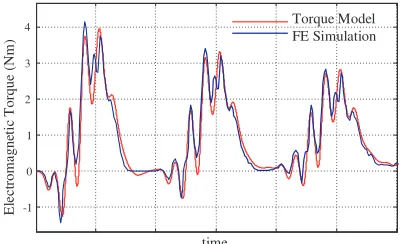
In Fig. 1, the torque response of the machine to a sinusoidal voltage excitation is shown. The nominal voltage amplitude is applied, and the transient response is plotted to show the model validity in transients until stationary operation. It is noted that the machine is designed to have minimum saturation at rated operation point. As seen on the figure, the model can help estimate the torque ripples of the machine without having to carry out Finite Element (FE) simulations that are time consuming. The use of a fast model is important to get results in a timely manner with the subsequent use of an optimization algorithm coupled with the machine electromagnetic model.
-1 0 1 2 3 4 E le c trom agne ti c T orque (N m ) Torque Model FE Simulation time
Figure 1. Comparison of torque responses due to a voltage excitation for a SynRM between the used model and FE simulations.
0.01 0.015 0.02 0.025 0.03 0.035 0.04
0 π 2π
Induc
ta
n
c
e (H)
θe (rad)
Figure 2. Phase self-inductance of a Transver-sally Laminated Anisotropic (TLA) SynRM in function of an electric angular displacement.
The equation of the average torque is given by:
Tavg =
1 2π 2π 0 1 2pI t s ∂Lss
∂θe Isdθe
(9)
The torque ripple is defined as the following:
Tripple=
max(Tem)−min(Tem)
Tavg
= ΔTem Tavg
(10)
The inductances in a machine are bi-periodic over an electric period (see Fig. 2 for a phase self inductance of a TLA rotor).
Equation (11) shows the inductance matrices of a m-phase machine.
Lss=L0+
∞
n=1
[L2nC] cos 2nθe+
∞
n=1
where
L0 =
⎛ ⎜ ⎜ ⎜ ⎝
L0aa L0ab . . . L0am
L0
ab L0bb . . . L0bm
..
. ... . .. ... L0
am L0bm . . . L0mm
⎞ ⎟ ⎟ ⎟ ⎠
L2nC =
⎛ ⎜ ⎜ ⎜ ⎝
L2aanC L2abnC . . . L2amnC
L2abnC L2bbnC . . . L2bmnC
..
. ... . . . ... L2amnC L2bmnC . . . L2mmnC
⎞ ⎟ ⎟ ⎟
⎠ (12)
L2nS =
⎛ ⎜ ⎜ ⎜ ⎝
L2aanS L2abnS . . . L2amnS
L2nS
ab L2bbnS . . . L2bmnS
..
. ... . . . ... L2amnS L2bmnS . . . L2mmnS
⎞ ⎟ ⎟ ⎟ ⎠
The m stator currents can be written under their general form as in Eq. (13). Even current harmonics do not generate torque, therefore only odd harmonics are introduced. Moreover, the order of harmonics is limited to 2N −1 for N ∈N∗.
The current amplitude of a given harmonic (H) is defined byIH, and its phase with respect to the
rotor d-axis is represented byφH.
Im=
N
k=1
I(2k−1)cos
(2k−1)
ωt−2(m−1)π
m
+φ(2k−1)
(13)
The resultant average torque is obtained by replacing Eqs. (11) and (13) in Eq. (9) and applying the synchronous condition (ωt=θe =pθm). For this purpose two non-zero average torque generating
mechanisms can be obtained in the condensed form.
Tavg = mp
2 2N−1
μ=1
m
j=1
i=1 Iμ2k
μ ijL
2μsin(2
φμ) +mp
2
2N−1
x=y
x,y=2k−1k∈N
m
j=1
i=1
IxIylxyij Lijx+ysin(Φx+ Φy)
+lxyij L
|x−y|
ij sin(Φx−Φy) (14)
Two non-zero average torque generating mechanisms can be noted from Equation (14):
(i) Theuth current harmonic generates a torque with a non-zero average value when it interacts with the inductance’s 2uth spatial harmonic. The torque can be written under the form:
Tavg(u) =
1 2mpI
2
u j=1...m
∞=1...m
kijuL2ijusin(2φu) (15)
(ii) Thexth current harmonic interacts with theyth harmonic via the two inductance space harmonics x−y and x+y and the average torque delivered by this interaction is:
Tavg(xy) =
1
2mpIxIy
m
j=1
i=1 [mxyijL
x+y
ij sin(φx+φy) +l xy ij L
|x−y|
ij sin(φx−φy)] (16)
kij,lij andmij are constants that depend on the machine phase number.
3. CASE STUDY: BI-PHASE MACHINE
(i) All odd current harmonics can be injected in contrast with the 5-phase machine where the 5th harmonic cannot be injected.
(ii) The number of required inverter legs is 4 in comparison with 5 legs for a 5-phase machine.
In this section, the average torque in the presence of current harmonics in a 2-phase machine is presented. A practical TLA design is used in order to investigate the developed model. The current fundamental and harmonics for a maximal torque per ampere are shown. Finally, an optimization study on Tripple and Tavg to determine the variables current harmonics is performed.
3.1. General Case
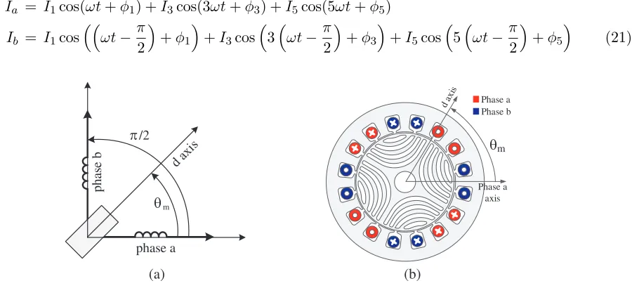
The semi-circuit representation of a bi-phase machine is shown on Fig. 3(a) and the machine cross section on Fig. 3(b). Moreover, the self inductance (Laa) can be written in its general form as in
Eq. (17). Phase b is in quadrature with respect to phasea. Therefore, self inductance Lbb is linked to
Laa by Eq. (18). Moreover,Lab is written in its general form as well in Eq. (19). The general equation of
the matrixLss is shown in Eq. (20). The developed expression of the inductance harmonic component
is limited to the 10th harmonic:
Laa=L0+L2cos(2θe) +L4cos(4θe) +L6cos(6θe) +L8cos(8θe) +. . . (17)
Lbb=Laa
θr−π
2
(18)
Lab = M0+M2sin(2θe) +M4sin(4θe) +M6sin(6θe) +M8sin(8θe) +. . . (19)
Lss=
Laa Lab
Lab Lbb
=
L0 M0
M0 L0
+
L2 0 0 −L2
cos(2θe) +
0 M2
M2 0
sin(2θe)
+
L4 0 0 L4
cos(4θe)+
0 M4
M4 0
sin(4θe)+
L6 0 0 −L6
cos(6θe)+
0 M6
M6 0
sin(6θe)
+
L8 0 0 L8
cos(8θe)+
0 M8
M8 0
sin(8θe)+
L10 0 0 −L10
cos(10θe)+
0 M10
M10 0
sin(10θe) (20)
Phase currents are limited to their 5th harmonic in Eq. (21) and the average torque is shown in Eq. (22).
Ia = I1cos(ωt+φ1) +I3cos(3ωt+φ3) +I5cos(5ωt+φ5)
Ib = I1cos
ωt−π
2
+φ1
+I3cos
3
ωt−π
2
+φ3
+I5cos
5
ωt−π
2
+φ5 (21) phase a θm pha se b π/2 θm Phase a axis Phase b Phase a (a) (b)
Tavg = p
2[I 2
1(L2+M2) sin(2φ1) + 3I32(L6+M6) sin(2φ3)
+5I52(L10+M10) sin(2φ5) + 2I1I3(−L2+M2) sin(φ1−φ3)
+4I1I5(−L4) sin(φ1−φ5) + 2I3I5(−L2− M2) sin(φ3−φ5)
+4I1I3(L4) sin(φ1+φ3) + 8I3I5(L8) sin(φ3+φ5) + 6I1I5(L6+M6) sin(φ1+φ5)] (22)
The average torque shows the respective contributions of the current fundamental and harmonics, as well as the interactions between the various harmonics as in the case of a m-phase machine. The complexity of this analytical model lies in the high interdependence of the harmonics. In other words, the variation of one parameter (IH orφH) influences many terms of the equation, and the contribution
of a current harmonic depends on the other harmonics injected in the system. In order to evaluate the model and the harmonic injection concept, the next section investigates a practical TLA SynRM.
3.2. Harmonic Injection in a TLA SynRM
3.2.1. Theoretical Aspect
The first step to evaluate the harmonic injections concept is to determine the inductance spectrum of the machine. Many attempts were made in literature to find their expression analytically in SynRMs. The most common approach is the winding theory [1, 8, 16, 19, 20] used to determine the stator inductances. In some cases, the slotting effects are taken into account [21, 23]. Furthermore, in other cases, a reluctance network is identified in order to evaluate the airgap field [22]. The airgap field can then be used to find the stator inductances. However, it is a complex task to determine the stator inductances analytically while taking into account the exhaustive non-linearities in the machine. A complete analytical method determining the inductances considering the saturation, the axes cross couplings, the slotting effect and the leakage inductances are currently non-existent. Therefore in this work, FE simulations are used instead. The TLA rotor design used is shown on Fig. 4. The flux barriers form is based on the flux lines in a solid rotor developed in [31]. The used SynRM design parameters are shown in Table 1.
The numerical values of the inductances determined by FE simulations are shown in Table 2. The inductances components aboveL2are relatively low in this geometry unlike in a simple saliency geometry [25]. Therefore, the impact of the corresponding current harmonic is negligible with respect to the fundamental. However, the 3rd current harmonic interacts with the 5th current harmonic and the fundamental spatial harmonic of the inductances as shown in Eq. (22).
2I3I5(−L2− M2) sin(φ3−φ5) (23)
This shows that for the studied SynRM geometry, the mere injection of the 3rd harmonic does not significantly contribute to the machines performances. Furthermore, two consecutive harmonics should
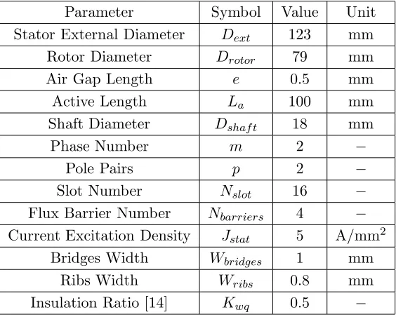
Table 1. Design parameters of the studied TLA SynRM.
Parameter Symbol Value Unit
Stator External Diameter Dext 123 mm
Rotor Diameter Drotor 79 mm
Air Gap Length e 0.5 mm
Active Length La 100 mm
Shaft Diameter Dshaf t 18 mm
Phase Number m 2 −
Pole Pairs p 2 −
Slot Number Nslot 16 −
Flux Barrier Number Nbarriers 4 −
Current Excitation Density Jstat 5 A/mm2
Bridges Width Wbridges 1 mm
Ribs Width Wribs 0.8 mm
Insulation Ratio [14] Kwq 0.5 −
Table 2. Inductance numerical values found by FE simulations for the Studied SynRM.
L0 = 2.63×10⁻²H M0 = 0 H
L2 = 1.15×10⁻²H M2 = 1.12×10⁻²H
L4 = 1.41×10⁻⁴H M4=−1.42×10⁻⁴H
L6 = 4.15×10⁻⁴H M6=−3.47×10⁻⁴H
L8=−3.34×10⁻⁴H M8=−1.91×10⁻⁴H
L10= 6.18×10⁻⁵H M10=−9.75×10⁻⁵H
be injected in order to achieve the benefit of harmonic injection. Consequently, the current harmonics considered in the following are the 3rd and the 5th harmonics. Six parameters that define the phase current shape have to be considered: (I1,φ1), (I3, φ3) and (I5, φ5). Finding the optimal values from the analytical equation of these parameters in Eq. (22) is not a straightforward task. Nevertheless, by simplifying Eq. (22), an estimate on the optimal parameters values can be obtained.
If only the two main terms of Eq. (22) are considered, Eq. (24) can be written:
Tavg = p
2[I 2
1(L2+M2) sin(2φ1) + 2I3I5(−L2− M2) sin(φ3−φ5)] (24)
It can be noted that Eq. (24) is specific to the studied machine. However, in the case of a simple saliency SynRM or a SynRM with a concentrated winding, the inductance harmonics values change, and Eq. (24) needs to be re-evaluated.
In an ideal case, the phase angle φ1 should be 45◦, and φ3 −φ5 should be −90◦ to achieve the maximal torque per ampere. If these values are considered, the simplified model gives the following:
Tavg
p
2(L2+M2)
=I12+ 2I3I5 (25)
evaluate harmonic injection. In consequence, the following constraint should be respected:
Irms2 =
I1
√
2 2
+
I3
√
2 2
+
I5
√
2 2
=
I1 max√ 2
2
(26)
In terms of current amplitude, the relation can be written as:
I12+I32+I52 =I1 max2 (27)
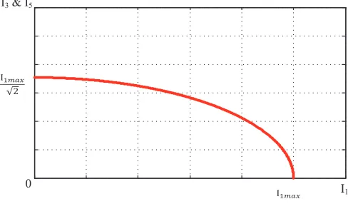
Solving Eqs. (25) and (27), the maximal torque is obtained whenI3 =I5. Moreover, the locus of the current fundamental and harmonics required to achieve a maximal torque per ampere is shown on Fig. 5.
I1
I3 & I5
0
Figure 5. Locus of the maximum torque obtained from the simplified model, forI3=I5.
3.2.2. Optimization Algorithm
An optimization algorithm is proposed in order to verify that the locus is the optimal solution taking into account a more detailed model (including a rich inductance spectrum). Since the 3rd and the 5th current harmonics are considered, the inductance spectrum used in the optimization study is limited to its 10th component as in Equation (20). The optimization algorithm uses the model to help determine the six parameters that define harmonics injection (I1, I3, I5, φ1, φ3, φ5). Two criteria are used to determine the impact of the harmonics injection on the machine performance: the average torque Tavg and the
torque ripples Tripple. From a mathematical point of view, the optimization problem is formulated as
the following:
max
I1,I3,I5,φ1,φ3,φ5 Tavg
C1 :Tripple <max(Tripple) (28)
C2:
I12+I32+I52 <10 A
In other terms, for a maximum Tripple constraint, the optimization algorithm will try to find the
maximumTavg delivered from the machine model at a constant RMS value. By varying the maximum
Tripple constraint, a pareto front could be obtained as will be seen next. The optimization procedure is
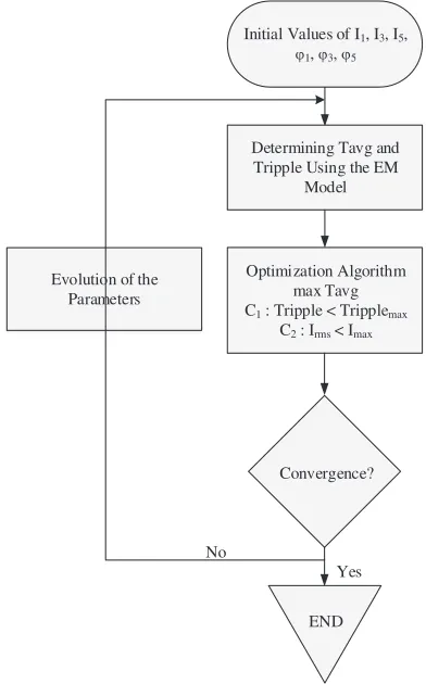
presented on Fig. 6. The chosen initial values are for the case at rated operation point without harmonics injection. Tavg andTrippleare determined using the electromagnetic model shown in Equations (8)–(10).
Afterwards, the optimization algorithm evolves the optimization variables that define the harmonics amplitudes and phase angles (I1,I3,I5,φ1,φ3 and φ5) in order to maximizeTavg while respecting the
constraints on Tripple and on the RMS current. The optimization algorithm used is the Nelder-Mead
Simplex algorithm (fminsearch in Matlab) and if the algorithm did not converge to an optimal solution, another iteration is repeated with different starting point An elementary optimization procedure (to determine one optimal point for a given max(Tripple)) requires around 200 function calls which requires
Initial Values of I1, I3, I5,
ϕ1, ϕ3, ϕ5
Determining Tavg and Tripple Using the EM
Model
Optimization Algorithm max Tavg C1 : Tripple < Tripplemax
C2 : Irms < Imax
Convergence?
END Yes No
Evolution of the Parameters
Figure 6. Optimization algorithm to determine the current harmonics parameters.
1.7 1.8 1.9 2 2.1 2.2 2.3 2.4
5 10 15 20 25 30 35
Tavg (Nm) Tri
pp
le
(%)
Without Harmonic Injection
T
ri
pp
le -4
0
%
a
t s
a
m
e
f
av
g
Figure 7. Pareto front of the Tripple in function
of Tavg for the harmonic injection optimization
algorithm.
Several runs of the optimization algorithm are performed by varying the maximumTripplefrom 0%
till 35% in order to obtain a Pareto front. For a maximalTripple below 10%, the optimization algorithm
does not deliver a solution that respects the constraint. The minimal obtained Tripple is around 10%.
The maximum limit of 35% is chosen which corresponds to the Tripple without harmonics injection
+10%. Fig. 7 shows the obtained Pareto front of Tavg in function of Tripple. The figure shows that at
a constant Irms, even by injecting harmonics, Tavg does not surpass Tavg achieved without harmonic
injection. Nevertheless, for the sameTavg, Tripple is reduced from 25% to approximately 15% (−40%).
The values ofI1,I3 and I5 that give the sameTavg and reduceTrippleare roughly the values found from
the locus shown on Fig. 5. This proves that the inductance spectrum components higher than L2 and
M2 do not significantly intervene in torque production.
3.2.3. Optimization Including Saturation
In order to take into account the saturation, numerical simulations by a FE software have been carried out. First of all, some simulations make it possible to determine the range of unsaturated operation as illustrated in Fig. 8 and the validity range of the theoretical model of the machine.
Secondly, other numerical simulations have permitted to obtain the average torque as a function of phase and rms amplitude current as described in Equation (21) in order to define lookup tables, see Figs. 9 and 10.
Figure 8. Comparison of the average torque as a function of the phase currents amplitude.
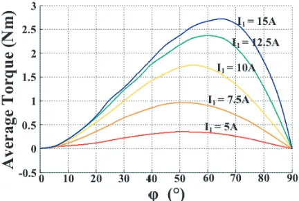
Figure 9. Average torque as a function of the current amplitude for several values of φ1.
Figure 10. Average torque as a function ofφ1 for several values of I1.
I3 =I5 in order to guarantee the maximal torque and both following equations:
I12rms+I32rms+I52rms = max(Irms)2
I12+I32+I52 = max(I1)2 (29)
Therefore, it is not necessary to know the real values of the inductances respect to the saturation of the machine.
4. EXPERIMENTAL VALIDATION
4.1. Test Bench Description
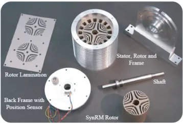
The different components of the test bench are presented on Figs. 11, 12 and 13. The controller is implemented on a DSPACE module. The DS2004 is used to acquire the data, and the DS5101 is used to generate the PWM. In order to fix the system speed, a speed-controlled MAGTROL hysteresis brake (Model HD-710) is used. The MAGTROL has an integrated torque meter of a 2 kHz bandwidth and sends the instantaneous torque as an analogue output to DSpace DS2004 to visualize the torque and to calculate Tavg and Tripple. The machine used is a lab prototype, and its performance at test speed
is shown in Table 3. The design parameters are shown in Table 1. The magnetic flux density of the machine obtained from Maxwell 2D finite elements simulation is shown on Fig. 14.
4.2. Experimental Results
Power Electronics
VDC
Phase Current Sensors
DS2004 Data Acquisition DS5101
PWM Generation
DS1005 - Micro processor
DSpace
I Angular Position
Torque Matlab/Simulink
Control Desk
I1
I2
PWM
Figure 11. Components of the test bench; DSpace is used to implement the current controller, reading the mechanical and electrical variables an generating the PWM signals; a 4-leg converter is used as power electronics.
Figure 12. Laminations and the dif-ferent constituents of the used SynRM prototype, M330-35A laminations are used for the prototype.
Figure 13. Machine prototype and the hysteresis brake.
Rib
Bridge
Figure 14. Magnetic density distribution of the studied SynRM obtained for a Maxwell 2D finite element simulations.
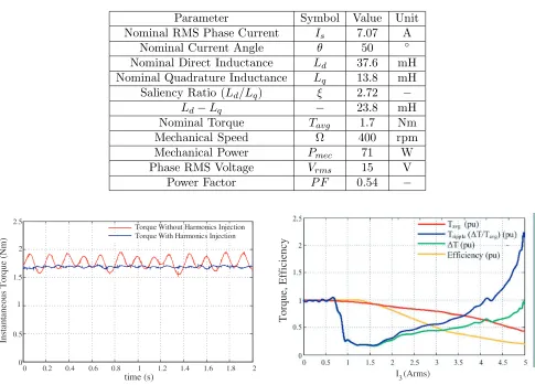
The graph shows a slight decrease of the average torque (from 1.77 Nm without harmonic injection to 1.75 Nm with harmonic injection). This is mainly due to the increase in core losses in the machine structure when injecting harmonics. Nevertheless, this decrease is negligible (∼1%).
On the other hand,Tripple decreases from 20% to 4% with harmonic injection. The optimalφ3−φ5 value is experimentally found at−135◦. The individual values of φ3 andφ5 do not impact the machine torque or the torque ripple. Note that the optimal results presented in Fig. 7 do not include the saturated operating of the machine. In these test simulations, the rated operating point is fixed to 1.7 N·m which involves the saturation of the machine. Thus, in this case, the magnitude and phase of I1 current is taken directly from Figs. 9 and 10 and the computations ofI3 andI5 with the condition I3 =I5 follow Equation (29).
On the other hand, Fig. 16 shows the Tavg, Tripple, ΔT (see Equation (10)) and the machine’s
efficiency in per units (pu) with respect to the case without harmonics injection as a function of I3rms = I5rms for the locus shown on Fig. 5. The reason for taking directly the locus values (from
Table 3. Measured performance of the SynRM prototype used in this study.
Parameter Symbol Value Unit
Nominal RMS Phase Current Is 7.07 A
Nominal Current Angle θ 50 ◦
Nominal Direct Inductance Ld 37.6 mH
Nominal Quadrature Inductance Lq 13.8 mH
Saliency Ratio (Ld/Lq) ξ 2.72 −
Ld−Lq − 23.8 mH
Nominal Torque Tavg 1.7 Nm
Mechanical Speed Ω 400 rpm
Mechanical Power Pmec 71 W
Phase RMS Voltage Vrms 15 V
Power Factor P F 0.54 −
0 0.2 0.4 0.6 0.8 1 1.2 1.4 1.6 1.8 2 0
0.5 1 1.5 2 2.5
time (s)
Ins
ta
nt
a
n
e
ous
T
orque
(N
m
)
Torque Without Harmonics Injection Torque With Harmonics Injection
Figure 15. Comparison of the torque between the case without harmonics injection (I1rms =
7.07 A, I3rms = I5rms = 0 A) and the case with
harmonic injection (I1rms = 6.93 A, I3rms =
I5rms= 1 A).
Torque, Efficiency
3
I (Arms)
Figure 16. Measured Tripple, ΔT and Tavg
of the SynRM in per unit with respect to the case without harmonics injection in function of I3 (I3 =I5).
3% which is highly favourable for AC drive applications. The constant torque is not obtained since the core losses increase in the machine due to harmonics injection. Fig. 16 shows that without fundamental current (I1rms = 0 and I3rms = I5rms = 5 A), Tavg is about 44% of the value with the fundamental
current only. However, competitive operating points, where the Tavg decreases slightly and theTripple
is around 3.5% from an initial value of 20%, are documented. Regarding the machine’s efficiency, the machine shows a slight increase (around 0.7%) prior to I3rms = I5rms = 1.25 A. After this value,
the efficiency rapidly decreases to reach 0.2 pu when the current does not contain any fundamental (I1rms= 0 and I3rms=I5rms= 5 A) as shown in Fig. 16.
Note that the machine sized in this paper does not operate at high speed. The operating range is limited to 3500 rpm.
5. CONCLUSION
The impact of the current harmonics on the average torque and the torque ripple is studied in this paper.
generation in a SynRM are formulated. The first mechanism is the proper contribution of each current harmonic, and the second is the result of the interaction between the current harmonics.
• We also show that for the studied TLA design of the SynRM the inductance harmoncis are negligible in comparison to the fundamental component. Therefore, injecting harmonics at a constant RMS current value does not allow to generate more torque. Whereas, by injecting both the 3rd and the 5th harmonics, a current harmonics locus is found that keeps the torque constant. On this locus, the torque ripple decreases significantly.
• Some laboratory results confirmed the developed model. For instance, the results also show that without impacting noticeably the average torque of the SynRM, the torque ripple can be reduced to less than 4%.
In the future work, it is planned to test the proposed model of a three-phase machine with the injection of two consecutive harmonics. This method could reduce significantly the torque ripple even in 3-phase machine.
REFERENCES
1. Al-Nuaim, N. A. and H. A. Toliyat, “A novel method for modeling dynamic air-gap eccentricity in synchronous machines based on modified winding function theory,”IEEE Trans. Energy Convers., Vol. 13, No. 2, 156–162, 1998.
2. Barcaro, M., N. Bianchi, M. Guarnieri, and P. Alotto, “Optimization of interior pm motors with machaon rotor flux barriers,” IEEE Trans. Magn., Vol. 47, No. 5, 958–961, 2011.
3. Bolognagni, S., D. Bon, P. M. Dai, and N. Bianchi, “Torque harmonic compensation in a synchronous reluctance motor,”IEEE Trans. Energy Convers., Vol. 23, No. 2, 466–473, June 2008. 4. Bolognagni, S., D. Bon, P. M. Dai, and N. Bianchi, “Rotor flux-barrier design for torque ripple reduction in synchronous reluctance and PM-assisted synchronous reluctance motors,”IEEE Trans.
Ind. Appl., Vol. 45, No. 3, 921–928, 2009.
5. Vagati, A., G. Pellegrino, E. Armando, P. Guglielmi, and B. Boazzo, “Multipolar ferrite-assisted synchronous reluctance machines: A general design approach,”IEEE Trans. Ind. Electron., Vol. 62, No. 2, 832–845, 2015.
6. Tutelea, L. N., L. Parsa, D. Dorrell, and I. Boldea, “Automotive electric propulsion systems with reduced or no permanent magnets: An overview,” IEEE Trans. Ind. Electron., Vol. 61, No. 10, 5696–5711, October 2014.
7. Xu, B., L. Cai, and H. Guan, “Low-cost ferrite PM-assisted synchronous reluctance machine for electric vehicles,” IEEE Trans. Ind. Electron., Vol. 61, No. 10, 5741–5748, October 2014.
8. Faiz, J. and I. Tabatabaei, “Extension of winding function theory for nonuniform air gap in electric machinery,” IEEE Trans. Magn., Vol. 38, No. 6, 3654–3657, November 2002.
9. Kamper, M. J., S. Gerber, and E. Howard, “Flux barrier and skew design optimisation of reluctance synchronous machines,” 2014 Int. Conf. on Electrical Machines (ICEM), 1186–1192, September 2014.
10. Ikaheimo, J., et al., “Synchronous high-speed reluctance machine with novel rotor construction,”
IEEE Trans. Ind. Electron., Vol. 61, No. 6, 2969–2975, June 2014.
11. Hsieh, M. F., H. F. Kuo, M. C. Tsai, and I. Lin, “Improved accuracy for performance evaluation of synchronous reluctance motor,” IEEE Trans. Magn., No. 99, 1–1, 2015.
12. Magnussen, F., C. Sadarangani, and R. R. Moghaddam, “Theoretical and experimental reevaluation of synchronous reluctance machine,”IEEE Trans. Ind. Electron., Vol. 57, No. 1, 6–13, January 2010.
13. Magnussen, F., C. Sadarangani, and R. R. Moghaddam, “Novel rotor design optimization of synchronous reluctance machine for low torque ripple,”20th Int. Conf. Electrical Machines (ICEM), 720–724, September 2012.
15. Ooi S., Y. Inoue, M. Sanada, and S. Morimoto, “Experimental evaluation of a rare-earth-free PMASynRM with ferrite magnets for automotive applications,” IEEE Trans. Ind. Electron., Vol. 61, No. 10, 5749–5756, October 2014.
16. Neti, P. and S. Nandi, “Determination of effective air-gap length of synchronous reluctance motors (SynchRel) from experimental data,”IEEE Trans. Ind. Appl., Vol. 42, No. 2, 454–464, March 2006. 17. Kim, S. I., J. P. Hong, J. H. Lee, and J. M. Park, “Rotor design on torque ripple reduction for a synchronous reluctance motor with concentrated winding using response surface methodology,”
IEEE Trans. Magn., Vol. 42, No. 10, 3479–3481, October 2006.
18. Hiramto, K., S. Morimoto, Y. Takeda, and M. Sanada, “Torque ripple improvement for synchronous reluctance motor using asymmetric flux barrier arrangement,” Conf. Rec. Industry Applications
Conf. 38th IAS Annu. Meeting, Vol. 1, 250–255, October 2003.
19. Schmitz, N. L., Introductory Electromechanics, Ronald Press, 1965.
20. Faiz, J., H. Lesani, M. T. Nabavi-Rzavi, and I. Tabatabaei, “Modeling and simulation of a salient-pole synchronous generator with dynamic eccentricity using modified winding function theory,”
IEEE Trans. Magn., Vol. 40, No. 3, 1550–1555, 2004.
21. Tessarolo, A., “Accurate computation of multiphase synchronous machine inductances based on winding function theory,” IEEE Trans. Energy Convers., Vol. 27, No. 4, 895–904, 2012.
22. Tessarolo, A., et al., “On the analytical estimation of the airgap field in synchronous reluctance machine,” 2014 Int. Conf. on Electrical Machines (ICEM), 239–244, September 2014.
23. Mezzarobba, M., M. Degano, and A. Tessarolo, “Analytical calculation of air-gap armature reaction field including slotting effects in fractional-slot concentrated-coil SPM multiphase machines,”Int.
Conf. Power Engineering, Energy and Electrical Drives (POWERENG), 1–6, 2011.
24. Rahimian, M., T. A. Lipo, and H. Toliyat, “DQ modeling of five phase synchronous reluctance machines including third harmonic of air-gap MMF,” Conf. Rec. IEEE Industry Applications
Society Annu. Meeting, Vol. 1, 231–237, September 1991.
25. Waikar Shailesh, P., A. Lipo Thomas, and H. A. Toliyat, “Analysis and simulation of five-phase synchronous reluctance machines including third harmonic of airgap MMF,” IEEE Trans. Ind.
Appl., Vol. 34, No. 2, 332–339, March 1998.
26. Vas, P., Electrical Machines and Drives: A Space-vector Theory Approach, Vol. 25, Oxford University Press on Demand, 1992.
27. Villet, W. T. and M. J. Kamper, “Variable-Gear EV reluctance synchronous motor drives; An evaluation of rotor structures for position-sensorless control,”IEEE Trans. Ind. Electron., Vol. 61, No. 10, 5732–5740, October 2014.
28. Wang, K., et al., “Optimal slot/pole and flux-barrier layer number combinations for synchronous reluctance machines,”8th Int. Conf. and Exhibition on Ecological Vehicles and Renewable Energies
(EVER), 1–8, March 2013.
29. Liu, T. H. and M. Y. Wei, “Design and implementation of an online tuning adaptive controller for synchronous reluctance motor drives,” IEEE Trans. Ind. Electron., Vol. 60, No. 9, 3644–3657, September 2013.
30. Xu, L., “Rotor structure selections of nonsine five-phase synchronous reluctance machines for improved torque capability,”IEEE Trans. Ind. Appl., Vol. 36, No. 4, 1111–1117, July 2000. 31. Henaux, C., M. Fadel, S. Desharnais, L. Calegari, and S. Yammine, “Synchronous reluctance
machine flux barrier design based on the flux line patterns in a solid rotor,” 2014 Int. Conf. on
Electrical Machines (ICEM), 297–302, September 2014.
32. Hock Beng Foo, G., D. M. Vilathgamuwa, D. L. Maskell, and X. Zhang, “An improved robust field-weakeaning algorithm for direct-torque-controlled synchronous-reluctance-motor drives,” IEEE
![Figure 4. Rotor design used for the proposed study; the flux barriers are based on the flux lines patternand the uniformity of the flux in a solid rotor [31].](https://thumb-us.123doks.com/thumbv2/123dok_us/1920032.1251987/6.612.249.373.567.694/figure-rotor-design-proposed-barriers-patternand-uniformity-rotor.webp)