Division 3
NUMERICAL MODELLING OF THE FATIGUE RATCHETING
FAILURE IN NUCLEAR PIPING SYSTEMS
Amin Karbassi1, Ralph Döring2, and Peter Zwicky1
1
Basler & Hofmann, Consulting Engineers, Zurich, Switzerland
2
Swiss Federal Nuclear Safety Inspectorate ENSI, Brugg, Switzerland
ABSTRACT
In pressurized piping systems, low cycle fatigue (LCF) and strain accumulation (ratcheting) can take place due to cyclic loading during a seismic event. The seismic induced failure mechanism in those systems in the design codes is mainly assumed as a plastic collapse. In reality, however, the low cycle fatigue along with incremental plastic deformations called ratcheting can lead to the failure of the piping system. The aim of this paper is to assess the ability of numerical models to predict the fatigue ratcheting failure in piping systems and components due to cyclic loading and to discuss the challenges involved. As part of an international benchmark project, organized by the Nuclear Energy Agency (NEA) along with its subgroup "Working Group on Integrity and Ageing of Components and Structures", displacement-controlled cyclic tests on a steel elbow and the dynamic tests on pipeline systems were simulated by three-dimensional nonlinear finite element models by the implicit method in ANSYS and LS-DYNA. The comparison of the results obtained from numerical analyses and the experimental measurements show that local ratcheting strains are significantly influenced by the specimen geometry, the constitutive material model and its parameters, while the global model behaviour and the strain amplitudes show a higher robustness against geometrical influences. Moreover, for the component lifetime assessment, the major damage mechanism seems to be fatigue, which is primarily influenced by the strain amplitudes.
INTRODUCTION
Comprehensive evaluation of nuclear piping systems under large amplitude seismic loads is required in order to develop rational seismic design procedures. This comprehensive assessment requires accurate prediction of inelastic response of piping systems until failure, to ensure adequate margins for unexpected beyond design basis events. In pressurized piping systems, strain accumulation can take place due to cyclic loading during a seismic event. The fatigue along with these incremental plastic deformations called ratcheting may lead to the failure of the piping systems.
Two possible failure mechanisms exist in the fatigue ratcheting regime. In the case of high mean stresses controlled by a primary load, a collapse caused by excessive strain is possible. Because of the code limitations of the primary membrane stresses to Sm (2/3 of the elastic limit or 1/3 of ultimate stress)
under normal operation conditions, the failure will occur usually by fatigue. The fatigue behaviour can be accompanied by ratcheting because (positive) ratcheting strains result in increasing true stresses caused by ballooning and wall-thinning.
The major gap in existing design codes is that fatigue has to be considered only for normal and upset but not for emergency or faulted operation conditions. Moreover, an alternative criterion to prevent failure by excessive ratcheting strains for Level C and D loading conditions of ASME III, Subsection NB would be useful. Current rules for ratcheting, based on the Bree diagram [Bree 1967] and shake-down theorem, deal only with thermal ratcheting under normal and upset operation conditions.
experimental tests of the elbow and the piping system were simulated using three-dimensional nonlinear finite element models and the implicit method in ANSYS and LS-DYNA, respectively.
DISPLACEMENT-CONTROLLED CYCLIC TESTS AT BARC
Fatigue ratcheting tests were performed on 6” stainless steel (SS304LN) elbows by the BARC (India) and the CSIR (India) [Goyal et al. 2010]. Four elbows have been filled with water and pressurized with up to 390 bar; pure quasi-static cyclic bending was applied on the elbows by subjecting them to different levels of load-line displacements. A typical elbow specimen can be seen in Figure 1 (left). For the piping system part, a three-dimensional piping system was tested under internal pressure and increasing seismic load using a shake table. The test was continued until a water jet trough a crack appeared at an elbow. The piping system can be seen in Figure 3 (left).
Figure 1. Typical elbow specimen (left) and the grid marking (right) [Goyal et al. 2010]
NUMERICAL MODEL DESCRIPTION
Numerical Model in ANSYS
The ANSYS models use fully integrated solid elements (20-nodes hexaeder, Solid186) with symmetry boundary conditions in two directions, one rigid body element for applying the external load, displacement in axial direction (UZ) and elastic-plastic analysis with a nonlinear kinematic hardening model. The internal pressure is applied on the inner surface. A negative pressure was applied on the upper end of the pipe to emulate a closed piping. The reaction forces in x-direction were checked and are numerically zero.
Figure 2. ANSYS models of the elbow
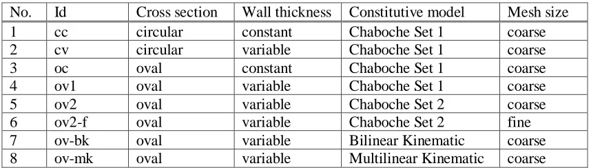
Table 1: Investigated model variants in the ANSYS model
No. Id Cross section Wall thickness Constitutive model Mesh size
1 cc circular constant Chaboche Set 1 coarse
2 cv circular variable Chaboche Set 1 coarse
3 oc oval constant Chaboche Set 1 coarse
4 ov1 oval variable Chaboche Set 1 coarse
5 ov2 oval variable Chaboche Set 2 coarse
6 ov2-f oval variable Chaboche Set 2 fine
7 ov-bk oval variable Bilinear Kinematic coarse
8 ov-mk oval variable Multilinear Kinematic coarse
Bended elbows show an ovalisation and a non-constant wall thickness. The ovalisation is implemented by an elliptic shape. The initial aspect ratio of the models with an oval cross-section is 1.105 (outer surface). This value was estimated iteratively by the calibration of the stiffness from force-displacement relationship during the linear-elastic range, because the initial ovalisation was not measured. A measured wall-thickness profil for model 2 and 4 to 8 was given and change continuously from 18.31 mm (intrados) to 11.08 mm (extrados) and was implemented by a shift between inner and outer ellipse. The results from model no. 4 were provided for the benchmark. Models 5 and 6 are improvements which were done later.
Numerical Model in LS-DYNA
The piping system is modelled using fully integrated shell elements with element formulation 16 in LS-DYNA. This shell formulation is based on Reissner-Mindlin kinematic assumption with 2x2 integration in the shell plane. This type of shell formulation is recommended for implicit simulations. A total number of 6’682 elements are used in the FE model shown in Figure 5. The base of the piping system (3 anchors) is fixed against translation and left free for rotation degrees of freedom. With the geometrical setting of the anchors, this boundary condition prevents any rotational movement for the whole structure.
Figure 3. Piping system on shake table (left) and the FE Model in LS-DYNA (right)
Material constitutive models in ANSYS
For cyclic loading, it is necessary to use constitutive models with kinematic hardening or mixed kinematic/isotropic hardening in order to model the Bauschinger effect. ANSYS provides a bilinear kinematic hardening rule (kinematic by Prager [1955]), a multi-linear kinematic hardening model by Besseling [1959] and the nonlinear kinematic hardening rule by Chaboche et al. [1979]. The model from Chaboche is a further development of the Armstrong-Frederick-Model [Armstrong and Frederick 1966] by a decomposition of the back-stress tensor in multiple parts.
(1)
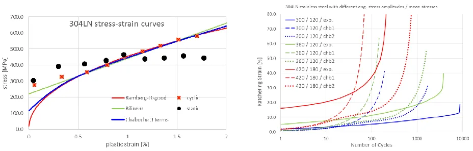
The Armstrong-Frederick model can be reproduced by choosing M = 1. All these models are used with the von Mises-yield-function and an associated flow rule. The back-stress tensor α represents the centre of the yield surface. Considering that the models with bilinear or multi-linear kinematic hardening do not reproduce ratcheting, primarily Chaboches model was used here. The Armstrong-Frederick hardening rule allows to control the ratcheting by choosing the parameter . By setting = 0, the model shows a bilinear behaviour and ratcheting rates of zero, but with higher values of , the model tends to over-estimate ratcheting. The ratcheting rates are constant for a given combination of stress amplitude and mean stress. The Chaboche hardening rule shows a more realistic behaviour with decreasing ratcheting rates at constant load level, but it tends to over-estimate ratcheting too. In this study, the Chaboche model with three decomposed back-stress terms and without the isotropic hardening option is used. Table 4 shows the two sets of parameters which have been used in the ANSYS model. The only difference is 3.
The elasticity constants used are given in references ([Goyal et. al 2013], [Vishnuvardhan et. al. 2013], [Sivaprasad et. al. 2011]) to with the modulus of elasticity E = 195 GPa and the Poisson-Ratio ν = 0.3. For the bilinear kinematic hardening model a yield stress of 220 MPa and an elastic-plastic tangent modulus of 19’770 MPa is used.
Table 2: The Chaboche model variables in ANSYS model
[MPa] [MPa] [MPa] [MPa]
CHB 1 115 35’000 300 20’000 25 2’000 1.5
CHB 2 115 35’000 300 20’000 25 2’000 0.07
Figure 4. Stress-strain-relationship (left) and ratcheting behaviour (right)
For the higher load levels, the ratcheting shows to be under-estimated; however, this seems to be caused by the interaction with the cyclic hardening/softening, especially during the first load cycle. The first loading following the static stress-strain-curve, shows a more flat characteristic and results in an initial ratcheting strain of around 17 %. This complex cyclic hardening/softening behaviour cannot be predicted by the Chaboche model. The feature implemented in ANSYS to combine kinematic hardening with isotropic hardening allows a shift of the yield stress only, which does not seem to be useful.
A model developed by one of the authors of this paper [Döring 2003], should be able to predict this behaviour more accurately. This model, however, has not yet been used because of the time consuming parameter identification. Another disadvantage of the above mentioned models is that they are not provided by the available commercial software; therefore, they have to be applied as a user-defined material subroutine.
Material constitutive model in LS-DYNA
The material model used in the FE analyses for the piping system in the LS-DYNA model is the Plastic Nonlinear Kinematic called MAT_165 in LS-DYNA. This relatively simple model, based on a material model by Lemaitre and Chaboche [1990], is suited to model nonlinear kinematic hardening plasticity. The model accounts for the Bauschinger effect, linear cyclic hardening, and ratcheting. By neglecting the isotropic hardening it is compatible with the models in [Chaboche et al. 1979] (one backstress) and [Armstrong and Frederick 1966]. The constitutive model is available for shell and solid elements. Based on a comparison with the stabilized stress-strain curve for SS 304LN, the isotropic plastic hardening modulus H, the kinematic hardening modulus C, and kinematic hardening parameter Gamma, are set to the values shown in Table 3.
Table 3: The material variables used in the FE model
H [MPa],
Isotropic plastic hardening
C [MPa], Kinematic hardening
Gamma, Kinematic hardening
[MPa]
0 12’000 1.0 220
NUMERICAL ANALYSIS RESULTS
Elbow Model in ANSYS
Figure 5: Radial displacement during first load cycle (left) and history of ovalisation (aspect ratio, right)
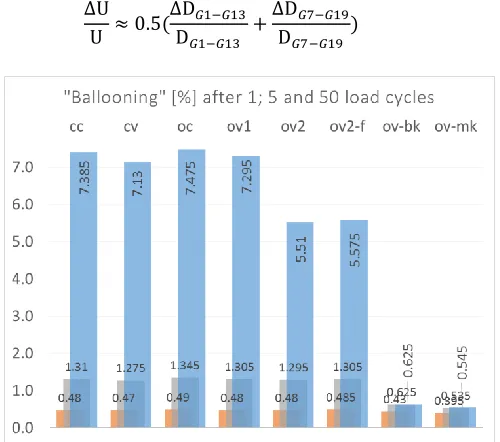
Figure 6 shows the influence of the cyclic loading on the so called ballooning defined in this paper by the change in the circumference ( ). From FE model in ANSYS, this value was determined using the displacements and a numerical integration procedure of all nodes at the path. A good approximation is the arithmetic mean of the diameters from intrados to extrados and from crown to crown, shown in Eq. 2. The experimental data provide only the diameter from intrados to extrados, so the ovalisation and the
ballooning are not distinguishable.
(2)
The ballooning shows low dependency from the geometry. Effects of mesh size are also negligible. This value is primarily influenced only by the ratcheting behaviour of the constitutive model. Bigger differences among model variants in Table 1 are detected through analysing the local strains. The scatter of the results covers a range of around factor two for the ratcheting strains. The bi- and multilinear kinematic hardening models do not show ratcheting. The strain amplitudes of all models are much closer to each other than the absolute strains and are in acceptable agreement with the experimental results.
The most interesting positions are the crown and the intrados position with the highest strain amplitudes and extrados position which also show significant ratcheting strain in hoop direction (Figure 7). The calculated hoop and axial strains at the crown (Figure 8) have good agreements with the experimental results. Ratcheting strains at the extrados position (Figure 9) were calculated with positive values by all model variants, while the experimental results do not show ratcheting.
Figure 7: Total hoop strain (left) and total axial strain (right) after 50 load cycles
Figure 8: Hoop strain (left) and axial strain (right) at crown position (G07)
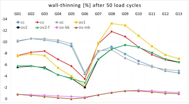
The ratcheting strains correlate well with the wall thinning, shown in Figure 10. The driving force for ratcheting is the cyclic plasticity in combination with mean stresses, here the primary stresses caused by the internal pressure. The absolute maximum of the equivalent plastic strain amplitude is on the outside of intrados (G1) and local maxima with similar amplitudes are at the crown (G7) inside, further local maxima at intrados (G1) inside and near crown (G8) outside. The strain and stress amplitudes or ranges are considered as the most important results for the structural integrity assessment.
Figure 10: Wall-thinning after 50 load cycles
At the extrados position, a high influence from the geometry is visible. A significant influence factor on the strain amplitudes, however, is the stress-strain curve used for the material model. The calculation with the bilinear kinematic hardening (not shown) model results in slightly higher plastic strain amplitudes but no ratcheting. By the fact of displacement controlled testing for these specimen the dependencies from material model on the strain response are limited. In case of force controlled testing there could be a significant stronger effect.
Piping System Model in LS-DYNA
The results of the modal analysis are shown in Table 4. As seen from the results, the natural frequencies and the Eigen modes of the first three modes are in good agreement with the values reported from the sine sweep test.
Table 4: Modal frequencies and cumulative mass fractions of the piping system
Mode LS-DYNA
Frequency (Hz.)
Test frequency (Hz.)
Cumulative mass fraction X (%)
Cumulative mass fraction Y (%)
Cumulative mass fraction Z (%)
1 3.8 3.5 1.1 0.0 73.7
2 5.9 5.5 1.1 78.8 73.7
3 12.4 15 1.1 79.5 73.7
4 18.8 - 86.2 79.5 74.1
5 28.4 - 86.2 82.8 74.1
Figure 11: Axial strain time history at extrados D section for test S04 (above) and test S05 (bellow)
At the higher table accelerations, the numerical model of the pipe system in LS-DYNA tends to overestimate the strain accumulation in critical areas. This strain accumulation generally starts earlier in the numerical calculations than in the experimental case. For the highest accelerations with significant levels of plasticity, numerical instabilities were observed.
CONCLUSIONS
Some results, like local ratcheting strains are significantly influenced by the specimen geometry (ovalisation, wall thickness). The global model behaviour (axial reaction forces, ballooning) and the strain amplitudes show a higher robustness against geometrical influences. Ballooning should be distinguished from ovalisation. To this end, ballooning is defined here as the change of circumference. With this definition, ballooning can be approximately calculated using the mean of the two diameters intrados-extrados and crown-crown.
ACKNOWLEDGMENT
The authors are grateful for the data provided by the BARC and CPRI research centres. They also wish to express their gratitude to the organizers of the MECOS Benchmark project.
REFERENCES
Bree, J., Elastic-Plastic Behaviour of Thin Tubes Subjected to Internal Pressure and Intermittent High-Heat Fluxes with Application to Fast-Nuclear-Reactor Fuel Elements, Journal of Strain Analysis, V2 N3, 1967
Sumit Goyal, Suneel K. Gupta, Vivek Bhasin, K. K. Vaze, A. K. Ghosh, S. Vishnuvardhan, M. Saravanan, D.M. Pukazhendhi, P. Gandhi and G. Raghava, Fatigue Ratcheting Investigation on Pressurised Elbows made SS304LN, Proceedings of ICTACEM 2010.
W. Prager: The theory of plasticity: A survey of recent achievements. In Proceedings of Inst. Mech. Engineers, volume 169, pages 41-57, 1955.
J.F. Besseling: A theory of elastic, plastic and creep deformations of an initially isotropic material showing anisotropic strain hardening, creep recovery and secondary creep. Trans ASME Journal of Applied Mechanics, 25: 529-563, 1959.
J.L. Chaboche, K. Dang Van and G. Cordier: Modelization of the strain memory effect on the cyclic of 316 stainless steel. In 5th Int. Conf. Struct. Mech. in Reactor Techn., volume Div. L, page L11/3, 1979
P.J. Armstrong and C.O. Frederick: A mathematical representation of the multiaxial bauschinger effect. Technical Report RD/B/N 731, Central Electricity Generating Board, 1966.
Sumit Goyal et. al., Low Cycle Fatigue and Cyclic Plastic Behavior of Indian PHWR/AHWR Primary Piping Material, Proceedings of 6th Int. Conf. on Creep, Fatigue and Creep-Fatigue Interaction, pp. 136 – 143, 2013
S. Vishnuvardhan et. al., Ratcheting Strain Assessment in Pressurized Stainless Steel Elbows Subjected to In-plane Bending, Proceedings of 6th Int. Conf. on Creep, Fatigue and Creep-Fatigue Interaction, pp. 666 – 670, 2013
S. Sivaprasad et. al., Cyclic Plastic Deformation Behaviour of PHT Piping Materials – An Experimental Investigation”, SMiRT 21, Paper ID#512, 2011
R. Döring, J. Hoffmeyer, T. Seeger and M. Vormwald: A plasticity model for calculating stress-strain sequences under multiaxial nonproportional cyclic loading. Computational Materials Science, 28(3-4): 587 - 596, 2003.
![Table 2: The Chaboche model variables in ANSYS model [MPa] [MPa] [MPa] [MPa]](https://thumb-us.123doks.com/thumbv2/123dok_us/1611989.1199817/4.612.71.493.67.180/table-chaboche-model-variables-ansys-model-mpa-mpa.webp)