NONLINEAR ANALYSIS RULES COMPARISON
BENCHMARK AND FIRST RECOMMENDATIONS
Claude Faidy1, Andrew Wazylik2
1 Consultant, Structural Integrity Mechanical Engineer, AFCEN, France 2 Mechanical EngineeringProject Manager, WNA-CORDEL, UK
ABSTRACT
During the past 30 years the main rules to design pressure vessels were mainly based on elastic approaches. Many conservatisms associated to different elastic approaches are shortly presented in the paper, like: stress criteria linearization for 3-D components, stress classification in nozzle areas, plastic shake down analysis, fatigue analysis, Ke evaluation, and piping stress criteria for elastic follow-up due to thermal expansion or seismic loads…
This paper will supplement previous paper on review of existing non-linear codified rules in nuclear and non-nuclear Codes that are proposed as alternatives to elastic evaluation for different failure modes and degradation mechanisms: plastic collapse, plastic instability, tri-axial local failure, fatigue and Ke, plastic shakedown. These methods are based on limit loads or elastic-plastic analyses.
The Code comparison considered vessels and piping systems. No existing Code is sufficiently detailed to be easily applied; the needs are based on stress analysis methods through finite elements, material properties including material constitutive equations and criteria associated to each methods and each failure modes.
To conclude, a first set of recommendation to perform these inelastic analyses will be presented to improve existing codes on an international harmonized way, associated to all material properties and criteria needed to apply these modern methods.
These rules proposal is associated to 2 typical international benchmarks: one large ferritic vessel nozzle under pressure and piping loads and one piping stainless steel nozzle under thermal shocks cycling loads. These benchmarks will compare elastic, elastic-plastic or limit load methods on realistic practical cases. The first results confirm some conservatism of elastic approaches and the benchmarks are very important tools to define final non-linear analysis codified rules.
INTRODUCTION
Many Pressure Vessel and Piping Codes, nuclear and non-nuclear, consider “non-linear analyses” at design level as an alternative to linear elastic basic codified approach. One of the major advantages is to limit the discussion on this complex concept of “stress classification in primary versus secondary”. This stress classification can be simple in many cases (shell or beam elements), but can be more complex in a lot of cases (nozzle area or seismic loads…), and in some cases the elastic analysis result can be un-conservative.
Some other applications of the “non-linear analyses” are connected to cyclic loads: plastic shakedown, fatigue analysis, seismic loads or other dynamic cyclic loads.
The codes consider in this report are:
- Nuclear Codes with English version available: RCCM, RCC-MRx, ASME Boiler & Pressure Vessel Code Section III and KTA German Code,
- Nuclear Codes with available information in literature (but no English Code Edition available): JSME Pressure Vessel Code, Russian Nuclear Codes and R5 Rule (not strictly a Code)
- Non-nuclear Codes: ASME Boiler & Pressure Vessel Code Section VIII and EN 13445 European Standard.
Three major failure modes considered:
- excessive deformation or plastic collapse - plastic instability
- buckling
Two major degradation mechanisms are considered: - Fatigue (Ke, K…) and cycle by cycle evaluation - Plastic shakedown
Other applications are proposed in some Codes for:
- Stress classification and elastic follow-up in particular for piping systems Three types of loads are considered:
- monotonic loads - cyclic loads
- seismic dynamic-cyclic loads (generally associated to specific rules for piping) Final report organisation:
- Part 1: Code Comparison and Open points - Part 2: Recommended practice document - Part 3: Benchmarks
This paper reviews the status of the "Recommended Practice Document" that makes a set of proposals for a harmonized Code Case that will be managed by each Code Organization. 3 examples of "Recommended Practices are presented, the others that needs complex material constitutive equations are on the finalization process.
OPEN POINTS IN THE DIFFERENT CODES
The Code comparison done in Part 1 (Tables 5 and 6) is associated to a set of "Open points" to be solved in the "Best Practice Document" (part 2 of the Project):
- Tresca versus Von Mises plasticity criteria and need of correction factor on limit load, - No guidance for the use of Finite Element Analysis (FEA) for limit load evaluation
- Limits on the use of limit analysis for level D criteria (possible large displacement) and flow stress value,
- Detailed recommendations for analysis, as:
o Temperature to use for each step of these analyses
o Tolerances and precise geometry to perform inelastic analysis
o More general FEA recommendations (mesh refinement, small versus large displacement, convergence criteria…)
o Cyclic elastic-plastic analyses for fatigue and shakedown
o Strain criteria for elastic-plastic analysis; the criteria have to be in the Code and can be modified case by case by the user’s design specification.
o Local failure requirements: in level D or through elastic-plastic analysis
o All the material properties for all these analysis (engineering/ true and cyclic stress-strain curves, material constitutive equations…)
o K, Ke and Kn factors: optimization and associated justification of simplified elastic-plastic analysis
o Cyclic elastic-plastic analyses for fatigue and shakedown needs more detailed procedure
CONCLUSION ON CODE COMPARISONS
All codes define limitations to justify component failure margins from the application of operation mechanical or thermal loads.
The failure mechanisms which are accounted for are the following (Table 1): - excessive deformation (plastic collapse)
- plastic instability
- local failure (decohesion)
- the degradation mechanisms considered, generally associated to cyclic loading are (Table 2): - progressive deformation induced by repeated loads (ratchetting/shakedown)
- fatigue
Some Codes consider the damage mechanism connected to stress triaxiality: local failure by decohesion, clarification of background and needs of alternative nonlinear rules is required.
All the Codes considered in this report have to be strongly improved in order to assure clear and precise use of different types of non-linear analysis, be more efficient for some particular case and take benefit for less conservative rules than elastic analysis.
The different non-linear analyses are:
- limit analysis associated to elastic perfectly plastic material; the corresponding criterion are based on load comparison
- monotonic elastic-plastic analysis associated to material stress-strain curve; the corresponding criterion are based on a maximum strain level (sufficiently low compared to material maximum elongation)
- cyclic elastic plastic analysis associated to material cyclic stress-strain curve for fatigue plasticity correction factor or more sophisticated material constitutive equation for shakedown and ratchetting analysis
Some other applications of non-linear analysis are associated to "stress classification" improvements and alternative rules, like:
- pipe / nozzle neck area,
- piping systems thermal expansion stress classification (elastic follow-up) - piping systems under seismic loads, in particular for high level seismic event
The review of all the existing Codes and existing non-linear analysis design rules [11] are key issue to start, develop the “best practice document” (Report Part 2), associated to detailed procedure proposals and validation- background at each level of the procedures.
PRELIMINAY PROPOSALS FOR THE BEST PRACTICES DOCUMENT
The scope of the document will cover:
- Components: Vessel, piping; class 1and class 2
- Failure Modes: Plastic collapse, Instability, Local Failure - Degradation mechanism: fatigue, plastic shakedown
- Analysis Methods: Non-linear analysis (limit analysis and elastic plastic) - Loads: monotonic, cyclic, dynamic
- Type of loads: mechanical (dead weight, pressure…), thermal (thermal expansion, thermal gradient transients), seismic
- General Quality Management: Requirements for Computer Codes and Analysts
The next part of the report will develop methods, criteria and all the material properties needed to perform the different analysis for: plastic collapse, plastic instability, local failure, fatigue and plastic shakedown. For plastic collapse, two methods will be proposed: plastic limit load with the material yield strength or an elastic-plastic analysis with "double –slope" criteria.
For plastic instability, one method using elastic-plastic analysis with strain criteria and another one (not completely theoretically valid) based on limit load with a flow stress equal to half the yield strength plus maximum strength of the material. Some particular attention will have to consider possible large displacement of some structures.
For fatigue two ways will be proposed: one by simplified direct plastic analysis of Ke with cyclic stress-strain curve and kinematic hardening the other one directly connected with the plastic shakedown analysis by direct cycle by cycle analysis and dedicated plasticity laws for the material (mixed hardening laws…). For plastic shakedown a direct elastic perfectly plastic analysis could be a first step approach.
DEFINITIONS
Plastic Analysis
Plastic analysis is that method which computes the structural behaviour (stress, strain, displacement…) under given loads considering the plasticity characteristics of the materials, including strain hardening and the stress redistribution occurring in the structure.
Plastic Analysis and Collapse Load
A plastic analysis may be used to determine the collapse load for a given combination of loads on a given structure. The following criterion for determination of the collapse load shall be used:
- a load–deflection or load–strain curve is plotted with load as the ordinate and deflection or strain as the abscissa. The angle that the “linear part of the load– deflection or load–strain curve” makes with the ordinate is called .
- a second straight line, hereafter called the “collapse limit line”, is drawn through the origin so that it makes an angle = tan-1(2 tan ) with the ordinate.
The collapse load is the load at the intersection of the load–deflection or load–strain curve and the collapse limit line. If this method is used, particular care should be given to ensure that the strains or deflections that are used are indicative of the load carrying capacity of the structure.
Plastic Instability Load
The plastic instability load for areas under predominantly tensile (or compressive) loading is defined as that load at which unbounded plastic deformation can occur without an increase in load. At the plastic tensile instability load, the true stress in the material increases faster than strain hardening can accommodate.
Limit Analysis
Limit analysis is a special case of plastic analysis in which the material is assumed to be ideally plastic (non-strain-hardening). In limit analysis, the equilibrium and flow characteristics at the limit state are used to calculate the collapse load. The two bounding methods which are used in limit analysis are:
- the lower bound approach, which is associated with a statically admissible stress field,
- and the upper bound approach, which is associated with a kinematically admissible velocity field. For beams and frames, the term "mechanism" is commonly used in lieu of "kinematically admissible velocity" field.
Limit Analysis and Collapse Load
The methods of limit analysis are used to compute the maximum load that a structure assumed to be made of ideally plastic material can carry. At this load, which is termed the “collapse load”, the deformations of the structure increase without bound.Collapse Load — Lower Bound
Plastic Hinge
A “plastic hinge” is an idealized concept used in Limit Analysis.
In a beam or a frame, a plastic hinge is formed at the point where the moment, shear, and axial force lie on the yield interaction surface.
In plates and shells, a plastic hinge is formed where the generalized stresses lie on the yield surface.
FAILURE MODE AND DEGRADATION MECHANISMS
Local failure (decohesion)
In all location in the vessels, including nozzle areas, in level A-B-C the stress triaxiality has to be limited.
Fatigue
Simplified elastic plastic analysis: Ke
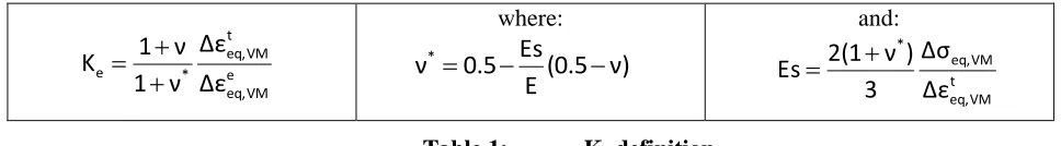
Ke, as defined in Table 1, represents the plastic strain amplitude amplification for a given cyclic load with elastic stress amplitude greater than 2 times the material yield strength. It’s used to correct the elastic strain amplitude: t = Ke . el. It can be “global” covering all cyclic plasticity effects, or a more accurate definition can be used, as:
where: and:
Table 1: Ke definition
with:
- t eq,VM: total equivalent Von Mises strain amplitude - : Poisson ratio
Different simple assumption are proposed in different Pressure Equipment Codes, as: ASME BPVC-Section III and VIII, RCC-M, RCC-MRx, JSME, Russian PNAEG Code or EN 13445- Clause 18. The key added material property data required is as a minimum: the cyclic stress-strain curve ().
Some of these formulae are “empirical” and based on a set of finite element analysis of typical cases with a bilinear cyclic stress-strain curve. A conservative “best fit curve” is proposed in the Code rules. The formal validation of this type of rules is associated to the cases considered in term of geometry, loads and material data…
Direct strain range evaluation: t/2
The alternative is to move to a “direct strain range” evaluation on few cycles, with an extrapolation rules if necessary.
In any case, the plastic shakedown of the structure and location has to be “justified”. Plastic shakedown analysis (constant stabilized strain amplitude after few cycles) has to be performed in the same time.as plastic shakedown and ratcheting analysis.
Many international projects are ongoing in different international groups. It’s a complex problem associated to dedicated material constitutive equation to be used for the material and the corresponding finite element analysis.
A cumulative strain amplitude limit has to be defined for level A criteria.
PLASTIC COLLAPSE
General Analysis Methods
o Limit analysis
o Elastic plastic analysis e VM eq, t VM eq, * e
Δε
Δε
ν
1
ν
1
K
(0.5
ν)
Material properties
For limit analysis
- Thermal / Mechanical material properties
o Basic codified mechanical and thermal properties o Young Modulus versus temperature: E
o Sflow = Sy(Rp0.2) versus temperature
o Elastic-perfectly plastic stress-strain curves with E' = E/100 - Plasticity models / Constitutive equations
o Von Mises
o Isotropic hardening For elastic-plastic analysis
- Engineering stress-strain curve versus temperature
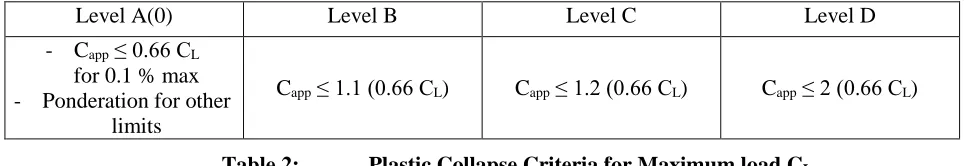
Criteria based on maximum load or double-slope load CL (Table 2)
Level A(0) Level B Level C Level D
- Capp ≤ 0.66 CL for 0.1 % max - Ponderation for other
limits
Capp ≤ 1.1 (0.66 CL) Capp ≤ 1.2 (0.66 CL) Capp ≤ 2 (0.66 CL)
Table 2: Plastic Collapse Criteria for Maximum load CL
Practical recommendations for CL evaluation For limit analysis
- Initial geometry / Small displacement
- Flat stress-strain elastic plastic bilinear curve: E' = E / 100 - Von Mises
- Material properties: Rp0.2 or Sy - Material property limitation: Su / Sy - Temperature effects on material properties - Finite Element Analysis (FEA):
o Mesh refinement: not too large o Convergence criteria: sufficiently low o End of calculation: non convergence point - Loads:
o define a representative load in the elastic regime, o and multiply it by (proportional loads)
o No functional capability requirement can be considered o Result analysis based on maximum load CL
o Sensitivity analysis
For monotonic elastic-plastic analysis - Initial geometry / small displacement
- Elastic plastic engineering stress-strain curve
- Stress-strain curve maximum strain slightly over the maximum strain considered in the analysis - Von Mises plasticity criteria
- Finite Element Analysis (FEA) :
o mesh refinement: sufficiently refined, not necessary too much in stress concentration areas o convergence criterion: reasonably low
o model with elastic sub-part - Loads:
o Functional capability requirement can be taken into account through specific requirements defined in the design specification (strain, stress or displacement limitations)
- Result analysis based on "double- slope" criteria to determine CL - Sensitivity analysis
PLASTIC INSTABILITY
Analysis Methods
- Limit analysis (with particular precaution) - Elastic plastic analysis
Material properties
- For limit analysis
o Thermal / Mechanical material properties
Basic codified mechanical and thermal properties Young Modulus
Monotonic engineering stress-strain curve Sflow = (Rp0.2 + Rm) / 2
o Plasticity models / Constitutive equations Von Mises plasticity criteria
Isotropic hardening - For elastic-plastic analysis
o Codified Thermal / Mechanical
o Basic codified mechanical and thermal properties o Young Modulus versus temperature: E
o Monotonic true stress-strain curves
Criteria based on maximum load or specified maximum strain load CI (Table 3)
Level A(0) Level B Level C Level D
Capp ≤ CI / 1.5 Capp ≤ CI / 1.5 Capp ≤ CI / 1.2 Capp ≤ CI / 1.1
Table 3: Plastic Collapse Criteria for Maximum load CI
Practical recommendations for CI evaluation For limit analysis
- Initial geometry / Small and large displacement - flat stress-strain curve E' = E /100
- end of calculation: small slope of load line displacement curve - mesh refinement: not too much refine in stress concentration areas - no functional capacity requirement
- material properties: Rp0.2, Rm
- Sensitivity analysis: compare large versus small displacement results to assure that final geometry is closed to the initial one
- Temperature effects
- Von Mises plasticity criteria
For elastic-plastic analysis monotonic
- Elastic plastic engineering stress-strain curve
- Stress-strain curve extrapolation largely over maximum strain criteria - Von Mises plasticity criteria
- Strain hardening: isotropic
- End of calculation: over the maximum strain criteria (codified or specified in the Design Specification
- Finite Element analysis (FEA) :
o convergence criterion: sufficiently low o element of FEA:
mesh refinement: not too much in stress concentration areas possible elastic sub-part
- Loads:
o Proportional load for limit analysis, all loads for elastic-plastic analysis
o Functional requirement can be taken into account through specific requirements in the design specification (strain, stress or displacement limitations)
- Result analysis based on CI estimation - Sensitivity analysis
FATIGUE
Fatigue Analysis Methods proposed
- Simplified elastic-plastic analysis through Ke - Direct strain amplitude evaluation : tot / 2
For Simplified elastic-plastic analysis
Thermal / Mechanical Material properties
- Basic mechanical and thermal material properties - Young Modulus E versus temperature
- Cyclic stress-strain curves versus temperature Plasticity models / Constitutive equations - Kinematic hardening
- Von Mises
Ke definition
- See previous paragraph for definition of Ke
Practical recommendations for Ke evaluation
For Ke evaluation use a multi-linear cyclic stress-strain curve as a monotonic stress-strain curve up to 3 times the yield strength of the material
For direct evaluation of the strain range
More complex material constitutive equations are needed to evaluate step time after step time t % as defined in previous paragraph. The corresponding work is on-going and not covers in this paper.
BENCHMARKING OF THESE DIFFERENT METHODS
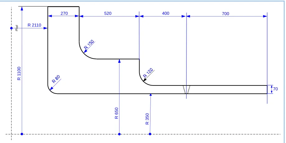
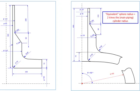
The 3rd part of the Project will be attached to two typical geometries for international benchmarks:
- One low alloy steel large component nozzle under pressure and piping loads using bi and tri-dimensional geometry models for plastic collapse, plastic instability and stress classification analyses (Figure 1),
CONCLUSION
This Project is organized around for Tasks: - International Codes comparison - Recommended practices document - Benchmarking of the different methods - Draft Code Case
The Code comparison confirms a need of international harmonized rules, associated with: - validity limits and recommendation to users
- detailed step by step methods, with criteria and all material data needed to perform these analyses - quality management requirement for Computer Codes and analysts.
All the project is continuously in touch with the different Code organizations, like ASME, AFCEN, JSME, KEPIC and NIKIET, for regular review of the different documents.
A dedicated international Code Case can be a possible way to finalize the results; each Code organizations will be free to manage the use of this Code Case in its own Code.
ACKNOWLEDGEMENTS
The Author will thank WNA-CORDEL-CSTF for its support and the regular reviewers of the different documents: Seiji Asada (JSME), Andrey Obushev (NIKIET), Karl Herter (MPA Stuttgart), Robert Ainsworth (Manchester University), Robert Keating (ASME-USA), Wolf Reinhart (ASME-CANADA), Denis PONT (EDF-SEPTEN), Cécile Petesch (CEA), Hoon-Seok Byun (KEPIC) and AFCEN-RCC-M and RCC-MRx Design Groups.
REFERENCES
RSE-M Code, "Rules for In-service Inspection of Nuclear Power Plant Components", AFCEN RSE-M 2016 Edition
RCC-MCode:Design and Construction Rules for Mechanical Components of PWR Nuclear Island, AFCEN 2016 Edition
ASME Boiler & Pressure Vessel Code, Section III - Rules for Construction of Nuclear Facility Components, ASME 2015 Edition
RCC-MRx: Design and Construction Rules for Mechanical Components of Nuclear Installations, AFCEN 2015 Edition
KTA: Safety Standards of Nuclear Safety Standards Commission; KTA 3201.2 Components of the Reactor Coolant Pressure Boundary of Light Water Reactors, Part 2: Design and Analysis, Edition 2010
JSME Code: JSME nuclear codes and standards for design and operation of domestic nuclear power plant facilities, Edition 2010 (in Japanese, use of Literature Articles)
KEPIC Code: Korea Electric Power Industry Code, Edition 2010 (in Korean)
PNAEG: Standards to the Tensile Strength of Equipment and Pipework at Nuclear Power Plants, PN.6X-G7-002-86, 1986 Edition (in Russian)
R5 Rule: procedures for assessing structural integrity of components under creep and creep–fatigue conditions, EDF Energy 2010 Edition
ASME Boiler & Pressure Vessel Code, Section VIII: Rules for Construction of Pressure Vessels - Division 2: Alternative Rules, ASME 2015 Edition
EN 13445: Unfired pressure vessels European Standard, Part 3: Design, 2009 Edition
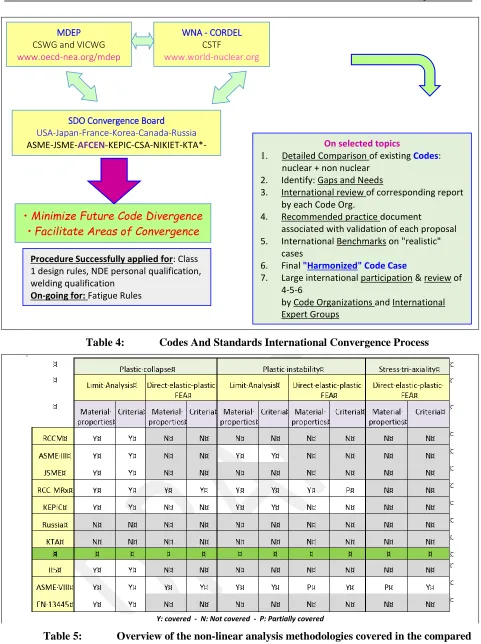
Table 4: Codes And Standards International Convergence Process
Y: covered - N: Not covered - P: Partially covered
Table 5: Overview of the non-linear analysis methodologies covered in the compared codes for MONOTONIC loading
MDEP CSWG and VICWG
www.oecd-nea.org/mdep
WNA - CORDEL CSTF
www.world-nuclear.org
SDO Convergence Board USA-Japan-France-Korea-Canada-Russia
ASME-JSME-AFCEN-KEPIC-CSA-NIKIET-KTA*-China*
• Minimize Future Code Divergence • Facilitate Areas of Convergence
Procedure Successfully applied for: Class 1 design rules, NDE personal qualification, welding qualification
On-going for: Fatigue Rules
On selected topics
1. Detailed Comparison of existing Codes: nuclear + non nuclear
2. Identify: Gaps and Needs
3. International review of corresponding report by each Code Org.
4. Recommended practice document
associated with validation of each proposal 5. International Benchmarks on "realistic"
cases
6. Final "Harmonized" Code Case
7. Large international participation & review of 4-5-6
Y: covered - N: Not covered - P: Partially covered
Table 6: Overview of the non-linear analysis methodologies covered in the compared codes for CYCLIC loading
R
1
100
R 2110
270
R
650
R
350
70
520 400 700
500
115
85
70
210
700
200
80
220
400
115
85
70
210
80
220
θ= 90 º
"Equivalent" sphere radius = 2 times the (main piping)
cylinder radius