A Control Topology to Magnify VSC Coupled
Weak Grids Performance with Self-
Synchronization Capability
Valluri Aravind 1, A. Durga Prasad2
P.G. Student, Department of Electrical & Electronics Engineering, Sir C.R.Reddy College of Engg., Eluru, India1
Assistant Professor, Department of Electrical & Electronics Engineering, Sir C.R.Reddy College of Engg., Eluru, India2
ABSTRACT: This paper scrutinize a new course of scenario for a weak grid is to make possible the interfacing of voltage source converters (VSCs) more adequate and to enhance performance of weak grid by damping power and frequency oscillations. To mitigate power and frequency oscillations, a linear controller and non-linear controller is used based on droop characteristics. Here the non-linear controller has cascaded angle, power loops for frequency and angle regulation. The controller provides new control tactic for VSC to damp power and frequency oscillations by accordingly synchronizing the VSC to grid. The linear controller can also be applicable for both islanded and grid connected operation without reconfiguration. The controller endeavours a steady and invariable operation. And also investigation was carried out on system performance at low and high-power references, transition to islanding, self-synchronization. Simulation of the recommended controller was simulated in MATLAB/SIMULINK software. The Secured Simulation results validate that the proposed non-linear controller intensifies the system under unusual disturbances and shows the impressive working of the controller.
KEYWORDS:Distributed generation, linear control, Power damping, Voltage source converter (VSC), Weak grid.
I. INTRODUCTION
Fig.1. System Model of a grid-connected VSC
The above Fig.1 shows the configuration of the simulated system. The system is composed of a 7.0 MW VSC, filter, local load, transformer and an interface line connecting the VSC to a grid. It is worth to mention that the impedance is the equivalent impedance of the stiff source referred to the distribution level.
II. PROPOSED SCHEME
This paper mainly focuses on improvement of non-linear power damping controller to integrate VSC’s to weak grids. It has linear power-damping/ synchronizing controller and non-linear power damping controller. The reference
frequency (ωset) in the frequency loop is set equal to the grid frequency and the VSC gives the reference power (Pset)
in steady state conditions.
The balanced real power is analysed by the following
= + ( − cos ) (1)
The above equation states that the real power that can be emitted from a VSC is margined. And the SCR capacity cab be determined as follows
= (2)
Where short circuit capacity (Ssc) is given by
= (3) Z is the circuit equivalent Thevenin impedance. This implies that the weaker the grid, the lower the power transfer capacity of the line. In a weak grid with, the theoretical maximum power transfer capacity is 1.0 p.u.
To get rid of the switching effect superimposed on real power, a low-pass filter can be added and purified power is passed to the controller. The power damping control law for a VSC is proposed as follows:
∆ =− ( − )− − ( − ) (4)
operation and under several transient conditions is eliminated. The damping and the synchronizing power components are expressed as
Damping power = ∆ =− (5) Synchronizing power = ∆ =− ∆ (6) It is important to take into account that the VSC’s frequency and angle are internally available; therefore, there is no need for a PLL in steady-state operation and several transient conditions.
Fig.2. Control Topology for Output Voltage Control P-V Bus. Fig.3. Control Topology for Output Voltage Control P-Q Bus
It provides different control strategy for output voltage to PV and PQ bus. It is shown in Fig.2. Fig.3 also, it has a voltage amplitude controller which provides specific control depending on type of bus.. the angle and frequency loops provide synchronizing and damping power components for the VSC to track frequency and angle deviations of the grid and automatically synchronizes with grid. Depending on the frequency error only the reference of the load angle is found and the real power reference is obtained as the function of load angle error.
III.SYSTEM MODELLING
In this paper, a two-level topology with cooperative nonlinear and linear controllers is developed. The first level is a power synchronizing-damping controller and the second level is a nonlinear controller and the following description analyses the functioning of linear and non-linear power damping controller under disturbance conditions:
Linear controller:
Here the first scenario of action is a linear power-damping and synchronizing controller which automatically synchronizes a VSC to a grid by initiates damping and synchronizing power components, and validates adequate full power injection even under very weak grid conditions. The controller adopts cascaded angle, frequency and power loops for frequency and angle regulation.
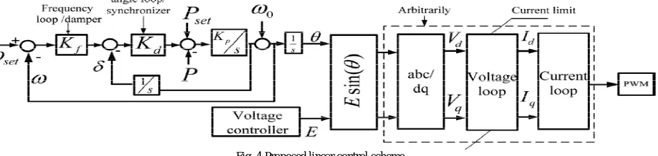
Fig. 4 Proposed linear control scheme
The above fig. 4 shows the linear power damping controller. Although the linear controller offers stable and smooth operation in many cases, it cannot ensure system stability in weak grids, where sudden large disturbances rapidly drift system dynamics to the nonlinear region which is rectified by the following non-linear controller.
Nonlinear Controller:
To overcome the above mentioned difficulty, a supplementary nonlinear controller is developed to assist the linear controller and enhance system performance under large-signal nonlinear disturbances, such as self-synchronization, disturbances in grid frequency and angle, high power injection in very weak grids and fault-ride-through conditions in such situations here come non-linear power damping controller which assists linear controller. The following fig. 5 shows the non-linear power damping controller.
Fig.5. Non-linear power damping controller
Here we will analyze the small-signal stability of a grid-connected VSC is explained. In order to assess the system dynamic behaviour in a powerless grid. The three-phase power system mainly contains a converter and its controller, RL filter, transmission line and infinite grid. Considering VSC as ideal, the controller order is evenly balanced by the VSC local load voltage. Therefore, it is capable of modeling the VSC and PWM block by an average voltage approach. The parameters of the system are presented in Table 1. The obtained model of the VSC and its controller can be obtained as follows.
The load angle dynamic equation is represented as follows and frequency dynamic expression is given by equation (4) and here ∆p is given by following expressions
∆ =̇ ∆ (7) ∆ = ∆ + ∆ (8) The voltage loop dynamic expression is given by
∆ ̇ =− ∆ + ∆ − ∆ (9) ∆ ̇ =− ∆ (10) Where is the output of the integrator, and is the filter voltage amplitude expressed by
∆ = ∆ ∆ (11)
∆ = ∆ + ∆ − ∆ (12)
∆ = ∆ + ∆ − ∆ (13) The current dynamics in the dq reference-frame are given by
∆
= (− ∆ +∆ − ∆ + ∆ ) (14)
∆
= ( ∆ +∆ − ∆ + ∆ )
(15)
At the time of design process, even though small values of Kf and larger magnitudes of yields a high stability margin and quick response, the steady-state error is abnormally incremented particularly in weak grids with high load angle. Therefore, a load angle oscillation becomes more at the point of instability during contingencies.
The entire system model is, here u is the control input.
̇ = ̇ (16) ̇ = + + (17) ̇ = + + (18)
Where = - , = - & =- and [ ] = [∆ , ∆ , ΔP]. Is described by = (u sin )/X, The parameters of the system are presented in Table 1.
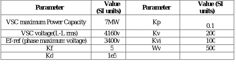
Parameter Value
(SI units) Parameter
Value (SI units)
VSC maximum Power Capacity 7MW Kp
0.1 VSC voltage(L-L rms) 4160v Kv 200 Ef-ref (phase maximum voltage) 3400v Kvi 100
Kf 5 Wv 500
Kd 1e5
Table 1: Controller Parameters
A nonlinear back-stepping power damping controller is designed and added to the linear controller to overcome the problem of weak performance and instability. The structures of the controllers are decoupled because the nonlinear controller is additional one which supplies an added signal for the linear controller.
IV.EXPERIMENTALRESULTS
The system consists of a 7.0MW VSC, filter, local load, transformer and a bridge line connecting the VSC to the grid. Having a specific value to indicate that the impedance 0.2+j0.5Ω is the equivalent impedance of the strong source
referring to the spreading (distribution) level. The simulation of the system is carried out in MATLAB/SIMULINK platform. The parameters of the controller are represented in the table 1. The local load at the output terminal is provided by the DG unit and it is joined to a strong grid by means of a very lacking strength interface with total
impedance of |Z|=|R+jX|=|4.4+j43.5|=43.7Ω. during this period , the connecting line is very nearly inductive, the power capacity of the interface line is proximate by
≈ (19)
While notations are explained here X is total reactance of the transformer, line and strong grid. Therefore, the maximum real power transfer capacity of the joining the line is equal to
Pmax=13880 /43.5≈4.44MW
This is in contrast with conventional vector control which can only exchange 0.6 p.u. real power with a grid; otherwise it might face instability. The following results depict us proposed controller under different fault conditions.
Lower Power Injection
A distance range of operating points is to be studied to determine the behaviour of the controller. It is to be imagined that, at the starting system supplies 80 KW, and t=1s, the reference power is incremented to 2.0MW.
Fig. 6 Controller performance in low-power injection
The response of real power is shown in fig.6, which views a seamless transition. The rise time is about 0.6 s and perfect reference record without any overshoot.
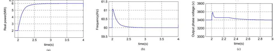
High Power Injection
The reference power is changed to 2.0MW to 6.0MW indicating closeness to the VSCs maximum power capacity at fixed voltage working and a load angle more than 1.03 rad is expected.
Fig. 7 Controller performance in high-power injection (a) Real power.(b) Frequency (c) Phase-voltage amplitude
Fig 7 (a) depicts the real power (b) frequency (c) output phase voltage variation waveforms as shown. It is to be noted that the response is smooth but contains a greater rise-time. The output phase voltage amplitude presents the controller performance to encourage VSCs voltage at the time of load angle variation to provide high real power injection. The general characteristics of the system which gives rise to voltage sag subsequent to increase in output power and at the same time with high voltage drop, which is a contrast.
Transition to island mode
The postulated sequence that may exist in DG applications to supply local critical loads is islanded operation. At t=4s the VSC is jumped to the separated mode because of fault in the grid. Reconfiguration of the system is not needed.
(a) (b)
Fig. 8 (a) and (b) shows the smooth transition without any unstable factors. Large steady state deviations in the grid connected mode are attained when Kf is decremented to obtain quick response. The respective current waveforms are observed which is smooth and fast transition because of the majority of the controller in either modes of operation.
Self-Synchronized Grid Restoration
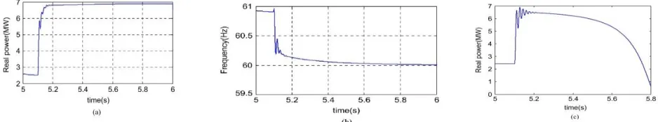
Powerless grids have more transients during resynchronization because of the fact that load angle is essentially large and after grid restoration moves to the nonlinear region freely.
Fig. 9 System performance during grid restoration (a) Real power with nonlinear supplementary controller (b) Frequency (c) Real power without the supplementary controller
Fig 9 (a) shows the respective waveforms and depicts that the system with nonlinear controller supplies smooth and quick grid connection. The system response without using the supplementary controller is depicted in fig. 9 (b) shows that powerless grid connections cause instability. Fig. 9 (c) shows the current waveform of the system with supplementary controller depicts the well-damped characteristics even in the out-of-phase reclosing modes.
Fault-Ride Through Capability: (Disturbance in the Grid Angle)
Along with the large connecting impedance, powerless grids may be affected by the sudden changes in the voltage angle and frequency.
(a) (b) (c)
Fig. 10. System performance during disturbance grid angle (a) Current waveforms subsequent to self-synchronization with supplementary Control (b) Load angle variation (c) subsequent output voltage disturbance in the grid angle
Fig. 10 shows the resulting waveforms of the load angle and phase voltage amplitude respectively, verifies that VSC easily identifies the angle variations even under high disturbances without loss of stability and reduced performance. This is a very interesting quality of the controller where it works as a virtual PLL, and automatically monitors grid frequency and angle deviations. If we observe the waveforms in Fig. 10 (b), (c) We can justify that the output voltage amplitude is drastically decremented to keep the output power limited. The fact behind that is decrement in the grid voltage angle exhibits sudden increase in output power. Therefore, the output voltage must be decreased to maintain real power stability.
Fault-Ride Through Capability: (Three Phase Fault)
Fig. 11. System waveforms subsequent to a three-phase fault (a) Real power (b) Instantaneous current waveforms (c) Amplitude of the phase voltage
Fig.11 views the waveforms of the (a) output real power, (b) current and (c) phase voltage amplitude. From the waveforms, it is known that VSC is not subjected to over-currents during three-phase faults. At the event of fault, the real power waveform is seamless and restricted, the voltage drops and the reactive power is incremented. At t = 9s, the circuit breakers on both sides of the connecting line 2 becomes active and the line is separated from rest of the grid. Large signal changes occur in the system during the isolation of the connecting line.
After the separation of the line 2 at t = 9s, voltage, real power and current replaces back to the initial conditions before the fault but the operating points are different. This verifies the uncertainties of the system during the sudden large transients. The reconnection of the connecting line 2 is smooth and the waveforms present well-damped characteristics which can be observed.
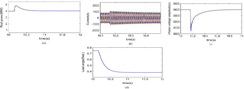
Fig. 12. System waveforms subsequent to reconnection of line 2 (a) Real power (b) Instantaneous current (c) Amplitude of the output phase-voltage (d) Load angle
If it is assumed that if the fault is cleared at t = 10.16s when line 2 is again switched into the circuit. The waveform corresponding to the reconnection of line 2 are as shown in Fig.12 (a) real power, (b) current, (c) amplitude of the phase voltage and (d) load angle. When the line 2 is activated after the re-closure, the overall system settles down in 0.7s. The reconnection of connecting line 2 is smooth and all the waveforms present well-damped characteristics.
V. CONCLUSION
eliminates PLL. A wide range of scenario has been applied to verify the effectiveness of the proposed linear controller. System performance under low-high references, transition to islanding, self-synchronization is studied.These cases are considered as large-signal disturbances, thus the proposed nonlinear controller can enhance system performance in these cases. Moreover, the controller is able to work in very weak grids with SCR less than 2 and supplies the rated power because of its damping and synchronizing power characteristics. The design process for the linear and nonlinear scenarios has been presented and simulation results were presented to validate the controller effectiveness.
REFERENCES
[1] A. Guerrero et al., “Distributed generation,” IEEE Ind. Electron. Mag, pp. 52–64, Mar. 2010.
[2] N. Flourentzou, V. G. Agelidis, and G. D. Demetriades, “VSC-based HVDC power transmission systems: An overview,” IEEE Trans. Power Electron., vol. 24, no. 3, pp. 592–602, Mar. 2009.
[3] B. Parkhideh and S. Bhattacharya, “Vector-controlled voltage-source converter- based transmission under grid disturbances,” IEEE Trans. Power Electron. vol. 28, no. 2, pp. 661–672, 2012.
[4] Y.-P. Ding and J.-H. Liu, “Study on vector control used in VSC-HVDC,” in Proc. IEEE Power Engineering and Automation Conf. (PEAM),2011.
[5] T. Noguchi, H. Tomiki, S.Kondo, and I. Takahashi, “Direct power control of PWM converter without power-source voltage sensors,” IEEE Trans. Ind. Applicant. vol. 34, no. 3, pp. 473–479, May/Jun. 1998.
[6] J. Verveckken, F. Silva, D. Barros, and J. Driesen, “Direct power control of series converter of unified power-flow controller with three-level neutral point clamped converter,” IEEE Trans. Power Del., vol. 27, no. 4, pp. 1772–1782, Oct. 2012.
[7] F. Blaabjerg,R. Teodorescu,M.Liserre, and A. V. Timbus, “Overview of control and grid synchronization for distributed power generation systems,” IEEE Trans. Ind. Electron., vol. 53, no. 5, pp. 1398–1408, Oct. 2006.
[8] L. Zhang, L. Harnefors, and H. -P. Nee, “Power-synchronization control of grid-connected voltage-source converters,” IEEE Trans. Power Syst., vol. 25, no. 2, pp. 809–819, May 2010.
[9] Q. -C. Zhong, P. -L. Nguyen, Z. Ma, and W. Sheng, “Self-synchronized Synchronverter: inverters without a dedicated synchronization unit,” IEEE Trans. Power Electron., vol. 29, no. 2, pp. 617–630, 2014.
[10] L. Zhang, L. Harnefors, and H.-P. Nee, “Modeling and control of VSCHVDC links connected to island systems,” IEEE Trans. Power Syst., vol. 26, no. 2, pp. 783–793, May 2011.