Discrete Fourier Transform Design Using
Floating Point Numbers
Shilpa Rathod 1, Dr. Srividya P 2
P.G. Student, Department of Electronic and Communication Engineering, S.J.B Institute of Technology,
Bengaluru, India1
Associate Professor, Department of Electronic and Communication Engineering, S.J.B Institute of Technology
Bengaluru, India1
ABSTRACT: Generally most of the modern microprocessor use floating point IEEE754 format in large number of applications. In this paper Floating point arithmetic design and DIT FFT design is proposed. The floating point operation is considered are addition, subtraction and multiplication unit. Design is done in Verilog , Simulation is carried out in Xilinx ISE Design Suite 14.3.
KEYWORDS: IEEE754 Format; add/sub; Floating point; Algorithm; DIT FFT
I. INTRODUCTION
Most of the arithmetic operations play a vital role for designing of the application specific method and also designing in digital processor. Due to the advancements in the VLSI circuits lots of composite circuits are effortlessly implemented and designed nowadays .This is due to the fact that enormous increase in the chip integration technology, most of chips are designed in very small size and with high range of accuracy and speed. In order to be free from scaling, overflow, underflow errors which occur in the fixed point number and to overcome this type errors floating point representation are preferred because of the presence of high dynamic range. Algorithms are been used for the designing of large number circuits which actually seemed very tough in earlier days and now various investigation are done for designing of an unconventional circuits along with the conventional type of design circuits. As we know that real numbers are very easy for hand computations and it is convenient way to use, but it has an added disadvantage that it is not suitable for general purpose calculations .For any type of scientific computations to carry out it should satisfy some of the criteria such that the size of a number should be small for the storage purpose and the operations must be easy portability should be high and results should be accurate. For analysis and implementation of discrete signals the algorithm that widely used is DFT .Conversion such as time domain to frequency domain and from frequency to time domain can be carried out .for optimized result FFT algorithm such as butterfly based architecture is used depending upon the no. of samples ‘N’.
This paper presents the designing of an arithmetic unit using floating point numbers and designing of a DIT FFT design using various Multiplication and addition algorithms.
II.RELATED WORK
A. Fixed Point Numbers representation
Representation of fraction part using fixed number of bits makes fixed point number simple and easy to use because of the precision. This mean that number of bits used to represent the fractional part is precise to the fixed point number. In fixed point number representation ,precision is inversely proportional to the dynamic range which mean increase in the precision results in decrease in the dynamic range[1] .Therefore fixed point number representation technique are not widely used due the less dynamic range and large number of computation. This makes representation of fractional part becomes very difficult.
B. Floating Point Numbers representation
Floating point numbers are those numbers where there is a fixed number of digit before and after decimal point. For representing floating point number decimal point plays a major role. Depending upon the decimal point floating point bits are considered. The major disadvantages using with floating point number is it lacks accuracy and lowers the process speed. Fractional part representation is carried out using floating point number. Most of the languages are supported by the processors and large number of data computations is carried out. Hence for every computation to be carried out operating system should support the IEEE Standards.
Representation of a Floating Point numbers is shown as follows:
Sign bit
Exponent bit
Significant bit
Figure1. IEEE754 Format
As shown in Figure 1, Floating pint number which is of 32 bit is divided into three parts namely Sign bit , Exponent and an Significant bit. Hence it is termed to be IEEE754 Format.
Large dynamic range is of key importance to a floating point unit. Precision is factor of floating point unit. Normally the floating-point number has mainly three subparts: mantissa (M) ,sign (S) and exponent (E). The value can be as (-1)S× base*E *M * of base which is the mainly significant aspect which is important to know in prior while going with floating point notations. Mainly it is 16 for hexadecimal numbers, 2 is for binary and 10 for the decimal.
C. Basics of IEEE754 Format
Mainly IEEE754 format is developed for representation of a floating point arithmetic unit and the specification of these standards is mainly used for most the arithmetic operations such as rounding off and exception operations.[2]
The main advantage of using IEEE754 Standards is to i. Minimize the anomalies
ii. Enhance the portability iii. Improve numeric quality
Various type of implementation are carried out using this type of format such as pipelined implementation .Further IEEE754 Format undergoes operations such as multiplication of the magnitudes, addition of exponent terms ,checking out with the sign bits, normalisation, rounding off and exception operations.
III.ALGORITHMS AND DFT IMPLEMENTATION
As in the Figure 1, floating point numbers are mainly represented using these IEEE 754 format in order to get an easy way of calculation. Here it has been divided to three different bits
A. Addition / Subtraction of floating point numbers
1. First step in addition part is by looking at the exponents, if exp1<exp2 the swapping of operands are done. Then subtraction of exp1 and exp2 >=0.
2. If signs of an operand 1 and operand 2 differ then it is complimented by 2. 3. Operands 2 in p-bit register and shifted difference in the right position.
4. Shifting operation takes place from the shifted out bits to the most significant bit.
5. Addition computation of signs are carried out by doing addition of operand 2 to p-register containing the operand 1 .
6. If the signs of the operands are similar then there will be a carry out in the above step 4. 7. Adjusting of the results are carried out.
B. Multiplication of floating point numbers
1. Conversion in scientific notation is carried out explicitly.
2. Let e1 and e2 be the exponent of the two operands and resulting is the sum of the exponents. 3. Multiplication of the mantissa term of two operands are carried out.
4. Sign bits are added in the multiplication part in order to get the final bit of sign
5. Finally the results are converted to floating point notation by truncating if it is necessary.
C. Decimation in Time DFT algorithm
Conversion of a signal from time domain to frequency domain is called Discrete Fourier Transform and the inverse from frequency domain to time domain is called as Inverse Discrete Fourier Transform. Figure 2 shows the butterfly diagram which consists of an adder and a sub tractor unit of floating point numbers. A and B are the input data which are given to the structure. Finally complex output is obtained of individual input data provided. In order to calculate the DFT divide and conquer approaches are carried out depending upon the number of successive bits with N points. Therefore decomposition operations take place. Decimation in time undergoes the computation by dividing N points in two parts. The two parts are sum upon even part and sum upon odd part. Figure 3 shows the Decimation in Time DFT with N equal to 8 point and it needs N/2 butterflies at each stage of operation. X(k) is frequency domain and x(n) is the time domain. N is the number of samples being used. In this butterfly based architecture is used and the resource sharing techniques mainly decreases the use of hardware resource requirements. Here four butterflies are used in DFT architecture and these are mainly used to calculate the time domain data and frequency domain data .
The butterfly diagram where the two input data are given and the operations such a floating point addition and floating point subtraction takes place in order to get a complex output data A and complex output data B.
Figure 3. Decimation in Time FFT (N=8)
The 8 bit DIT FFT algorithm where the 8 corresponding inputs are given in order to get an corresponding output results in complex form such that it consists both real and imaginary terms.
IV. SIMULATION RESULTS
The design is carried out using two 32 bit which has been seperated into sign , exponent and an mantissa terms.Depending on the value of sign bit the operations such as addition and subtraction is carried out.The exponent term is of 8 bit . Hence concatenation of mantissa term is done by using one gurad bit. Normalisation of mantissa is done by the use of shifters.adders of mantissa bit. Floating Point Addition,multiplication and the simulated DITFFT results have been shown.
Figure 4 shows the simulation result of a floating point addition where the two floating point input values are given and the corresponding floating point addition output results are obtained which describes sign bit , exponent bit and the fractinal bit.
Figure 5.Multiplication of Floating Point Numbers
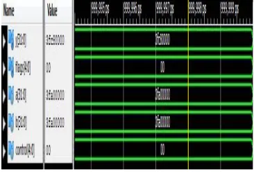
Figure 5 shows the simulation result of a floating point multiplication where the values of floating point are given as input and the floating point multiplied results are obtained such that the sign bit ,exponent bit and the fractional bits are determined.Figure 6 shows the simulation results of an DIT FFT algorithm hence the decimation from time domain to frequency domain is obtained and the input complex values are decimated and the frequency domain results are obtained.
Figure 6.DIT FFT Simulation result
V. CONCLUSION
The design was done in Xilinx ISE tool using Verilog. The simulated results of floating point adder, multiplier are shown in Figure4 and Figure 5 and the simulated results of DFT is shown in Figure 6 which is decimation in time domain. Implemented architecture produces the precise value of DFT and this can used for further implementation of DFT designs such as Pipelined architecture design and DIF FFT design. This paper shows the design of floating point addition, Multiplication and DIT FFT design.
REFERENCES
[2]. Kota Solomon Raju,Vijeta Sengar,Mridula Gangal, Pramod Tanwar and P.Bhanu Prasad, “Hardware Implementation of Discrete Fourier transform and its Inverse Using Floating Point Numbers”, International Journal of Computer Technology and Electronics Engineering(IJCTEE)Volume 2,Issue 2
[3]. J.G.Proakis and D.G. Monolakis, Digital Signal Processing, Principles, algorithms and applications, Prentice Hall India publication, page no. 459-462.
[4]. David Goldberg and Xerox Palo, Compute Arithemetic, Elsevier Science 2003, ppH13-H27.
[5]. Sang-In Cho and Kyu-Min Kang, “A Low –Complexity 128-Point Mixed-Radix FFT Processor for MB-OFDM UWB Systems” ETRI Journal,Volume 32,Number !, February 2010.
BIOGRAPHY
Shilpa Rathod M.Tech student in the specialization of VLSI Design and Embedded Systems of ECE Department , S J B Institute of Technology, Bangalore, India