ABSTRACT
IM, JEONG HYUK. Performance Evaluation of Chip Seals for High-Volume Roads Using Polymer-Modified Emulsions and Optimized Construction Procedures. (Under the direction of Dr. Y. Richard Kim.)
This dissertation presents research to develop guidelines for chip seals under
high-volume traffic. It examines the characteristics of asphalt surface treatments (ASTs) that
include their material properties (curing and adhesive behavior) as well as their laboratory
performance (aggregate retention, bleeding, rutting, skid resistance, and surface texture) and
field performance (visual observation and surface texture). The curing and adhesive behavior
of ASTs is evaluated using the evaporation test, bitumen bond strength test, and Vialit test.
Laboratory performance is investigated using the third-scale model mobile load simulator
test, Vialit test, and laser profiler. Field performance is evaluated using the laser profiler and
visual observations based on the NCDOT Pavement Condition Survey Manual.
This study also uses laboratory performance tests to evaluate the benefits of
polymer-modified emulsions in ASTs. Refined AST construction procedures are developed based on
previous research results and information gleaned from a literature review. Based on this
information, a total of 12 field test sections are constructed for three traffic volumes (5,000,
10,000, and 15,000 ADT). In order to evaluate the performance of the ASTs constructed in
the field, samples are extracted after construction and then tested in the laboratory. The field
test sections are monitored periodically (on the day of construction and before and after the
Fog seals are also evaluated in this study as a means of reducing potential aggregate
loss problems of ASTs in high traffic volume roadways. Curing behaviors of unmodified and
polymer-modified emulsions are investigated using laboratory tests. These tests include the
evaporation test and two newly developed in-situ test methods, rolling ball test and damping test.
Guidelines for chip seals under high-volume traffic are developed based on the
determined performance characteristics of ASTs in both the laboratory and the field, and the
field monitoring results. However, a few additional factors that affect chip seal construction,
e.g., the condition of old pavement, performance uniformity coefficient analysis, and
maximum allowable traffic volume, should be studied in more depth and are recommended
for future research. Also, this research develops a method to predict aggregate loss in the
field using mean profile depth (MPD) analysis, which employs the aggregate loss results and
the MPDs obtained from both the laboratory tests and the field monitoring. The results of the
predictions are similar to field performance ratings, but further research is needed to verify
Performance Evaluation of Chip Seals for High Volume Roads Using Polymer-Modified Emulsions and Optimized Construction Procedures
by Jeong Hyuk Im
A dissertation submitted to the Graduate Faculty of North Carolina State University
in partial fulfillment of the requirements for the Degree of
Doctor of Philosophy
Civil Engineering
Raleigh, North Carolina
2013
APPROVED BY:
_______________________________ _______________________________
Dr. Y. Richard Kim Dr. Akhtarhusein A. Tayebali
Chair of Advisory Committee
_______________________________ _______________________________
DEDICATION
To my family,
I would like to dedicate my dissertation work to my parents and sister.
There is no doubt in my mind that without their continued encouragement, support, and love,
I could not achieve this work.
I also wish to express special feeling of gratitude to my wife, Hyeseung Lee,
and my son, Jayden Jaegyun Im.
It is hard to say how much I love you.
You are everything to me.
The glory of God,
I wish to dedicate my dissertation work to God.
I always appreciate Mahanaim, which is a group in my church.
All Mahanaim members have given invaluable help to my family.
The LORD your God is with you, he is mighty to save.
BIOGRAPHY
Jeong Hyuk Im was born in Seoul, Korea on March 1, 1977. He received his
Bachelor’s degree and Master’s degree in Civil Engineering in 2003 and 2005 from
Kyunghee University in Korea, respectively. After graduation he worked as an engineer at
Daehan Consultants for one year and then worked as a researcher at the Korea Expressway
Corporation Research Institute (KECRI) for two years. In 2009 he then moved to North
ACKNOWLEDGEMENTS
First of all, I would like to acknowledge and thank my committee members who were
more than generous with their expertise and precious time. A special thanks to Dr. Y.
Richard Kim, my advisor for his advice, support, guidance, and most of all patience
throughout the entire graduate study. I also wish to thank Dr. Akhtarhusein A. Tayebali, Dr.
Mohammed A. Gabr, and Dr. Min Liu for serving on my committee.
I would like to acknowledge and thank PPG members. I wish to thank Dr. Cassandra
Hintz for her valuable advice and assistance on my research. I also thank Mehdi Mashayekhi
for all his help. Special thanks go to Javon Marcell Adams and Mohammad Ilias who were
strong enough to work in field construction for my research. Without their continued support
and help throughout my graduate study, I could not achieve this work.
I also wish to acknowledge Dennis Wofford and Averette Moore who are working at
the North Carolina Department of Transportation. They have given invaluable direction and
support to the field construction for this research.
Finally, I express my deep gratitude to my fellow members: Yeongtae Choi,
Hongjoon Park, Jongsub Lee, Dahae Kim, Seonghwan Cho, and all other members in Dr.
Kim’s research group. I am also thankful to Diane Gilmore for her support, kind words, and
TABLE OF CONTENTS
LIST OF TABLES….………...………..viii
LIST OF FIGURES……….….xi
1. INTRODUCTION ... 1
1.1 Research Needs and Significance ... 1
1.2 Research Objectives ... 3
1.3 Dissertation Organization ... 3
2. LITERATURE REVIEW ... 5
2.1 General ... 5
2.2 Distresses in ASTs ... 6
2.3 Emulsion Properties ... 6
2.4 Polymer-Modified Emulsion ... 8
2.4.1 Modified Emulsion Properties ... 8
2.4.2 Modified Emulsion Types ... 10
2.4.3 Polymer-Modified Emulsion Performance ... 11
2.4.4 Curing and Adhesive Behavior of Polymer-Modified Emulsions ... 15
2.5 Construction Procedures Used for Modified Chip Seals at High Traffic Volumes .... 16
2.6 The Use of Modified Chip Seals for Increased Traffic Volume Roads ... 23
2.6.1 Modified Chip Seals for Higher Traffic Volume Roads ... 23
2.6.2 Fog Seal Application ... 25
3. TEST PROCEDURES AND ANALYSIS CONCEPTS ... 36
3.1 Materials ... 36
3.1.1 Aggregate ... 36
3.1.2 Aggregate Performance Uniformity Coefficient (PUC)... 37
3.1.3 Emulsion Type ... 38
3.1.4 Type of Chip Seal ... 40
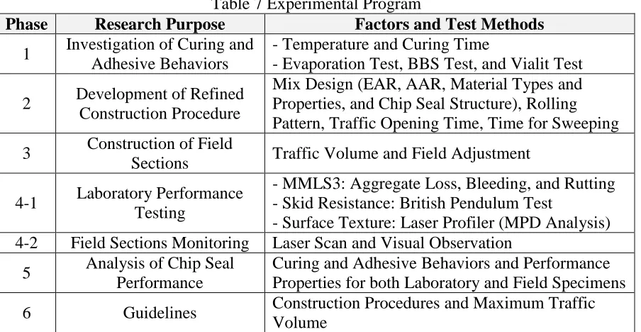
3.2 Experimental Program ... 41
3.3.1 Sample Fabrication Facility ... 44
3.4 Experimental Test Methods ... 46
3.4.1 Evaporation Test ... 47
3.4.2 BBS Test (PATTI Test) ... 48
3.4.3 Ignition Oven Test ... 53
3.4.4 Flip-Over Test ... 54
3.4.5 Vialit Test ... 54
3.4.6 Third Scale Model Mobile Load Simulator (MMLS3) Performance Test ... 55
3.4.7 Surface Texture Evaluation ... 61
3.4.8 Fog Seal Field Test Evaluation ... 67
4. LABORATORY EVALUATION OF AST PERFORMANCE ... 72
4.1 Chip Seal Performance ... 72
4.1.1 Curing Time Study ... 72
4.1.2 Chip Seal Performance Test ... 86
4.2 Fog Seal Performance ... 95
4.2.1 Fog Seal Curing Time Study ... 95
4.2.2 Fog Seal Field Test ... 110
4.2.3 Fog Seal Performance Test ... 117
5. FIELD EVALUATION OF AST PERFORMANCE ... 127
5.1 Development of Refined Construction Procedure ... 127
5.2 Construction of Field Section Using Different Construction Procedures ... 133
5.2.1 Field Construction Timeline ... 133
5.2.2 Field Sampling and Testing ... 134
5.2.3 Construction Target Rates ... 136
5.5 Field Section Monitoring ... 148
5.5.1 Pavement Distress Conditions for Pavement Condition Survey ... 148
5.5.2 Visual Observation ... 154
5.5.3 MPD Comparison ... 167
5.5.4 Prediction of Aggregate Loss in Field Sections ... 169
6. RECOMMENDED GUIDELINES FOR CHIP SEALS UNDER HIGH-VOLUME TRAFFIC ... 173
6.1 Pavement Condition ... 173
6.2 Materials ... 174
6.2.1 Aggregate ... 174
6.2.2 Emulsion ... 180
6.3 Weather Conditions ... 186
6.4 Seal Types ... 186
6.5 Construction Procedures ... 189
6.6 Traffic Volume ... 191
7. CONCLUSIONS AND RECOMMENDATIONS FOR FURTHER RESEARCH ... 194
7.1 Conclusions ... 194
7.1.1 Evaluation of Chip Seal Performance ... 194
7.1.2 Evaluation of Fog Seal Performance ... 197
7.1.3 Evaluation of Field Tests ... 199
7.1.4 Recommended Guideline ... 201
7.2 Recommendations for Further Research ... 203
7.2.1 Prediction of Aggregate Loss in the Field ... 203
7.2.2 Guidelines for Chip Seals ... 203
7.2.3 Life Cycle Cost Analysis ... 204
LIST OF TABLES
Table 1 Best Practices for Constructing High Volume Chip Seals (Gransberg and James 2005)
... 17
Table 2 Comparison of Chip Seal Construction Factors ... 23
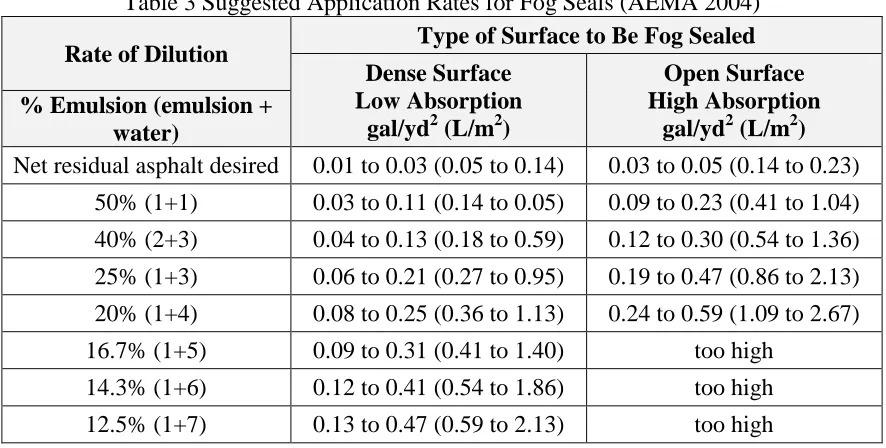
Table 3 Suggested Application Rates for Fog Seals (AEMA 2004) ... 28
Table 4 Pros and Cons of Fog Seal Application ... 30
Table 5 AEMA Recommendations for Application Rates ... 31
Table 6 Summary of Guidelines Used for Fog Seals ... 33
Table 7 Experimental Program ... 41
Table 8 Test Methods for Performance Properties ... 47
Table 9 Comparison of BBS Procedure and Modified BBS Procedure ... 52
Table 10 Correction Factors for Each Aggregate Type ... 53
Table 11 Potential BBS Limit Obtained from Linear Model Using the Correlation between BBS and Aggregate Loss for Granite Aggregate ... 85
Table 12 Potential BBS Limit Obtained from Linear Model Using the Correlation between BBS and Aggregate Loss for Lightweight Aggregate ... 85
Table 13 Results of Statistical Analysis for Emulsion Types: Aggregate Retention Performance of Laboratory Samples ... 87
Table 14 Results of Statistical Analysis for Emulsion Types: Bleeding Performance of Laboratory Samples ... 91
Table 15 Results of Statistical Analysis for Emulsion Types: Rutting Performance of Laboratory Samples ... 95
Table 16 Material Properties of Study Emulsions ... 96
Table 21 Rolling Ball Test for CSS-1h, ReviveTM, and Grip-Tight Emulsions with 0.06 and
0.12 gal/yd2 (0.27 and 0.54 L/m2) at 25°C and 30°C ... 112
Table 22 Percentage of Stained Pixels for Damping Test for All Study Emulsions at 30°C 114 Table 23 Percentage of Stained Pixels for Grip-Tight Emulsion at 25°C and 30°C ... 115
Table 24 Aggregate Loss from the Vialit Tests Using CSS-1h and CQS-1h Emulsions ... 118
Table 25 MPD Values ... 121
Table 26 Skid Number from BPT ... 126
Table 27 Field Construction Variables ... 128
Table 28 Field Section Information ... 132
Table 29 Construction Target Application Rates ... 137
Table 30 Field Construction Conditions ... 141
Table 31 Results of Statistical Analysis for Emulsion Types: Aggregate Retention Performance of Field Samples ... 142
Table 32 Results of Statistical Analysis for Emulsion Types: Bleeding Performance of Field Samples ... 144
Table 33 Results of Statistical Analysis for Emulsion Types: Rutting Performance of Field Samples ... 148
Table 34 Alligator Cracking Failure Level (NCDOT Pavement Condition Survey Manual) ... 149
Table 35 Transverse Cracking Failure Level (NCDOT Pavement Condition Survey Manual) ... 150
Table 36 Rutting Failure Level (NCDOT Pavement Condition Survey Manual) ... 151
Table 37 Raveling Failure Level (NCDOT Pavement Condition Survey Manual) ... 152
Table 38 Bleeding Failure Level (NCDOT Pavement Condition Survey Manual) ... 152
Table 39 Ride Quality Failure Level (NCDOT Pavement Condition Survey Manual) ... 153
Table 40 Summary of Field Observation ... 166
Table 41 Reduction in MPD from Field Sections ... 170
Table 42 Pavement Condition ... 174
Table 44 Emulsion Cost Information (NCDOT 2013) ... 180
Table 45 Application Rates Information ... 181
Table 46 Minimum Temperature Information ... 186
Table 47 Construction Cost Information (NCDOT 2012) ... 187
Table 48 Recommendation of Seal Type ... 189
LIST OF FIGURES
Figure 1 Schematic diagram of fully cured unmodified asphalt and SBR latex
polymer-modified asphalt (Takamura 2003) ... 9
Figure 2 Rolling patterns ... 19
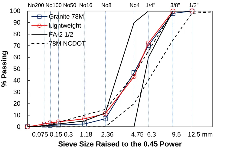
Figure 3 Aggregate particle size gradation in Minnesota: FA-2, FA-2 1/2, and FA-3 ... 21
Figure 4 Emulsion curing procedure ... 35
Figure 5 Aggregate particle size gradations ... 36
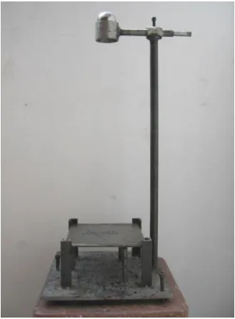
Figure 6 Greenhouse for temperature control ... 44
Figure 7 Emulsion spraying procedure ... 45
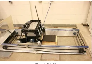
Figure 8 ChipSS ... 46
Figure 9 Evaporation test samples in environmental chamber ... 48
Figure 10 PATTI test; (a) PATTI device and (b) schematic of piston assembly (PATTI Manual) ... 49
Figure 11 PATTI samples in environmental chamber for: (a) emulsion and (b) fog seal emulsion ... 49
Figure 12 Molds: (a) dimensions (mm) and (b) attached molds to aggregate substrate ... 50
Figure 13 Dimensions (mm) of pull-stub: (a) profile view and (b) bottom view (AASHTO-TP 91) ... 51
Figure 14 Failure types: (a) cohesive failure and (b) adhesive failure. ... 51
Figure 15 Vialit test apparatus ... 54
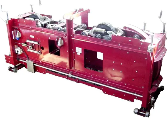
Figure 16 MMLS3 ... 56
Figure 17 MMLS3 test specimens before loading ... 56
Figure 18 Example of bleeding analysis (SBS CRS-2P with granite 78M aggregate): (a) sample after bleeding test, (b) sample applied bleeding area, and (c) bleeding area ... 58
Figure 19 Schematic diagram of a typical cross-section of triple seal ... 60
Figure 20 Triple seal specimen after rutting test ... 61
Figure 22 Schematic diagram of MPD determination (Transit New Zealand 2005) ... 64
Figure 23 Equipment for the: (a) LWST and (b) BPT ... 65
Figure 24 Correlation between average BPN and average SN ... 66
Figure 25 Rolling ball test: (a) side view and (b) plane view ... 68
Figure 26 Damping test: (a) applied dead weight and (b) after testing ... 70
Figure 27 Examples of stained pads for damping test at 30°C: (a) 100%, (b) 44.1%, (c) 10.5%, (d) 6.5%, (e) 3.5%, (f) 2.4%, (g) 1.5%, and (h) 0.1% ... 71
Figure 28 Curing comparison of CRS-2, CRS-2L, HP CRS-2P, and SBS CRS-2P emulsions ... 73
Figure 29 Bond strength versus curing time for granite aggregate types at: (a) 15C, (b) 25C, and (c) 35C ... 75
Figure 30 Bond strength versus curing time for lightweight aggregate types at: (a) 15C, (b) 25C, and (c) 35C ... 76
Figure 31 Digital images of lightweight aggregate surface: (a) color, (b) grayscale, and (c) DIP analysis ... 78
Figure 32 Adhesive behavior at different curing times and at (a) at 35C, (b) 25C, and (c) 15C ... 80
Figure 33 Adhesive behavior at different curing temperatures for: (a) CRS-2, (b) CRS-2L, (c) HP CRS-2P, and (d) SBS CRS-2P ... 81
Figure 34 Correlation between bond strength and aggregate loss from Vialit test for granite aggregate at: (a) 35C, (b) 25C, and (c) 15C ... 83
Figure 35 Correlation between bond strength and aggregate loss from Vialit test for lightweight aggregate at: (a) 35C, (b) 25C, and (c) 15C ... 84
Figure 41 Evaporation test results for CSS-1h and CQS-1h emulsions of 0.06, 0.12, 0.19, and
0.26 gal/yd2 (0.27, 0.54, 0.86, and 1.18 L/m2) at: (a) 20°C, (b) 30°C, and (c) 40°C ... 98
Figure 42 Evaporation test results at all temperatures for 0.06, 0.12, and 0.19 gal/yd2 (0.27, 0.54, and 0.86 L/m2) of: (a) CSS-1h, (b) ReviveTM, and (c) Grip-Tight emulsions 99 Figure 43 Evaporation test results for CSS-1h, ReviveTM, and Grip-Tight emulsions of 0.06,
0.12, and 0.19 gal/yd2 (0.27, 0.54, and 0.86 L/m2) at: (a) 20°C, (b) 30°C, and (c)
40°C ... 100
Figure 44 Evaporation test results for CSS-1h, ReviveTM, and Grip-Tight emulsions of 0.12 gal/yd2 (0.54 L/m2) at: (a) 20°C, (b) 30°C, and (c) 40°C ... 101 Figure 45 Evaporation test results for CSS-1h, ReviveTM, and Grip-Tight emulsions with
same asphalt residue ... 104
Figure 46 Evaporation test results with 0.12 gal/yd2 (0.54 L/m2) of CSS-1h, ReviveTM, and Grip-Tight emulsions for comparison same asphalt residue and recommended
dilution rate ... 104
Figure 47 BBS test results at all EARs and emulsions at: (a) 25°C, (b) 30°C, and (c) 35°C 107
Figure 48 Rolling ball test for CSS-1h, ReviveTM, and Grip-Tight emulsions with 0.06 and 0.12 gal/yd2 (0.27 and 0.54 L/m2) at: (a) 25°C and (b) 30°C ... 111 Figure 49 Comparison between BBS test and field tests at 30°C: (a) damping test, (b) rolling
ball test for CSS-1h, (c) rolling ball test for Revive, and (d) rolling ball test for
Grip-Tight ... 117
Figure 50 Aggregate loss performance of fog seal specimens: (a) aggregate loss and (b)
cumulative aggregate loss ... 119
Figure 51 Bleeding test results for CSS-1h, ReviveTM, and Grip-Tight emulsions ... 120 Figure 52 MPD vs. No. of wheel passes for: (a) CSS-1h, (b) ReviveTM, and (c) Grip-Tight 122 Figure 53 MPD vs. No. of wheel passes for: (a) 0.08 (0.36), (b) 0.12 (0.54), and (c) 0.16
(0.72) gal/yd2 (L/m2) of EARs ... 123 Figure 54 Skid number vs. No. of wheel passes for: (a) CSS-1h, (b) ReviveTM, and (c)
Figure 55 Field construction sites: (a) Chin Page Road (low volume), (b) Farrington Road
(medium volume), and (c) Carver Street (high volume) ... 130
Figure 56 Test section diagram: (a) chip seal section and (b) chip seal with fog seal section
... 131
Figure 57 Field construction timeline ... 134
Figure 58 Field sampling: (a) Vialit sample template, (b) Vialit samples, (c) MMLS3 sample
template, and (d) MMLS3 samples ... 135
Figure 59 Laser scanning in the field ... 135
Figure 60 Ignition oven test sample: (a) before test and (b) after test ... 137
Figure 61 Actual application rates for triple-seal sections: (a) AARs, (b) EARs, and (c)
application ratios (AAR/EAR) ... 139
Figure 62 Actual application rates for double-seal sections: (a) AARs, (b) EARs, and (c)
application ratios (AAR/EAR) ... 140
Figure 63 MMLS3 aggregate loss results for field samples ... 143
Figure 64 Bleeding analysis for field samples ... 145
Figure 65 Transversal profiles for field samples: (a) CRS-2, (b) CRS-2L, (c) HP CRS-2P,
and (d) SBS CRS-2P emulsions ... 146
Figure 66 Rut depth growth (semi-log scale) ... 147
Figure 67 Alligator cracking failure level (NCDOT pavement condition survey manual) .. 150
Figure 68 Transverse cracking failure level (NCDOT pavement condition survey manual) 151
Figure 69 Raveling failure level (NCDOT pavement condition survey manual) ... 152
Figure 70 Bleeding failure level (NCDOT pavement condition survey manual) ... 153
Figure 71 Section 1 (CRS-2 with fog seal): (a) different color appearance between CSS-1h
and Revive emulsions, (b) CSS-1h surface texture, and (c) Revive surface texture
Figure 73 Section 3 (CRS-2L): (a) triple seal surface texture and (b) alligator cracks on single
seal ... 158
Figure 74 Section 4 (SBS CRS-2P): (a) triple seal surface texture and (b) single seal preventing cracks ... 159
Figure 75 Section 5 (FiberMat Type A): double seal surface texture ... 159
Figure 76 Section 6 (CRS-2L triple seal with fog seals): (a) CSS-1h and (b) Revive ... 161
Figure 77 Section 7 (CRS-2L): triple seal surface texture ... 162
Figure 78 Section 8 (SBS CRS-2P): triple seal surface texture ... 162
Figure 79 Section 9 (FiberMat Type A): double seal surface texture ... 163
Figure 80 Section 10 (CRS-2L triple seal) ... 164
Figure 81 Section 11 (SBS CRS-2P triple seal) ... 164
Figure 82 Section 12 (FiberMat Type A double seal) ... 165
Figure 83 Field performance rating ... 167
Figure 84 MPD values: (a) single seals on low traffic volume, (b) low traffic volume, (c) medium traffic volume, and (d) high traffic volume sections ... 168
Figure 85 Correlations between aggregate loss and reduction in MPD by MMLS3 test ... 170
Figure 86 Predicted aggregate loss in field sections ... 171
Figure 87 Effect of PUC in performance tests for granite 78M aggregate: (a) aggregate loss and (b) bleeding ... 176
Figure 88 Effect of PUC in performance tests for lightweight aggregate: (a) aggregate loss and (b) bleeding ... 178
Figure 89 Comparison of performance tests between single seals and multiple seals ... 179
Figure 90 MMLS3 aggregate retention comparison of different conditions: (a) single seal with granite 78M aggregate, (b) single seal with lightweight aggregate, and (c) multiple seals ... 182
Figure 91 Vialit aggregate retention comparison of different conditions: single seal with (a) granite 78M aggregate and (b) lightweight aggregate ... 183
Figure 93 Rutting resistance comparison of different conditions ... 184
Figure 94 Field performance rating comparison of different conditions ... 185
Figure 95 Performance comparisons of different seal types: (a) aggregate retention by
MMLS3 test, (b) bleeding by MMLS3 test, and (c) field performance ratings ... 188
Figure 96 Construction procedure timeline ... 190
Figure 97 MPD analysis: relationships between (a) MPD and traffic volumes in field, (b)
1.
INTRODUCTION
1.1
Research Needs and Significance
As the general performance of roadways in the United States has deteriorated over
time, an increased interest in preventive maintenance and rehabilitation has come to the fore.
Without appropriate preventive maintenance over the course of a pavement’s life cycle, the
cost to restore the pavement more than quadruples. Chip seals are among the most efficient
and cost-effective methods utilized by state highway agencies to preserve and rejuvenate
existing pavements. For example, in North Carolina, although approximately 8% of roadway
pavement expenditures are spent on surface treatment construction, that percentage
constitutes about 50% of the miles paved. Thus, it becomes imperative for agencies to
optimize the use of these treatments in terms of prolonged service life, decreased life cycle
costs, increased operational efficiency, and enhanced safety.
A series of researches funded by the NCDOT has shown various ways to improve
chip seal performance. These improvements include the use of: (1) lightweight aggregate
with uniform gradation, (2) polymer-modified emulsions (PMEs), and (3) optimized rolling
protocols. Specifically, the findings from the HWY-2007-06 research, Performance-Based
Analysis of Polymer-Modified Emulsions in Bituminous Surface Treatments, clearly indicate
a significant improvement in the performance of chip seals constructed with PMEs, and that
the curing behavior of these modified chip seals is quite different from that of unmodified
chip seals.
With the increased levels of effectiveness that PMEs provide, as compared to their
unmodified counterparts, the use of chip seals on high-volume roads is now feasible and
provides some of the same benefits that chip seals have been shown to provide for
low-volume roads. NCDOT Road Maintenance Supervisors have already begun constructing chip
increasingly important as traffic levels steadily increase and state budgets decrease. The
economic benefits of using chip seals on high-volume roads is that they extend the life of the
pavement and thus maximize the funds that were initially invested into the road construction.
This extension of the pavement life in turn delays the time by which major rehabilitation or
complete reconstruction would be necessary, thus stretching state tax dollars further on
high-volume roads where major rehabilitation and reconstruction are very costly.
Moreover, the HWY-2006-06 research shows that changes in rolling patterns can
greatly improve aggregate retention performance. However, the emulsion used in that
research was CRS-2 emulsion, not PME. The very different curing and adhesive behavior of
PME demands that the construction procedure must be optimized for the modified chip seals
in order to maximize the benefits of polymer modification. The respective findings from
these two researches strongly suggest that by using PMEs and by optimizing the construction
procedures for modified chip seals, chip seals can indeed be used for roads that have a higher
traffic volume than unmodified chip seals can handle.
One of the primary concerns regarding the use of chip seals in high-volume roads is
the presence of loose stone. A fog seal, which is an emulsified product placed on top of a
chip seal, is designed to mitigate this problem by ‘locking down’ the top layer of stone. The
Asphalt Emulsion Manufacturers Association (AEMA) defines a fog seal as “a light spray
application of diluted asphalt emulsion used primarily to seal an existing asphalt surface to
reduce raveling and enrich dry and weathered surfaces” (AEMA 2004). Other states have
employed fog seals in their respective chip seal operations and, most recently, the Federal
Highway Administration (FHWA) and the Foundation for Pavement Preservation have
co-sponsored a research that evaluates the sprayed application of polymer surface seals. The
research results show that such sealants add new asphalt to seal the surface, and rejuvenators
disadvantages include the delay in opening to traffic and reduction in skid resistance (Jahren
et al. 2007).
At this time, the NCDOT rarely uses fog seals in conjunction with its chip seal
operations. Recognizing the significant proportion of chip seal pavements in the NC highway
network and that the main problem with the chip seal is loose stone, it is deemed important to
investigate the potential of fog seals as a cost-effective method to improve the performance
of chip seals. This dissertation herein describes a research effort based on field and
laboratory experimental program to develop guidelines regarding the maximum amount of
traffic that modified chip seals can support using improved construction procedures and fog
seals.
1.2
Research Objectives
The primary objectives of the research are:
to optimize construction procedures for polymer-modified chip seals;
to determine optimal fog seal application rates for chip seals commonly used in
North Carolina;
to compare the aggregate loss and skid resistance of chip seals with and without fog
seals; and
to develop guidelines for the amount of heavy traffic that the modified chip seals
can support.
1.3
Dissertation Organization
This dissertation is composed of eight chapters. Chapter 1 describes the research
needs and objectives. The literature review of modified chip seal and fog seal applications
are summarized in Chapter 2. In Chapter 3, experimental test program, test procedures, and
analysis concepts are described. Chapter 4 describes the laboratory evaluation of the asphalt
surface treatments (ASTs) performance. Chapter 5 provides the field evaluation of ASTs
chip seals under high traffic volume. Chapter 7 offers conclusions and recommendations for
2.
LITERATURE REVIEW
2.1
General
For the asphalt surface treatments (ASTs), there are several terms, such as chip seal,
seal coat, surface treatment, bituminous surface treatment, spray seal (Austria), and surface
dressing (United Kingdom). In the North Carolina Department of Transportation (NCDOT)
specification, the term of ASTs is used officially.
The chip seal offers significant advantages, primarily as an economical and efficient
means to provide skid resistance and fast construction. Generally, the cationic rapid setting
(CRS) type of emulsion is the most commonly used asphalt for chip seals on low-volume
roads. Chip seals have proved to be cost effective due to their low initial costs in comparison
with thin asphalt overlays and due to other factors that affect treatment selection decisions
where the structural capacity of the existing pavement is sufficient to sustain its existing
loads (Gransberg 2006).
Due to the low-cost maintenance benefits of chip seals, SHAs would like to extend
their use to include roadways with traffic volumes that are higher than those currently used.
For high-volume roads, PMEs can be used in the chip seal design because the polymer
modification decreases the pavement’s susceptibility to changes in temperature, increases
adhesion to reduce aggregate loss, and allows the road to be opened to traffic earlier than
would otherwise be the case. Together, all of these benefits have led to the increased use of
PMEs by the chip seal industry.
The major concern with chip seals is aggregate loss. Other states have employed fog
seals in their respective chip seal operations as a means of locking down the top layer of
stone in the chip seal. Several studies report the advantages of a fog seal, including low cost,
ease of construction, and a desirable black appearance, to name a few. However, a few
disadvantages, including delay in opening to traffic and reduction in skid resistance, have
2.2
Distresses in ASTs
In order to ensure satisfactory performance of AST over its design life, the
performance is primarily governed by theses distresses. In the same manner, for a sufficient
fog seal performance, the fog seal should not be applied on chip seal road that exhibit severe
distress. That is, it is important to find severe distresses on chip seal pavement and to remedy
them prior to the application of new AST or fog seal.
In ASTs, the general failure types are summarized as follows; streaking,
flushing/bleeding, and aggregate loss. The streaking is explained by the debonding of the
existing surface and the new AST and caused by the failure to apply asphalt emulsion
uniformly. In the AST industry, the terms of bleeding and flushing are used commonly.
Simply, problems by the spread of hot emulsion are called bleeding, and by an excess of
emulsion are called flushing. However, two failure types show the same behavior that is
reducing the skid resistance of pavement surface (McLeod 1969, Gransberg 2005). There are
some causes of aggregate loss of ASTs, such as excessive aggregate application, poor traffic
control during construction, inadequate embedment of the aggregate particles into the
emulsion, poor aggregate gradation qualities, and dusty aggregate (Shuler 1990, Gransberg
2005). Based on these causes, the aggregate loss mainly occurs during initial traffic passes.
Skid resistance can be one of the parameters for a new AST because AST provides old
pavement surface with an increase in skid resistance (Gransberg 2005).
2.3
Emulsion Properties
In the early 1900’s, asphalt emulsions were created to apply for dust control and
spray applications. Since asphalt emulsions have many advantages, today the use of asphalt
The asphalt emulsion can be said a dispersed asphalt in water and consists of asphalt
(40 to 75%), water (25 to 60%), emulsifier (0.1 to 2.5 %), and minor component. These
physical components give a few advantages, such as low viscosity (easy application), lower
required temperature for both application and storage, and less sensitivity to application on
damp surfaces (Maintenance Technical Advisory Guide, TAG 2003).
According to the Asphalt Emulsion Manufacturers Association (AEMA) brochure,
the emulsion is classified by their ionic charge so that asphalt emulsions are divided into
three categories: anionic, cationic and nonionic. The name of emulsion begins with a “C” or
no “C”. Letter “C” means a cationic emulsion, and no “C” is normally an anionic or nonionic
emulsion, but the nonionic emulsion is used rarely. The emulsion charge is important for
compatibility with aggregates. In North Carolina, cationic emulsion is proper for AST design.
Set time, which is also called as flocculation and coalescence, of emulsion is
designated by second letter. The letter presents the speed with an emulsion breaking after
contacting the aggregate surface. There are four terms, such as RS (Rapid Set), MS (Medium
Set), SS (Slow Set), and QS (Quick Set). RS emulsions are not stable and break quickly
when they are contacted with aggregate. It is hard or impossible for RS emulsions to mix
with aggregate so that they are usually employed for spray application, such as chip seal. In
order to improve adhesion and open traffic early, a polymer can be added. MS emulsions are
made for mixing with course aggregate not fine aggregate. Based on the design, MS
emulsions have workability during a few months. SS emulsions are designed for fine
aggregate. They are the most stable so that the emulsions can allow sufficient mixing time
and extend workability. In order to reduce their viscosity, SS emulsions can be diluted with
water so they can be applied for tack coats and fog seals. QS emulsions are also made for
fine aggregate. Their breaking time is faster than SS emulsions so they can allow faster
traffic opening. QS emulsions are generally used for micro-surfacing and slurry seals. HF is
placed preceding a letter of setting time and indicates a high float emulsion, which is passed
the float test (AASHTO T-50 or ASTM D-139). After HF emulsions are cured, gel-type
structure is formed in the asphalt residue. It makes HF emulsions to improve their
used for chip seals and cold mixes. Next letter for setting time, a “1” or “2” is placed to
indicate emulsion viscosity. “1” is lower viscosity emulsions, and “2” is higher viscosity
emulsions. In some cases, emulsions may have the letter “h” or “S” in the last part of name.
The letter “h” means that the emulsion is made by a harder asphalt base (Wood et al. 2006).
In order to indicate the use of polymer modifier in emulsions, “P” or “L” can be added in the
last part of name. “P” and “L” mean polymer and latex modified emulsions respectively.
2.4
Polymer-Modified Emulsion
2.4.1 Modified Emulsion Properties
The adhesion of the emulsion to the aggregate in a chip seal system is strongly
associated with the performance and service life of the chip seal. Wood et al. (2006) explain
that PMEs can enhance certain properties of asphalt emulsion. Generally, four types of
polymers may be used in PMEs: natural latex, synthetic latex, styrene butadiene rubber (SBR)
and styrene butadiene styrene (SBS) polymers. Typically, approximately 2.5% to 3%
polymer, by weight, is added to the emulsion. When polymer is added to the emulsion,
several benefits emerge: e.g., early aggregate retention raises the softening point of the base
asphalt, the chip seal is better protected, and fewer materials are wasted.
Bolander et al. (1999) summarized their analysis and supporting test information used
to determine and evaluate the factors behind chip seal failure and then discussed the lessons
learned. In this research, two types of emulsion were used: HFRS-2 (anionic high float rapid
set emulsion) and HFRS-P1 (anionic high float rapid set emulsion modified with polymer).
Severe potholes developed where the HFRS-2 was used, i.e., without polymer modification
or a low-temperature additive, during the first winter. Bolander et al. found that failure
BST, (3) weather and dust on the aggregate, (4) an emulsion’s breaking and curing times, and
(5) the compatibility between the asphalt emulsion and the aggregate.
Takamura (2003) presents the properties of asphalt emulsion modified with SBR
latex. SBR latex was designed for asphalt modification to create a polymer film in the
presence of residual water, without coagulum, thus promoting early strength development.
The SBR latex polymer remains in the aqueous phase and naturally changes to a honeycomb
structure surrounding asphalt droplets. The finer the polymer structure, the more definitive is
the improvement in asphalt rheology. The latex particles in the emulsion spontaneously
transform to a continuous polymer film that coats the asphalt particles after water evaporates
from the emulsion, as shown in Figure 1. Also seen in Figure 1, the unmodified residue
asphalt would normally fracture through the asphalt/droplet boundaries, but because SBR
latex film is highly flexible, the SBR latex film surrounding these droplets reduces excess
stress through elastic deformation without causing permanent deformation to the bulk asphalt
phase. This microscopic polymer mechanism is the reason for significantly improved fatigue
resistance of the emulsion residue that is modified by the cationic SBR latex.
Figure 1 Schematic diagram of fully cured unmodified asphalt and SBR latex polymer-modified asphalt (Takamura 2003)
Gransberg (2006) correlated individual chip seal performance ratings with reported
construction practices and found a number of strong correlations. The ambient air
respondents who reported excellent or good chip seal performance. For the best performance of a fresh new chip seal, the newly sealed road must undergo an average wait period of 28
hours prior to allowing full-speed traffic on the new surface.
Holleran et al. (2006) studied the difference in curing times between bitumen or
cut-back seals in chip seal construction. Curing time is often associated with the notion that water
must evaporate or the seals must dry to gain initial strength. Many factors that affect the
curing characteristics of an emulsion are associated with the physical form and chemical
composition of the emulsion. These factors have a significant effect on the initial seal
strength. Holleran et al. measured the curing rates under a range of conditions, including
humidity and temperature. They recommended that emulsion curing be controlled under poor
conditions such as high humidity and cool temperatures to optimize performance.
2.4.2 Modified Emulsion Types
The two main types of modifiers used for emulsions are plastomers and elastomers.
Plastomers exhibit quick early strength under loading but cannot exhibit strain without brittle
failure. Plastomers include low density polyethylene (LDPE) and ethylene vinyl acetate
(EVA) (Stroup-Gardner and Newcomb 1995). Elastomers resist permanent deformation
because they are rubber-like and can stretch and regain their original strength once the load is
removed. Some examples of elastomers that are most commonly used are SBR, which is a
synthetic rubber, and SBS, which is a thermoplastic rubber.
The use of emulsions is highly popular because emulsions do not require a hot mix
set-up, they have a low sensitivity to temperature changes, and they are not likely to be
hazardous to the construction crew. Aside from these benefits, most sources agree that the
use of PME binder also provides benefits to the binder after modification. Most scientific
Voth points out in his preliminary report (2006), a considerable amount of information is
available, but no real consensus has been reached. This dilemma may be due to the fact that
the dosage rates are maintained as a kind of ‘secret recipe’ by the companies that
manufacture emulsions.
2.4.3 Polymer-Modified Emulsion Performance
Coyne (1988) researched PME chip seals. A modified version of the Vialit ball drop
test and the surface abrasion test were used for this study. The modified Vialit ball drop test
was used to evaluate the setting characteristics of the seal coat. The durability of the seal coat
was evaluated using the surface abrasion test that was selected to assess the effects of traffic
on aggregate retention. The surface abrasion test had been used by Caltrans for many years to
evaluate the abrasive action of traffic on asphalt concrete mixtures. Coyne found from the
modified Vialit ball drop test that PME improves aggregate retention under cold temperatures.
The surface abrasion test revealed that the binder type and amount of binder, moisture
conditioning, and test temperature all affect the durability of the chip seal.
Shuler (1991) investigated the causes of dislodgement of chip seal coats on high
traffic volume pavement; the application of chip seals generally had been limited to low
traffic volume roads because their cost-effectiveness for high-volume roads and the amount
of vehicle damage from loose aggregate were both unknown factors at that time. For this
research, the cationic-type CRS-2S modified emulsion that uses a styrene block copolymer
and special processing was used to construct six experimental test sections. The experimental
chip seals were constructed on a paved road with an AADT count of 38,000. No vehicle
damage claims resulted from these experimental test sections, which supports the potential
use and effectiveness of chip seal applications.
Serfass et al. (1992) researched the utilization and evaluation of SBS-modified
asphalt for aggregate surface treatments. When SBS is added to the emulsion, the emulsion
exhibits improved cohesion and reduced thermal susceptibility, which in turn leads to less
to 5%) indicate some degree of failure in the form of aggregate loss due to early trafficking
before the emulsion has had time to form enough viscosity.
Janisch (1995) researched the construction of a chip seal with improved quality,
because the MNDOT had received complaints (leading to some claims) about poor
performing chip seals. The Janisch study includes an examination of the current MNDOT
specifications and an investigation into the performance of chip seals designed according to
Asphalt Institute MS-19, A Basic Asphalt Emulsion Manual, which was used by the Strategic Highway Research Program (SHRP). Five factors were examined in this study: application
rate, sweep time, aggregate type, gradation, and binder type. Field test sections were
constructed and monitored over subsequent years to evaluate their performance.
Temple et al. (2002) performed a five-year field performance study of 1995-1996
chip seal and micro-surfacing researches using a summary of data generated by the Louisiana
Department of Transportation and Development's Pavement Management Group. For this
study, four performance indicators were involved: the International Roughness Index (IRI),
crack analysis, rut depth, and ground-penetrating radar thickness. The pavement conditions
were rated annually from the point of pretreatment until spring of 2001. Observations from
the chip seal researches are as follows: the median Pavement Condition Index (PCI) was 75
after 52 months with a significant reduction in cracking; 20% of the researches showed
moderate to heavy bleeding; rutting was not evident; and measurements for skid resistance
indicated very good performance. The equivalent annual cost (EAC) of the chip seal was
nearly 27 cents a year when five years was the anticipated service life.
One of the most prevalent failures of chip seals is aggregate loss that occurs from
traffic loading. One of the benefits of using PMEs for chip seals is that PMEs mitigate such
aggregate loss. Takamura (2003) compared the aggregate retention performance of
SBR latex shows that the SBR latex-modified asphalt emulsion provides faster strength
development, with above 80% aggregate retention, than the unmodified emulsion.
Kuennen (2005) also describes the benefits of PMEs for chip seals. Polymer
modifiers generally enhance the bond between the aggregate and binder and therefore are
commonly used as the binder modifiers. The typical price of polymer-modified binders is
higher than that of unmodified emulsions by about 30 percent. However, a benefit of PMEs
is that they reduce bleeding and flushing in warm weather due to enhanced binder stiffness.
Khattak et al. (2007) evaluated and compared binder-aggregate adhesion and the
mechanistic characteristics of polymer-modified asphalt mixtures at low temperatures. The
lap-shear test and environmental scanning electron microscope (ESEM) in situ tensile test were used to test the adhesion and fracture morphology of neat and modified binders. The
indirect tensile (IDT) strength test and IDT cyclic load test were used to obtain the
mechanistic properties. The lap-shear strength and toughness energy values changed as
functions of temperature and polymer concentration. The ESEM in situ tensile test results indicate that modified binders exhibit improved adhesion properties and have more and
longer asphalt fibrils relative to the neat asphalt. The improvements in binder-aggregate
adhesion at low temperatures stem from the enhancement of the mechanistic properties. Also,
Khattak et al. found that the plastic deformation rates of the modified mixtures are lower than
for the neat ones and are related to the lap-shear strength and toughness energy.
Lawson et al. (2007) identified maintenance solutions for bleeding and flushed
asphalt pavements surfaced with seal coats or surface treatments. The terms bleeding and
flushing are both used, although the basic mechanism that underlies both terms is the same, referring to the excess asphalt binder that fills the voids between aggregate particles. The key
factor of bleeding is that the binder is in liquid form. Numerous factors converge to create
both bleeding and flushed pavements; these factors involve aggregate type, binder type,
traffic conditions, environmental conditions, and construction variables. Bleeding requires
immediate maintenance, such as removing the damaged asphalt and rebuilding the pavement
seal. In contrast, flushed asphalt pavements are not a maintenance problem. To treat flushed
surface provides an improved seal coat and surface treatment performance that makes
bleeding and flushing problems less common.
In the summer of 1998, the Minnesota Department of Transportation (MNDOT) built
a test site to test different types of chip seals and to compare and estimate the performance of
a PME (CRS-2P) and unmodified emulsion. The PME showed a dramatic improvement in
early aggregate retention performance. So, the MNDOT began to recommend the use of
PME on any roadway with an annual average daily traffic (AADT) count of more than 500.
The MNDOT currently requires CRS-2P for all its chip seal researches. Also, the MNDOT
recommends sweeping no earlier than the next morning following construction, because even
this slight delay dramatically reduces the number of claims for vehicle damage caused by
flying loose aggregate particles. The use of PME has almost completely eliminated the
bleeding of chip seals due to an increase in the softening point of the binder. Therefore, the
binder application rate for the PME could be increased by as much as 15% over the
unmodified emulsion without fear of bleeding. Based on these improved performance results
and advantages, the use of PME for chip seals in Minnesota has increased dramatically, from
8% in 1999 to more than 50% in 2005 (Wood et al. 2007).
Janisch’s study (1995), which was mentioned before, led to changes in the current
MNDOT bituminous seal coat specifications. The MNDOT bituminous seal coat
specification (2356 bituminous seal coat) that was revised in 2008 lastly suggests that the use
of the CRS-2P emulsion produced by using polymer modified base asphalt only. The use of
latex modification is prohibited for seal coat. Based on the personal discussion with Mr.
Thomas Wood by email (2013), the latex modification cures slower as latex tend to float up
to surface and trap water underneath latex layer so extra rolling is required to accelerate
curing if latex modification is used.
aggregate loss during early curing times, less curing time needed to obtain the desired
adhesion, and the ability to allow traffic on the newly constructed road safely and sooner.
Also, the CRS-2L emulsion improves the aggregate retention performance at low
temperatures. The CRS-2L emulsion tested by the Vialit test meets the criterion of 10%
maximum allowable aggregate loss by Alaska specifications at -20C and 5C . Based on the
results from the bleeding performance tests and visual observation, the PME improves the
bleeding resistance regardless of chip seal types. The PME has a benefit for the significant
rutting resistance against the traffic loading. Specially, the PME provides a benefit of the
rutting resistance at the high temperatures (54C). The PME is cost effective in life cycle cost
analysis on condition that PME service lives is 2 years longer than that of non-PME chip
seal road although PMEs cost typically about 30% more than non-polymer modified
emulsions.
2.4.4 Curing and Adhesive Behavior of Polymer-Modified Emulsions
Proper curing and adhesion are critical to the performance of chip seals. The curing
time needed in chip seal construction is an issue of concern for high traffic volume roads,
because the length of the curing time determines the duration of the traffic closures that cause
delays. The adhesive behavior between the emulsion and the aggregate is likewise important
to chip seal performance. To construct well performing chip seals, it is important not to allow
other factors to contribute to poor adhesive behavior. For example, if the aggregates used for
construction are too dusty, the adhesion between the aggregate and emulsion will not be
strong due to the amount of fines that would limit the bonding ability of the two materials.
Because PME has stronger adhesive strength than unmodified emulsion, it is less susceptible
to issues caused by dusty aggregate and, therefore, is recommended for use in chip seal
construction.
One way to increase adhesive strength in a treated pavement surface is to construct a
fog seal on top of the chip seal layer to ensure that the chips are held in place and that flying
aggregate cannot cause windshield damage. The California Chip Seal Association (CCSA
reaching the emulsion and thus could lead to the loss of the larger chips. Therefore, as seen in
the NCDOT FHWA/NC/2005-15 research, the gradation of the aggregate is important to
adhesion.
Furthermore, the CCSA suggests that premature failure of chip seals is associated
with poor binder quality, which is consistent with the experience of field supervisors at the
NCDOT. The CCSA suggests the use of a modified emulsion that is less brittle at low
temperatures and stiff at high temperatures. Also, the material should be adhesive and
durable at all temperatures. These characteristics help protect the chip seal against not only
elevated summer temperatures where bleeding could occur, but also against cold winter
temperatures where cracking could occur, as well as the loss of aggregate due to weak
adhesion.
Adhesion has also been found to be directly related to the compatibility of the
aggregate and the emulsion, and not just the emulsion characteristics alone. Therefore,
compatibility should be determined so as not to negate the improved adhesive benefits that
stem from the PME used in chip seal construction.
2.5
Construction Procedures Used for Modified Chip Seals at High
Traffic Volumes
With regard to the construction of chip seals on high-volume roads, Schuler (1991)
reports that the construction guidelines summarized in the NCHRP Chip Seal Best Practices
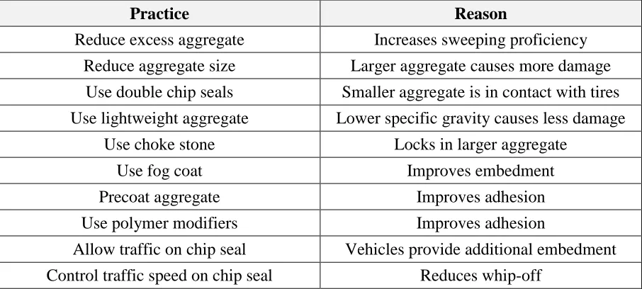
Table 1 Best Practices for Constructing High Volume Chip Seals (Gransberg and James 2005)
Practice Reason
Reduce excess aggregate Increases sweeping proficiency
Reduce aggregate size Larger aggregate causes more damage
Use double chip seals Smaller aggregate is in contact with tires
Use lightweight aggregate Lower specific gravity causes less damage
Use choke stone Locks in larger aggregate
Use fog coat Improves embedment
Precoat aggregate Improves adhesion
Use polymer modifiers Improves adhesion
Allow traffic on chip seal Vehicles provide additional embedment
Control traffic speed on chip seal Reduces whip-off
Table 1 shows that in addition to the use of PME to improve adhesive performance,
other valuable construction methods exist that can benefit the performance of chip seals at
high volumes, such as the use of lightweight aggregate or a reduction in aggregate size. From
the literature review (Shuler 1990) it is found that sweeping is also an essential aspect of chip
seal construction at high volumes. Sweeping becomes even more essential for high speeds. It
is recommended that the road surface is swept before being opened to traffic after
construction.
It is also found that chip seals perform well on high-volume roads when used as a
preventive maintenance tool on roads where the distress level is determined to be moderate,
at worst, and where the pavement condition rating is used as the threshold to determine when
a pavement needs to be surfaced using a chip seal treatment (Gransberg and James 2005).
Furthermore, at high traffic volumes the adhesion and bond between the aggregate
and emulsion become even more pivotal. It is suggested that aggregate-binder compatibility
is tested in a laboratory setting before construction even begins to ensure that the
Temperature is also an essential factor of adhesion and subsequent chip seal
performance. If the pavement temperature is too low during the emulsion application period
of construction, poor bonding between the aggregate and emulsion may be evident. This
situation is remedied either by constructing the pavement within an appropriate temperature
range, or using low temperature PMEs, such as those tested and developed by Road Science,
LLC. The Road Science research team constructed a chip seal on a day in March when the
temperature was below 50°F, which is below the temperature suggested in chip seal
construction guidelines. For this construction, the Stylink Low Temperature Emulsion Seal
Coat, specially developed by Road Science, was used. The Road Science team reported
proper curing and adhesion even at these low temperatures (Road Science 2009).
Road Science has developed additional equipment to help address the importance of
the time that elapses between spraying the emulsion and spreading the aggregate during chip
seal construction. Effectively, by controlling and limiting the time between the emulsion
being sprayed and the aggregate being spread, Road Science is able to ensure that the
bonding between the aggregate and emulsion is not hindered by cold emulsion that has
cooled during the time gap. The justification behind the development of such a machine is
that this time gap between spraying and spreading is even more critical at high volumes and
high speeds because poor aggregate retention is more likely to endanger drivers and damage
windshields at high speeds.
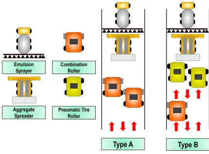
Kim et al. (2008) suggest optimum rolling patterns in chip seal construction based on
the results from aggregate retention performance tests and visual observation. They
recommend the use of both the pneumatic roller and combination roller to improve chip seal
performance. With regard to order, rolling should start with the pneumatic tire roller and
finish with the combination roller to produce a smooth surface. The optimal number of
spreading affects aggregate retention performance. Based on the findings, two optimum
rolling patterns are recommended for chip seal construction. According to the type A rolling
pattern, two combination rollers with three coverages are used to compact the entire lane
width. For the type B rolling pattern, two pneumatic tire rollers are used to apply three
coverages to the entire lane width, and then the combination roller, as a third roller, is
employed to apply an additional coverage on the section. The advantage of type B is that it
allows more coverages (four coverages in type B versus three coverages in type A) within the
same amount of rolling time. In addition, type B can fully capture the ability of both the
pneumatic tire roller that rolls the uneven surface of the existing pavement and the
combination roller that provides a smooth surface. Figure 2 shows the schematic rolling
patterns.
Figure 2 Rolling patterns
Emulsion
Sprayer Combination Roller
Pneumatic Tire Roller Aggregate
Spreader
Aggregate gradation is one of the most important factors that affect chip seal
performance. The performance uniformity coefficient (PUC) can be used to compare the
effects of different aggregate gradations. The closer the PUC is to zero, the more uniform is
the gradation of the aggregate source. In the Kim et al. (2011) study, three different
gradations of both granite 78M and lightweight aggregate were used to make specimens, and
then MMLS3 aggregate loss and bleeding tests were conducted. Based on the test results,
more uniform gradations (i.e., low PUC values) lead to better performance (i.e., less
aggregate loss and bleeding) than less uniform gradations (i.e., high PUC values) (Kim et al.
2011).
The Minnesota DOT (MNDOT) is one of the most expert agencies in seal coat
construction. Its publication, Minnesota Seal Coat Handbook 2006, includes bituminous seal coat specifications. The following summary of the use of modified chip seals on high-volume
roadways is based on these specifications (Section 2356 Bituminous Seal Coat), which were
revised most recently in 2008, and based also on personal email discussions with Mr.
Thomas J. Wood, Research Project Supervisor at the MNDOT
First of all, traffic volume is an important issue in chip seal construction. In
Minnesota, single seals can be constructed comfortably up to 15,000 ADT. Also, single-seal
construction is scheduled on roads with 30,000 ADT. Currently, the MNDOT does not have
restrictions on traffic level for single-seal construction. In order to achieve good performance,
chip seals typically are constructed on new hot mix asphalt (HMA) pavement no more than
four to five years after HMA pavement construction.
The MNDOT specifications recommend only CRS-2P emulsion, which is produced
with polymer-modified base asphalt, for high-volume chip seal construction. CRS-2P
emulsion is used for all high-volume roadways, whereas CRS-2L emulsion (latex-modified)
For seal coat construction, the use of quality aggregate is important. Sound and
durable particles of crushed stone or gravel typically are used. The MNDOT specifications
recommend the use of clean, uniform-sized aggregate particles that are free from wood, bark,
roots and other deleterious materials. In order to measure the flatness of the aggregate
particles used in chip seals, the so-called flakiness index (FI) is employed. The MNDOT specifies the use of aggregate with a maximum 25% FI and average 12% FI. Lightweight
aggregate is not used in Minnesota because single seals are commonly used for seal coats.
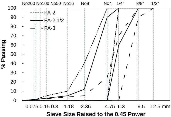
The gradations of FA-2, FA-2 1/2, and FA-3 are commonly used for chip seal treatments in
Minnesota; these gradations are plotted in Figure 3.
Figure 3 Aggregate particle size gradation in Minnesota: FA-2, FA-2 1/2, and FA-3
The single seal is used exclusively in seal coats even for high-volume roadways, and
a fog seal is applied on all chip seals the next day after the sweeping procedure. In general,
diluted CSS-1 or CSS-1h emulsions with a dilution rate of 50% are applied with rates of 0.07
to 0.12 gal/yd2 (0.32 to 0.54 L/m2) for chip seals. 0
10 20 30 40 50 60 70 80 90 100
0.0 0.5 1.0 1.5 2.0 2.5 3.0 3.5
%
P
a
s
s
ing
Sieve Size Raised to the 0.45 Power
FA-2 FA-2 1/2 FA-3
No200 No100 No50 No16 No8 No4 1/4" 3/8" 1/2"
However, double seals can be used on heavily cracked roads. Because double seals
are more susceptible to bleeding with choking stone (Virginia #9) on the surface, the
emulsion application rate (EAR) of the second layer should be cut down sufficiently. If a
single seal cannot achieve its design specifications properly, then second and third layers of
aggregate can be added to the seal to attain the desired performance.
In chip seal construction, several different types of rollers are used; these include the
pneumatic tire roller, steel wheel roller, vibratory steel wheel roller, rubber-coated vibrating
drum roller, and combination roller. Currently, the MNDOT specifications recommend only
pneumatic tire rollers in chip seal construction. A minimum number of three pneumatic tire
rollers is required for a 12-foot lane, and three passes are applied for the full paving width. In
order to achieve adequate compaction, the roller should be applied to the surface
continuously, and below 5 mph is the recommended speed for the rollers.
Sweeping is conducted within 20 minutes of compaction. After 20 minutes, a pilot car
traveling below 10 mph leads traffic across the fresh seal, and a sweeper (at a low-sweep
intensity setting) follows the pilot car and traffic. This process that combines the use of the
pilot car and sweeper continues with the sweeper’s intensity increasing as the number of
sweep passes increases. The early, slow (below 10 mph) traffic helps to embed and reorient
the aggregate particles of the chip seals. Also, early light sweeping removes excess aggregate
effectively, mainly from the area outside the wheel path, but also from the wheel path.
Traffic control remains in place throughout the day of construction. The final sweep is
applied the next morning. Up to three brooms are commonly used for the sweeping
procedure.
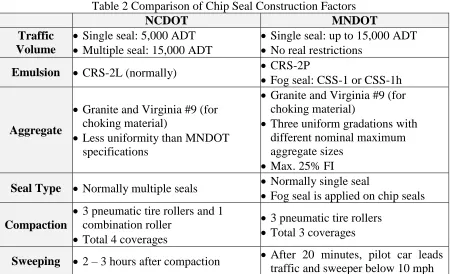
The construction procedure for modified chip seals in Minnesota indicates a few
differences from the chip seal construction procedure used by the NCDOT. Table 2 presents
Table 2 Comparison of Chip Seal Construction Factors
NCDOT MNDOT
Traffic Volume
Single seal: 5,000 ADT
Multiple seal: 15,000 ADT
Single seal: up to 15,000 ADT
No real restrictions
Emulsion CRS-2L (normally) CRS-2P
Fog seal: CSS-1 or CSS-1h
Aggregate
Granite and Virginia #9 (for choking material)
Less uniformity than MNDOT specifications
Granite and Virginia #9 (for choking material)
Three uniform gradations with different nominal maximum aggregate sizes
Max. 25% FI
Seal Type Normally multiple seals Normally single seal
Fog seal is applied on chip seals
Compaction
3 pneumatic tire rollers and 1 combination roller
Total 4 coverages
3 pneumatic tire rollers
Total 3 coverages
Sweeping 2 – 3 hours after compaction After 20 minutes, pilot car leads traffic and sweeper below 10 mph
2.6
The Use of Modified Chip Seals for Increased Traffic Volume Roads
2.6.1 Modified Chip Seals for Higher Traffic Volume Roads
At one time, the prevailing assumption was that chip seal surface treatments are not
adequate for high-volume roads. Now, with an improved understanding of the mechanics
behind chip seal performance, as well as improved material alternatives and construction
procedures, chip seal surface treatments are considered a viable option if designed and
constructed properly, even on high-volume roads.
For example, the Washington State DOT has been using chip seals successfully on
the deck of the Tacoma Narrows Bridge for years. This particular bridge has an ADT count
of 178,000. Additionally, Caltrans (the California Department of Transportation) uses chip
seals on I-5 and I-80, which are high-volume roadways, and has not had major issues with
Specifically, the CCSA provides guidelines for designing and constructing chip seals
that perform well on high-volume roads. To ensure chip retention early in the life of the chip
seal, the CCSA suggests using polymer-modified emulsion and waiting for appropriate
climate conditions. It also suggests that fog seals can be used to hold chips in place at high
traffic levels when necessary.
Schuler (1990) reports that chip seals used on high traffic volume roads in excess of
5,000 vehicles per day experience an average performance life of six to seven years, with
some chip seals lasting much longer. His study goes on to describe reasons for chip seal
failures on high-volume roads and details the methods used to overcome those problems.
Specifically, Shuler describes a method for predicting the potential adhesive ability of chip
seal emulsions by using a modified Vialit testing procedure.
In the NCHRP Chip Seal Best Practices (Gransberg and James 2005), it is noted that
California, Colorado, and Montana regularly construct chip seals on roads with ADT counts
that exceed 20,000 vehicles. It is reported that these chip seals perform either good or
excellent under these traffic conditions. Texas also has had success constructing chip seals on high-volume roads. It is noted that the chip seals that perform well tend to be
polymer-modified seals. As stated previously, PME has better adhesion than unpolymer-modified emulsion,
which helps the retention of aggregate at high traffic volumes and speeds (Kuennen 2005).
Gransberg and James (2005) report that in South Dakota chip seals using unmodified
polymer perform poorly in high-volume/high-speed road applications. Aggregate retention
was found to be the problem associated with most of the seal failures, with broken
windshields cited in many cases. The South Dakota DOT then embarked on a research effort
to determine the specific factors that could improve the performance of chip seal surface
treatments on high-volume roadways. In this study, twelve chip seal designs were used to
on high-volume roads by using PME. As previously mentioned, they reported adhesive
benefits as the main factors behind the improved performance.
Zaniewski and Mamlouk (1996) report that some agencies use PME in the design of
chip seals, particularly on high-volume roadways, because the polymer modification reduces
temperature susceptibility, provides increased adhesion to the existing surface, and allows the
road to be opened to traffic earlier than would ordinarily occur.
2.6.2 Fog Seal Application
2.6.2.1 Fog Seal General
Fog seals have been used as an effective means of preserving pavements for many
years. Fog seals are a method to ‘lock in’ aggregate by placing a light application of a
diluted asphalt emulsion over a chip seal. To achieve this seal, the fog seal emulsion must
fill the voids in the surface of the existing pavement. The fog seal emulsion also must
have sufficiently low viscosity so as not to break before it penetrates the surface voids of
the chip seal pavement during the fog seal application. A slow-setting emulsion that is
properly diluted with water is used for a fog seal. An improperly diluted emulsion may
not adequately penetrate the chip seal voids, resulting in excess asphalt on the surface of
the pavement after the emulsion breaks, which can result in a slippery surface (California
DOT 2003). Fog seals should not be used when a pavement has poor surface texture,
large cracks, rutting, shoving, structural deficiencies or low friction numbers (King et al.
2007).
The purpose of the fog seal is to improve aggregate retention and extend the service
life of the pavement by increasing the pavement’s impermeability to water and air. Also,
small cracks can be sealed by a fog seal application (Wood et al. 2006). For a proper fog seal
application, the existing pavement surface must be clean and dry. As part of a new chip seal
application, the fog seal should be applied immediately after sweeping. To be effective, fog
seals need to form a cohesive film once the water evaporates from the emulsion. This