Features of two-phase flow in a microchannel of
0.05×20 mm
Fedor Ronshin1,2*
1Kutateladze Institute of Thermophysics, 630090, 1 Acad. Lavrentiev ave., Novosibirsk, Russia 2Novosibirsk State University, 630090, 2 Pirogov st., Novosibirsk, Russia
Abstract. We have studied the two-phase flow in a microchannel with cross-section of 0.05×20 mm2. The following two-phase flow regimes have been registered: jet, bubble, stratified, annular, and churn ones. The main features of flow regimes in this channel such as formation of liquid droplets in all two-phase flows have been distinguished.
1 Introduction
Miniaturization of devices in various fields of technology, such as aerospace, electronics, transport, power engineering and medicine significantly increases the interest in hydrodynamics of gas-liquid flow and heat transfer in microsystems and microchannels. The studies show that heat exchange systems of mini- and microsizes are more energy efficient than macrosystem with free-flow of liquid [1-3] or a typical channel size greater than 1 mm [4].
The review on the regimes of two-phase flows in the channels of different geometries under different conditions is presented in [5, 6]. It is shown that the boundaries between the regimes differ significantly depending on the experimental conditions. According to analysis, the structure of two-phase flow is mainly influenced by the following parameters: channel geometry and dimensions, parameters of the inlet section and liquid properties such as viscosity and surface tension. In [7-9], the influence of the inlet section on the two-phase flow structure is analyzed, and it is shown that the conditions of gas and liquid input affect substantially the borders of two-phase flows in microchannels. The flows in the rectangular channels of various heights and widths are compared in [10-12]. It has been determined that the height and width of the horizontal microchannel affect substantially the boundaries between the flow regimes in a microchannel. The mechanisms that influence the formation of two-phase flow are studied in [11, 12]. Two new types of instability (frontal and lateral), responsible for the flow regime formation in microchannels depending on the channel sizes and liquid and gas flow rates, are distinguished.
The work deals with the studies of the features of two-phase flow in a short (the length from the liquid inlet to the microchannel is 90 mm) rectangular horizontal microchannel with the cross-section of 0.05×20 mm2.
2 Experimental setup and results
The test section consists of two parallel plates with the length of 160 mm and width of 55 mm (the upper plate is of glass, the lower plate is of stainless steel); the distance between them is set by two constantan strips with the height of 50 µm. A nozzle is made in the bottom plate at the angle of 11° made, and liquid is fed in-between the plates through this nozzle via a precision syringe pump. Microchannel dimensions are as follows: length is 160 mm, width is 20 mm, and height is 50 µm. The gas mixture is fed into the central part of the microchannel. The gas flow is regulated and maintained constant by the El-Flow flow controller of Bronkhorst company. After the assembly, the microchannel height has been measured at several points using the confocal technique. The average microchannel height in the observation area is 48.7 ± 5.3 µm.
The liquid flow rates have been ranged from 0.5 to 50 ml/min, gas flows have been varied from 100 to 5000 ml/min. Superpure distilled deionized nano-filtered water, pre-cleared by Direct-Q® 3 UV installation, have been used as liquid. High-purity nitrogen have been used as gas. The distance between the gas and liquid nozzle has been about 70 mm. The pressure in the gas chamber is measured by the pressure sensor WIKA Type P−30. The readings of this pressure sensor and current flow rate of gas are written in a file on a PC. Liquid and gas interaction in the microchannel have been visualized by the digital video and photocameras in the mode of Schlieren photography. The Schlieren method is used to register and visualize deformation of a thin liquid film surface. The detailed description of the Schlieren technique is presented in [13].
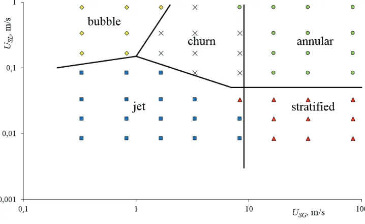
The following regimes of two-phase flow have been registered during the experiment: jet, bubble, stratified, annular, and churn ones. The regime map has been plotted, Fig. 1. Superficial velocities of liquid and gas, determined as the ratio of volumetric flow rate to cross-sectional area of the channel, have been used as the coordinates.
Fig. 1. Regime map in microchannel with cross-section of 0.05×20 mm2.
2 Experimental setup and results
The test section consists of two parallel plates with the length of 160 mm and width of 55 mm (the upper plate is of glass, the lower plate is of stainless steel); the distance between them is set by two constantan strips with the height of 50 µm. A nozzle is made in the bottom plate at the angle of 11° made, and liquid is fed in-between the plates through this nozzle via a precision syringe pump. Microchannel dimensions are as follows: length is 160 mm, width is 20 mm, and height is 50 µm. The gas mixture is fed into the central part of the microchannel. The gas flow is regulated and maintained constant by the El-Flow flow controller of Bronkhorst company. After the assembly, the microchannel height has been measured at several points using the confocal technique. The average microchannel height in the observation area is 48.7 ± 5.3 µm.
The liquid flow rates have been ranged from 0.5 to 50 ml/min, gas flows have been varied from 100 to 5000 ml/min. Superpure distilled deionized nano-filtered water, pre-cleared by Direct-Q® 3 UV installation, have been used as liquid. High-purity nitrogen have been used as gas. The distance between the gas and liquid nozzle has been about 70 mm. The pressure in the gas chamber is measured by the pressure sensor WIKA Type P−30. The readings of this pressure sensor and current flow rate of gas are written in a file on a PC. Liquid and gas interaction in the microchannel have been visualized by the digital video and photocameras in the mode of Schlieren photography. The Schlieren method is used to register and visualize deformation of a thin liquid film surface. The detailed description of the Schlieren technique is presented in [13].
The following regimes of two-phase flow have been registered during the experiment: jet, bubble, stratified, annular, and churn ones. The regime map has been plotted, Fig. 1. Superficial velocities of liquid and gas, determined as the ratio of volumetric flow rate to cross-sectional area of the channel, have been used as the coordinates.
Fig. 1. Regime map in microchannel with cross-section of 0.05×20 mm2.
At very low superficial liquid velocities, gas moves in the central part of the microchannel, and the bulk of liquid moves at the periphery along the sidewalls and as the jets in the center of microchannel. In microchannels higher than 100 microns, liquid flows
only along the sidewalls of microchannel [11]. With increasing superficial liquid velocity, it starts occupying a larger part of microchannel, and a gas flow moves in the center. Disturbances on the surface of the liquid are not observed. The stationary jet flow is observed at low superficial liquid and gas velocities, when the gas flow occupies less than a half microchannel width. The jet regime is specific for the flat mini- and microchannels. An increase in the superficial velocity of liquid leads to an increase in pulsation frequency and amplitude, and loss of stability of the jet regime of the two-phase flow. At low superficial velocities of gas, the amplitude of liquid perturbations in the lateral parts of microchannel reaches its half, forming the stable liquid bridges, and the slug or bubble flow starts.
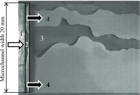
Fig. 2. Picture of the jet flow at USG = 0.333 m/s, USL= 0.017 m/s, top view.
1 – gas inlet to microchannel, 2 – slot in the bottom wall of microchannel for liquid input, 3 – unwetted zone on the upper wall of microchannel, 4 – liquid.
white arrow – direction of gas flow, black arrows – direction of liquid motion.
Figure 2 shows the jet flow at USG = 0.333 m/s, USL= 0.017 m/s. Liquid occupies a greater volume than gas. Under this regime, the motion of a gas jet in the microchannel center and along one wall is observed. Such asymmetry can be caused by inhomogeneity in the inlet region. In the channels of a greater height, liquid spreads along the sidewalls due to the effect of capillary forces. In the studied microchannel, liquid does not always spread along the walls; this can be caused by a large height to width ratio. By increasing the superficial gas velocity to USG = 1.667 m/s, the volume occupied by liquid, decreased significantly. Several liquid jets move in the microchannel. The motion of liquid droplets is also observed in the microchannel. With an increase in the superficial gas and liquid velocities, intensity of droplet formation increases, and the flow pattern becomes more complicated. After the passage of liquid droplets, a thin liquid film stays on the microchannel walls.
increasing gas and liquid velocities to USG = 0.833 m/s, USL = 0.333 m/s, the frequency of bubbles formation increases, they move along the left and right walls of the microchannel, and stationary small bubbles are observed in the middle.
At low superficial liquid velocities and high superficial velocities of gas, the stratified regime is observed. Under this regime, a part of liquid moves along the bottom wall of the microchannel in the form of a film entrained by a gas flow. The upper wall of microchannel is dry. Gas under this regime occupies more than a half microchannel cross-section. The stratified regime is characteristic only of the non-circular microchannels because in the circular microchannels the film closes, forming the annular flow. At USG = 16.667 m/s,
USL = 0.017 m/s, gas moves in the microchannel center, occupying the most part of its cross-section. The liquid droplets move along one of the microchannel sidewalls, leaving the traces on the liquid film. On the other side of microchannel, the film is not formed and droplets do not move. We can distinguish two kinds of droplets: large ones with the diameter of 1 to 3 mm, which represent the liquid bridges between the top and bottom walls of microchannel, and small droplets with the diameter of several micrometers on the microchannel wall or on the liquid film. With increasing superficial gas and liquid velocities to USG = 83.333 m/s, USL= 0.0833 m/s, the number of formed droplets is considerably smaller. The liquid film (sometimes with moving liquid droplets, which leave the traces) moves along the bottom wall of microchannel. Under this regime, the stationary droplets are not observed.
Fig. 3. Shlieren images (a) of the annular flow at USG = 83.333 m/s, USL= 0.667 m/s, (b) churn flow at USG = 6.667 m/s, USL= 0.5 m/s, top view.
1 – gas inlet to microchannel, 2 – slot in a lower wall of microchannel for liquid input,
3 – channel zones filled with liquid, 4 – film on the lower wall of microchannel, 5 – film on the upper wall of microchannel.
White arrow – direction of gas flow, black wall – direction of liquid flow.
With increasing superficial liquid velocity, the film is formed on the upper wall of microchannel, and transition to the annular regime occurs. Under this regime, we can see the mobile liquid droplets that slide over the liquid films on the top and bottom walls of microchannel. The transition from the stratified to the annular flow regime is determined using the Schlieren method. In the annular regime, liquid moves along the microchannel walls in the form of a film; in the central part, gas with droplets forms the flow core. Gas takes up much more volume than liquid. The liquid film is formed on the top wall of microchannel at a distance of several millimeters from the zone of liquid input to the microchannel. In previous experiments, in the microchannel with the height of less than 200 µm, the film has been formed on the top wall of microchannel directly near the liquid input into the microchannel due to frontal instability [11]. Figure 3a represents the annular regime at USG = 83.333 m/s, USL= 0.667 m/s. It can be seen that under this regime, the main part is occupied by the gas core with liquid droplets of a complex shape, the liquid film on
the upper wall is firstly formed in the side parts of microchannel, and then in the center. It has been possible to register the film on the bottom (4) and upper (5) walls of the microchannel. It can be seen that the film on the top wall of microchannel is formed at a distance of several millimeters from the liquid nozzle. Liquid droplets (3) move over the films in the microchannel, leaving the characteristic traces on the liquid film.
For the superficial velocities of liquid from 0.1 to 1 m/s and superficial gas velocities from 1 to 10 m/s, the churn flow is observed. This regime is characterized by the features of the jet and bubble flows. This mode is characteristic of the vertical channels, and it occurs in the wide horizontal microchannels. The broken bridges are typical of this regime. The churn flow is caused by development of jet flow instability and increasing pulsation frequency of liquid, moving near the sidewalls of microchannel under the influence of the gas flow. Both gas flow (with discontinuity) and gas bubbles can be seen in Fig. 3b. Formation of a liquid film on the bottom wall of microchannel (4) and formation of regions, where liquid fills the entire height of the channel (3), can be observed near the microchannel inlet. Film formation on the top wall of the microchannel (5) can be seen at a distance of a few millimeters from the liquid nozzle, gas bubbles are formed there. The churn flow occupies a significant area on the map (Fig. 1). The transition from the bubble (solid liquid-filled bridges) to the churn flow is accompanied by breakdowns of bridges. Vice versa, the transition from the jet to the churn flow is accompanied by formation of filled bridges, which are stable and their number exceeds one in the microchannel. At transition to the annular flow, the continuous liquid-filled bridges disappear.
In conclusion, it should be noted that in the channel of rectangular cross-section with the height of 50 µm and width of 20 mm, the liquid film has been registered on in the lower and upper walls of the microchannel. Such features of the two-phase flow as droplet formation under all regimes have been determined. Several kinds of droplets have been distinguished: moving and sessile droplets, the large droplets with the diameter from 1 to 3 mm in the form of the liquid bridge between the upper and lower walls of microchannel, and small droplets with the diameter of several micrometers on the microchannel walls or on the liquid film.
The study was supported by the grant of Russian Science Foundation (Agreement no. 14-19-01755).
References
1. E. A. Chinnov, Journal of Heat Transfer 138, 9 (2016)
2. E. A. Chinnov, E. N. Shatskii, High Temperature 52, 461 (2014) 3. E. A. Chinnov, E. N. Shatskiy, Tech. Phys. Lett. 40, 7 (2014)
4. V. V. Zamashchikov, A. A. Korzhavin, E. A. Chinnov, IJHMT 102, 470 (2016) 5. E. V. Rebrov, Theor. Found. Chem. Eng. 44, 355 (2010)
6. N. Shao, A. Gavriilidis, P. Angeli, Chemical Engineering Science 64, 2749 (2009) 7. V. Haverkamp, V. Hessel, H. Löwe et al., Chem. Eng. Technol. 29, 1015 (2006) 8. V. V. Cheverda, O. A. Kabov, Tech. Phys. Lett. 43, 293 (2017)
9. V. V. Cheverda, I. V. Marchuk, A.L. Karchevsky, E.V. Orlik, O.A. Kabov, Thermophysics and Aeromechanics 23, 415 (2016)
10. E. A. Chinnov, F. V. Ron’shin, O. A. Kabov, Tech. Phys. Lett. 41, 817 (2015) 11. E. A. Chinnov, F. V. Ron’shin, O. A. Kabov, Int. J. Multiphase Flow 80, 57 (2016) 12. E. A. Chinnov, F. V. Ron’shin, O. A. Kabov, Interfacial Phenomena and Heat
Transfer 3, 243 (2015)