228 | P a g e
A NEW IMPLEMENTATION OF AUTOMATED
SMART HOME CONTROL SYSTEM BY USING
LABVIEW 2014 TOOL
Thomas TeohZiEng
1, Mohammad Farook bin Rafiuddin
2,
Toong Chee Sheng
31,2, 3
Students in School of Computing, Asia Pacific University, (Malaysia)
ABSTRACT
Smart Home Control Systems also known as Home Automation, is the act of controlling basic home functions
through computer networks, both locally, remotely or even fully automated without the need of human
intervention. In this paper authors implemented a home based control system using Lab View 2014 tool. As
every system requires a framework for it to be built on, LabView is the program of choice for the designing and
implementation of the Smart Home Control System as it is capable of handling data input, processing and data
output from various types of signals and hardware. The completed system can also be hooked up to various I/O
devices that are supported and tested by LabView. In overall this paper provided the hardware integration of
smart home system.
Keywords: Control System, Automated, LabView, Smart Home, Network
I INTRODUCTION
Data Acquisition and Control concept refers to hardware and software solutions that are capable of receiving
input, making calculated measurements and transform them into actions which control external processes [1].
Data acquisition is the step where factors such as voltage, current, temperature, pressure or sound is measured
with a computer. Sensors pick up the analogue signal, sends them to the DAQ (Data Acquisition) device where
it is pre-processed and converted into digital signals to be read by the computer. One characteristic of the system
used further on in this project is split up into more than one modules, each having their specific function. In this
specific project, there are 4 modules, each serving its own purpose. Generally the modules are split into 2
groups, one being the module accepting inputs and the other, processing inputs and converting them into useful
processes that is required by the user. Having the modules separate also means that the modules handling the
processes can stay active even though the module to accept inputs are turned off when not in use. This translates
into a higher efficiency as less resources are required. Besides that, simple modules for receiving inputs allow
229 | P a g e
where the modules do not have to be located on the same computer to be used. Modules can be easily connected
through the internet where users are able to control the whole system remotely. National Instruments is an
organisation providing technology-based solutions for innovation and enhancing productivity. NI has helped
engineers and scientists remove complexity from their tasks, enabling them to carry out their tasks exceeding
expectations. Their solutions are implemented in a wide variety of industries, from consumer electronics to
particle physics, NI has the right hardware and software platform to improve the pre-existing solutions.
1.1 LABVIEW
LabVIEW or Laboratory Virtual Instrument Engineering Workbench, is a graphical programming environment
for visualizing, creating and coding engineering systems. Standing out from traditional text based programming
such as C, C++ and Java, the ability of being able to use graphics in creating solutions that are understandable
and easy to interpret by engineers have made LabVIEW become the top choice for engineers trying to transform
their ideas into reality. Being targeted at engineers, LabVIEW includes equipment and functions commonly
used in engineering labs. Engineers can then create a virtualized version of their systems before diving deep into
the physical system. In addition to the graphical user interface, the ability to drag-and-drop “Virtual
Instruments” (VI) into the programming interface greatly speeds up progress and keeps the programming code
clear and concise. By abstracting all the complicated low-level processing and removing the need of combining
different products to achieve the final solution, users are able to complete a whole system just by mastering
LabVIEW and deploying the system without worrying about compatibility issues that may arise with current
text-based programming paradigms. With LabVIEW, users are able to use a multitude of measurement and
control hardware across different brands with seamless integration. Lastly, LabVIEW also provides all internet
communication protocols which makes it the right tool for prototyping and deployment of Internet-of-Things
systems. A solid implementation of the common TCP/IP protocol ensures good connectivity between systems
and also ease of use for the end users.
1.2 FRONT PANEL
230 | P a g e
The front panel of a VI is also the user interface or the VI. Using various controls and indicators, the front panel
is built to allow input from users and also display of output processed by the VI. Controls that are present
include toggle switches, push buttons, radio buttons, knobs, numeric input, text input; indicators include LED
lights, numeric display, text display, graphs, animated pictures, and even ActiveX objects like Windows Media
Player. Controls work as input devices, supplying data into the block diagram of the VI. After processing by the
programming done in the block diagram, the indicators become output devices that display the outcome of the
operations done in the block diagram and shown in “Fig.1” [2].
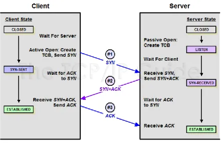
II. TCP/IP IN LABVIEW
TCP/IP stands for Transmission Control Protocol/Internet Protocol. It is a basic communication protocol used in
the Internet. It can also be used in a local area networks as long as the devices support this protocol. It allows
devices to send and retrieve data from other devices that also implement TCP/IP protocols.TCP/IP can be split
into two layers, with TCP being the higher layer and IP being the lower layer. The Transmission Control
Protocol is responsible of packing data into small packets to allow data transfer through the network. Internet
Protocol layer however, is responsible of handling addressing of each packet. Each router on the network will
check the address with a list of automatically updated tables and determine the direction of which the packet is
to be forwarded to and shown in “Fig.2”. Each packet does not have to follow a same route to the destination,
but each packet will be transferred sequentially [3].
231 | P a g e
The above figure shows a three-way handshake used in initiating TCP/IP connections, a SYN (synchronize)
packet is sent to the server, it returns another SYN accompanied by the ACK (acknowledgement) packet. The
client will then sent another ACK packet completing the process of establishing connection between the client
and the server. In LabVIEW the TCP/IP is implemented using various TCP/IP functions found in the TCP/IP
palette. It is located in Functions -> Data Communications -> Protocols -> TCP Palette in the block diagram of
LabVIEW. The TCP/IP functions in LabVIEW include TCP Listen, TCP Open Connection, TCP Read, TCP
Write, TCP Close Connection and more. This allows TCP/IP communication between separate VI instances and
over networks. TCP Open Connection function opens a TCP Connection with the address and remote port
provided to the function. It will try to establish connection to the server within the time set in “timeout” and
provides a connection ID to be used by other TCP functions such as TCP Write and TCP Read. The error out of
the function will output error codes to help diagnose problems with the connection.
III. SMART HOME FEATURES
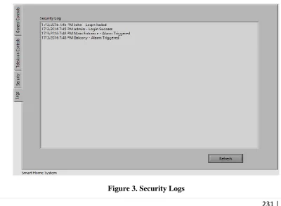
3.1 ALARM SYSTEM WITH LOGGING FEATURE
The alarm system implemented with the Smart Home control enables not only an alert to be triggered when an
attempted break-in occurs, but also log the details of the alert on a log.txt file to be reviewed by the home
owner. Login events (successful or failure) will also be included in the log files and displayed in the same
manner. Many have faced the problem where the alarm is active, but nobody is there to react or take preventive
measures to stop future thieves from fulfilling their wishes. The records on login details are used to deter
outsiders from trying to brute force the authentication system shown in “Fig.3”. Therefore the logging feature
implemented is to supplement the pre-existing alarm system to further improve safety of the home.
232 | P a g e
One major point in Smart Homes is the ability to save electricity and improve the quality of life. With motion
sensing light controls built in to the washroom lights, the lights will only turn on when someone is using the
washroom also shown in “Fig.4”. This is also very useful when a person is rushing to use the washroom, they do
not have to worry about turning on the lights and forgetting to turn then off afterwards.
Figure 4. Automatic Lights
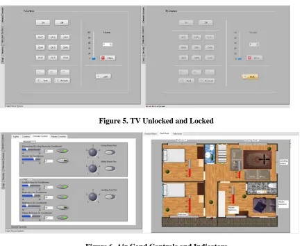
The TV Child Lock implemented with the TV controls are to prevent children from randomly pressing buttons
on the controls and thus causing the channel, volume or other settings to change while the user is enjoying
his/her favorite TV show and shown in “Fig.5”. The child lock will disable all buttons on the TV Control panel
but still allow other controls of the home to be modified, it only affects TV Controls.
Figure 5. TV Unlocked and Locked
233 | P a g e
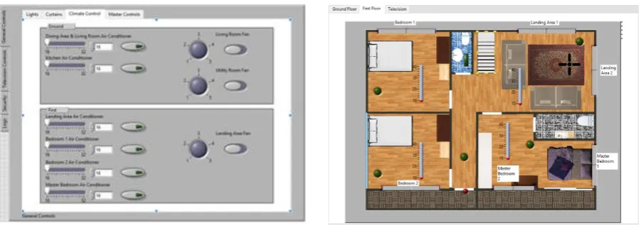
The air conditioning for the smart home is set up so that the temperature of the smart home stays at the
temperature set without going down further like traditional air conditioning systems. This is convenient to home
users not having to manually turn the air conditioning on or off based on the ambient temperature and also saves
electricity in the long run shown in the above “Fig.6”. The air conditioning will turn on as the temperature
exceeds the threshold set, and will turn off as the desired temperature is reached.
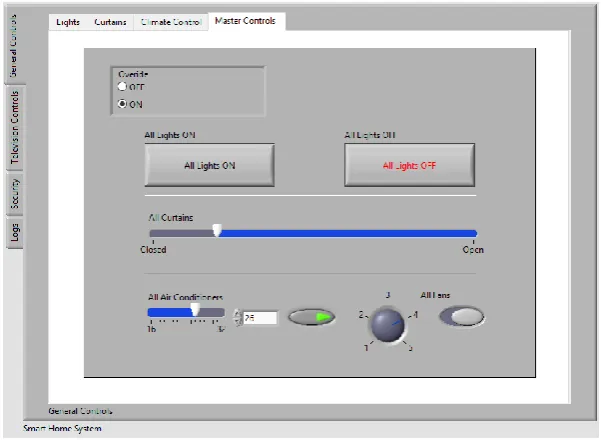
3.2 MASTER CONTROL
The master control panel is a set of settings used to control the settings of the whole smart home. Lights,
curtains, air conditioning, fans are all controlled from the master control. With a precautionary measure, users
are required to switch the radio control to “On” before the master control panel is activated. This smart home
system is deployed on the assumption that the control panel and server is running on the same computer. The
smart home system is also assumed to be running without any delay and reacts to requests instantly.The master
control panel is a set of settings used to control the settings of the whole smart home. Lights, curtains, air
conditioning, fans are all controlled from the master control. With a precautionary measure, users are required to
switch the radio control to “On” before the master control panel is activated shown in “Fig.7”.
Figure 7. Master Control Panel
IV. LIMITATIONS
As perfect as the system may be, there are still limitations to every system. In the smart home system, the server
must always be online for any appliance to work. If the power goes down, the home system would not work,
most essentially the alarm system. Without power, the alarm is not able to trigger and log down any activity to
the server log files. The system is not able to provide sound alerts due to a lack of codec support in the VI
environment. The security is only limited to break-in attempts and not including windows and motion detectors.
234 | P a g e
controls instead of a basic on/off or value selector is not able to be implemented in this smart home system. The
graphical user interface, while being clear and concise, fails to provide a programming interface that is compact
and easily reused for different objects. Therefore the smart home system lacks automation in terms of timed
light controls with light sensors, automatic fan controls and timed alarm systems.
V. FUTURE ENHANCEMENTS
In the future, the system can be improved by adding motion sensing equipment and cameras on the areas
surrounding the premise. The cameras can then be run for a set period of time after motion is detected to record
the face of the perpetrators. The files can also be saved in an archive, be viewed remotely and then be sent to the
relevant authorities for further action. The automation of lights and fans can be applied with the use of
light, humidity sensors. Instead of only using a time-based approach for the lights and fans, the data from the
sensors can also be used to calculate if the device should be turned on. This will further improve
eco-friendliness of the smart home. Air conditioning can also be turned off if there is nobody in the selected rooms.
Next up, the smart home should also include outdoor devices such as mailboxes and sprinklers. The owner will
then know when to pick up his mail and also automate the sprinklers to only activate when the water content in
the soil is low. RFID technology can also be implemented to the alarm system so that the house can
automatically unlock whenever the owner approaches the house. This will help in situations where it is not
convenient for the owner to pull out his phone to manually unlock the doors. RFID can also be used to automate
unlocking room doors based on each user’s specific RFID tag in their devices.All the electrical appliances can
be Wi-Fi-enabled to reduce the wiring cost and cost of implementing enterprise grade networking equipment.
With Wi-Fi, the appliances can be easily connected to the network without the need of tedious cable work.With
integration with Internet-Of-Things, the smart home system can be set-up to be more user-centric and change
controls based on Wi-Fi-enabled wearables such as heart rate sensor and blood pressure sensors. Smart homes
can manipulate the variables of the home environment to best suit the users’ mood and condition.
VI. CONCLUSION
In the grand scheme of things, this Smart Home Control System is successfully developed and is definitely
useful in making it convenient for the home owners to monitor and control functions in their house and provide
energy savings in the long run. The ability to control all the major functions in the home such as lights, climate
control, alarms, curtains are all embedded in this system that is completed in mere months. The intuitive user
interface that resembles classic controls will help new users especially the elderly as it is familiar to traditional
switches used. In the near future, Smart Homes will be a thing of norm in our society. For now, the only
obstacle preventing smart home industry from bursting into fame is the lack of applications that provide the ease
of use and seamless transition from a physical toggle to a touch screen control. (Tso, 2014) With LabVIEW, it is
possible to create a smart home system that is easy to use and with an easy learning curve.By automating many
of the functions in the home, it is possible to increase the efficiency of electric and water use, but at the same
235 | P a g e
time to ponder upon more critical issues than wasting time figuring out whether if the front door is locked.Last
but not least, a lot of continuous research is still required to expand smart homes and integrate
Internet-of-Things into smart homes. A cry for an open standard protocol for all appliances to inter-connect is present in the
world where brands try to monopolize the market with proprietary software and APIs. With the establishment of
a public open source standard and a platform for users to create their own interfaces, the adoption of smart
homes are sure to skyrocket in the future.
VII. ACKNOWLEDGEMENTS
The authors would like to say heartfelt thanks to Dr Jothi Sophia, Principal, CSI JACON, India for her constant
support and encouragement to publish this paper in International Conference, India.
REFERENCES
[1] Keithley Instruments, Inc., 2001. Data Acquisition and Control Handbook. [Online]
Available at:
https://fenix.tecnico.ulisboa.pt/downloadFile/3779571242401/Data%20Acquisition_KEYTHLEY.pdf
[Accessed 12 February 2016]
[2] National Instruments, 2000. Getting Started with LabVIEW. [Online]
Available at: http://www.ni.com/pdf/manuals/321527d.pdf, [Accessed 12 February 2016].
[3] Tech Target, 2008. What is Client-Server. [Online]