Toward the measurement of the hyperfine structure of
muonic hydrogen in the FAMU experiment.
Multi-pass cavity optimization for experiments with pulsed sources.
DimitarBakalov1,∗and MihailStoilov1,
1Institute for Nuclear Research and Nuclear Energy, Bulgarian Academy of Sciences, Tsarigradsko ch.
72, Sofia 1784, Bulgaria
Abstract.We consider a simplified model of the optical multi-pass cavity that is being currently developed by the FAMU collaboration for the measurement of the hyperfine splitting in the ground state of muonic hydrogen and of the Zemach radius of the proton. The model is focused on the time distribution of the events of laser-stimulated hyperfine transitions in the muonuc atom and may be helpful in the preliminary design of the FAMU experimental set-up and, more generally, in the optimization of multi-pass optical cavities for exper-iments with pulsed lasers.
1 Introduction
The laser excitation of the orthoS =1 hyperfine sub-level of the ground state of the muonic
hydrogen atom from the paraS = 0 sub-level (whereS = Sp+Sµ is the total spin of the
muonic hydrogen atom µ−p) is an ambitious project of the FAMU collaboration [1]: the
measurement of the resonance transition frequency will provide top-accuracy data on the Zemach radius of the proton[2]. This is a very weak M1 magnetic dipole transition with probability of only 2×10⁻⁵(E/J)(S/m2)−1(T/◦K)−1/2 for laser pulse energyE, laser beam
cross sectionS and target temperatureT [3], for which an optical multi-pass cavity needs to be used to enhance the probability of laser-stimulated transitions to a reasonable level.
The measurement of the hyperfine splitting in the ground state of muonic hydrogen con-sists in the detailed study of the chain of processes occurring when muonic hydrogen atoms in a mixture of hydrogen and oxygen interact with laser radiation tuned at a frequency around the hyperfine transition resonance frequency [3]. The observable quantity used as signature is the time distribution of the events of muon transfer from hydrogen to oxygen [4] recog-nized by the emission of characteristic X-rays : the maximal deviation of the latter from the background time distribution in absence of laser indicates that the laser source is tuned at the resonance frequency.
The FAMU experiment will use the pulsed muon source of the RIKEN-RAL muon facility [5], a tunable pulsed mid-infrared laser in the 6.8µm range [6], and a multi-pass cavity with mirrors of very high reflectance. The work on the optimization of the experimental set-up showed that in experiments with pulsed sources the time distribution of the laser energy in the multi-pass cavity is of primary importance. We present here a simplified model of the
phenomena in this case that allows to qualitatively determine the optimal parameters of the cavity in dependence of the laser pulse parameters. Particular attention is paid to the optimal choice of the measurement time gate, i.e. the time interval in which the time distributions of the characteristic X-rays with and without laser are to be observed.
2 Modelling the time profile of the electromagnetic fields in a
multi-pass cavity
2.1 Preliminary remarks
The probabilitydpfor the excitation of the ortho hyperfine ground state ofµ−pwith a
oscil-lating magnetic field of resonance frequencyν0in the time intervaldtsuch thatν0dt ≫ 1,
under the condition that the width of the laser line is smaller that the Doppler broadening of the hyperfine transition line, can be put in the form:
dp=K|B(r)|2dt (1)
whereB(r) is the amplitude of the magnetic field carried by the laser plane wave at the positionrof theµ−patom, and the value of the dimension coefficientKis expressed in terms
of the masses and magnetic moments of the proton and the muon, the temperature andν0[3]
K=
√
(mp+mµ)c2
32πkTν20
(
µB
(me
mpµp+ me mµµµ
))2
(2)
Accordingly, the probabilitydP that a para-to-ortho transition will occur in the elemental volumed3r(i.e. the expected number of laser-stimulated spin-flip events) is
dP=C(r)K|B(r)|2dt d3r, (3)
whereC(r) is the number density ofµ−patoms. At distances of the order of the wave length λ0 = c/ν0, the amplitudeB(r) itself varies much faster than the atomic densityC(r), so we
consider the probabilitydP¯, obtained fromdP by averaging over a volume ∆V such that ∆V≫λ30:
dP¯/dt= 1 ∆V
∫
∆V dP
dt d3r= K
∆V
∫
∆V
d3rC(r)|B(r)|2≈K C(r) 1
∆V
∫
∆V
d3r|B(r)|2=K C(r)|B(r)|2,
(4) where|B(r)|2is the amplitude of the magnetic field averaged at the wavelength scale. Denote
by N(t1,t2;V) the number of laser-stimulated spin-flip events that occur in the volume V
during the measurement time interval [t1,t2]:
N(t1,t2;V)=
t2 ∫
t1 dt∫
V dP¯
dt d3r=K t2 ∫
t1 dt∫
V
C(r)|B(r)|2d3r, (5)
and byN(t1,t2) – the number of events in the whole cavity (of which, in the general case, only
part of which is irradiated by the laser source). For uniform muonic atom densityC(r)=C0
this yields
N(t1,t2;V)=K C0
t2 ∫
t1 dt
∫
V
phenomena in this case that allows to qualitatively determine the optimal parameters of the cavity in dependence of the laser pulse parameters. Particular attention is paid to the optimal choice of the measurement time gate, i.e. the time interval in which the time distributions of the characteristic X-rays with and without laser are to be observed.
2 Modelling the time profile of the electromagnetic fields in a
multi-pass cavity
2.1 Preliminary remarks
The probabilitydpfor the excitation of the ortho hyperfine ground state ofµ−pwith a
oscil-lating magnetic field of resonance frequencyν0 in the time intervaldtsuch thatν0dt ≫ 1,
under the condition that the width of the laser line is smaller that the Doppler broadening of the hyperfine transition line, can be put in the form:
dp=K|B(r)|2dt (1)
where B(r) is the amplitude of the magnetic field carried by the laser plane wave at the positionrof theµ−patom, and the value of the dimension coefficientKis expressed in terms
of the masses and magnetic moments of the proton and the muon, the temperature andν0[3]
K=
√
(mp+mµ)c2
32πkTν20
(
µB
(me
mpµp+ me mµµµ
))2
(2)
Accordingly, the probabilitydP that a para-to-ortho transition will occur in the elemental volumed3r(i.e. the expected number of laser-stimulated spin-flip events) is
dP=C(r)K|B(r)|2dt d3r, (3)
whereC(r) is the number density ofµ−patoms. At distances of the order of the wave length λ0 =c/ν0, the amplitudeB(r) itself varies much faster than the atomic densityC(r), so we
consider the probability dP¯, obtained fromdP by averaging over a volume ∆V such that ∆V≫λ30:
dP¯/dt= 1 ∆V
∫
∆V dP
dt d3r= K
∆V
∫
∆V
d3rC(r)|B(r)|2≈K C(r) 1
∆V
∫
∆V
d3r|B(r)|2=K C(r)|B(r)|2,
(4) where|B(r)|2is the amplitude of the magnetic field averaged at the wavelength scale. Denote
by N(t1,t2;V) the number of laser-stimulated spin-flip events that occur in the volume V
during the measurement time interval [t1,t2]:
N(t1,t2;V)=
t2 ∫
t1 dt∫
V dP¯
dt d3r=K t2 ∫
t1 dt∫
V
C(r)|B(r)|2d3r, (5)
and byN(t1,t2) – the number of events in the whole cavity (of which, in the general case, only
part of which is irradiated by the laser source). For uniform muonic atom densityC(r)=C0
this yields
N(t1,t2;V)=K C0
t2 ∫ t1 dt ∫ V
|B(r)|2d3r. (6)
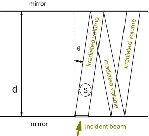
Figure 1.A schematic representation of the laser beam propagation in the optical multi-pass cavity. The distance between the two flat parallel mirrors isd; the beam incidence angle is
ϑ, and its cross section issL.
In a multi-pass cavity the oscillating magnetic fieldB(r,t) atris theincoherent sumof the magnetic fields carried by the multiple reflected laser beams that irradiate the pointr:
B(r,t)=∑
n
Bnexpi(kn.r−ω0t+δn)+c.c., (7)
whereBn,δnandknare the amplitude, phase and wave vector of then-th plane wave, all of them with the sameω0=2πν0and|kn|=k. It can be shown for two summands that|B(r)|2=
|B1|2+|B2|2+O((θk∆V)−1/3) (whereθis the angle betweenk1andk2,k1.k2=k2cosθ, and
∆Vis the smoothing volume of Eq.(4)); the latter is directly extended to any number of plane
waves crossing at non-zero angles:
|B(r)|2≈∑
n
|Bn|2 (8)
2.2 A simple mathematical model of the multi-pass cavity
We shall consider a simplified model of the multi-pass cavity aimed at qualitatively repro-ducing only thetimedependence ofN(t1,t2;V). The evaluation of thespatialdistribution of
the spin-flip events requires specific simulation codes and the detailed knowledge of theµ−p -atom number density spatial distribution that are out of the scope of this talk; accordingly, we adopt the approximation of uniform number density of the muonic atoms, assumeVto be the wholecavity volume ¯V, and consider only the time distribution ofN(t1,t2)≡N(t1,t2,V¯).
We assume that the cavity consists of two parallel mirrors at distanced. The laser beam with cross sectionsLis injected in the cavity at incidence angleα(see Fig. 1) and is multiply reflected by the mirrors of reflectanceR. The details of the curved mirror edges that force the beam not to leave the cavity volume are not considered at all. The irradiated volume V∗ ∈ V may be thought to consists of cylindric segments with base surface sL and height d/cosα ≈ d for incidence angles α ≪ π/2; the time light travels through a segment is approximatelyτd =d/c. We assume that the target gas is perfectly transparent for the laser light, so that|B(r)|2 does not vary along a segment (except for the zone of overlap of two
segments – an effect that can be accounted for at a later stage). At each reflection the value
Let the laser pulse of durationτLenter the cavity at timet0 =0, and the the value of the
averaged magnetic field at entrance be|B(r)|2=B2
0. Betweent=t0andt=τLthe irradiated
volumeV, as well as the number of eventsN(t0,t;V∗) increase monotonously: at eachτd a new segment is irradiated. The value ofN(t0,t;V) in this time interval is approximately
N(t0,t)=α
( c
1−Rt−d
R(1−Rtc/d) (1−R)2
)
, 0≤t≤τL, (9)
wherecis the speed of light and, for simplicity, we introduced the notationα=K C0B20sL.
After the end of the laser pulse, fort ≥τL, the irradiated spot propagates through the cavity but its volumeV remains unchanged, and after each reflection, i.e. at everyτd, the magnetic field in the segments is suppressed by the factorR, that leads to
N(τL,t)=α d (1−R)2
(
1−RcτL/d) (1−Rc(t−τL)/d), t≥τ
L. (10)
From hereN(0,t)=N(0, τL)+N(τL,t). For large measurement timest≫τd
lim
t→∞N(0,t)=
α
1−RcτL+
α
1−Rd (
1−RτL/τd) α
1−RcτL. (11) Without a multi-pass cavity, the number of laser-stimulated spin-flip events at the same phys-ical conditions would beN0 = K C0B20slc′, τL = αcτL. The “amplification effect” of the
multi-pass cavity is therefore described with the factor
A(t)=N(0,t)/N0 =(1−R)−1×
( 1+τd
τL (
1−RτL/τd) (1−(1−R)−1R(t−τL)/τd)), t≥τ
L, (12)
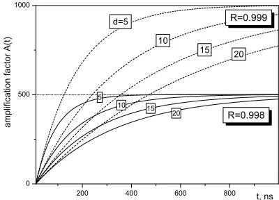
the whole dependence ontbeing hidden in the rightmost factor. Fig. 2 is a plot ofA(t) for the typical values of the parametersτL=20 ns,R=0.998 andR=0.999, and the set of values d=5(5)20 cm.
Figure 2.Amplification factorA(t) of the number of laser-stimulated spin-flip events in a multi-pass cavity as function of the
measurement timet, for laser pulse lengthτL=20 ns, mirror reflectance R=0.998 andR=0.999, and distance between the mirrorsd=5(5)20 cm.
3 Optimization of the measurement time gate
Eq. (11) gives the upper limit of the amplification factor:A(t)≃(1−R)−1; Fig. 2 shows that
Let the laser pulse of durationτLenter the cavity at timet0 =0, and the the value of the
averaged magnetic field at entrance be|B(r)|2 =B2
0. Betweent=t0andt=τLthe irradiated
volumeV, as well as the number of eventsN(t0,t;V∗) increase monotonously: at eachτda new segment is irradiated. The value ofN(t0,t;V) in this time interval is approximately
N(t0,t)=α
( c
1−Rt−d
R(1−Rtc/d) (1−R)2
)
, 0≤t≤τL, (9)
wherecis the speed of light and, for simplicity, we introduced the notationα=K C0B20sL.
After the end of the laser pulse, fort ≥τL, the irradiated spot propagates through the cavity but its volumeVremains unchanged, and after each reflection, i.e. at everyτd, the magnetic field in the segments is suppressed by the factorR, that leads to
N(τL,t)=α d (1−R)2
(
1−RcτL/d) (1−Rc(t−τL)/d), t≥τ
L. (10)
From hereN(0,t)=N(0, τL)+N(τL,t). For large measurement timest≫τd
lim
t→∞N(0,t)=
α
1−RcτL+
α
1−Rd (
1−RτL/τd) α
1−RcτL. (11) Without a multi-pass cavity, the number of laser-stimulated spin-flip events at the same phys-ical conditions would be N0 = K C0B20slc′, τL = αcτL. The “amplification effect” of the
multi-pass cavity is therefore described with the factor
A(t)=N(0,t)/N0=(1−R)−1×
( 1+τd
τL (
1−RτL/τd) (1−(1−R)−1R(t−τL)/τd)), t≥τ
L, (12)
the whole dependence ontbeing hidden in the rightmost factor. Fig. 2 is a plot ofA(t) for the typical values of the parametersτL=20 ns,R=0.998 andR=0.999, and the set of values d=5(5)20 cm.
Figure 2.Amplification factorA(t) of the number of laser-stimulated spin-flip events in a multi-pass cavity as function of the
measurement timet, for laser pulse lengthτL=20 ns, mirror reflectance R=0.998 andR=0.999, and distance between the mirrorsd=5(5)20 cm.
3 Optimization of the measurement time gate
Eq. (11) gives the upper limit of the amplification factor:A(t)≃(1−R)−1; Fig. 2 shows that
the time needed to reach the maximal amplification grows fast with the distancedbetween
mirrors and with the mirror reflectivityR. Knowing the explicit dependence of the number of spin-flip events on the measurement timetmay therefore help select the optimal measurement time gate [0,t] for which the number of laser-stimulated spin-flip events is maximal. In such
an optimization problem one should, of course, take into account the finite muon decay rate
λ0as well. As shown of Fig. 3, the muon decay partly suppresses the gain of laser-stimulated
spin-flip events due to the multi-pass cavity.
Figure 3.Modified amplification factor exp(−λ0t)A(t) of the number
of laser-stimulated spin-flip events in a multi-pass cavity as function of the
measurement timet, for laser pulse lengthτL=20 ns, mirror reflectance R=0.998 andR=0.999, and distance between the mirrorsd=5(5)20 cm.;
λ0=0.45µs−1is the muon
decay rate.
To optimize the efficiency of the FAMU experiment, however, one should maximize the
signal-to-noise ratio∆/σrather than just the number of laser-stimulated spin-flip events. In the experimental method of FAMU, the “noise”σ(also referred to as “background”) mainly consists of characteristic X-rays emitted during the relaxation of the µ−O atoms formed through muon transfer fromthermalizedmuonic hydrogen atoms (and therefore independent of the laser light), while the “signal”∆is the variation of the the background distribution due
to X-rays fromµ−Oatoms formed by muon transfer fromepithermalµ−H[3, 7]. Obviously, the latter is proportional to the number of laser-stimulated events, while the “noise” depends only on the number of muonic atoms in target:
∆∼exp(−λ0t)A(t), σ2 ∼
t ∫
0
exp(−λ0t′)dt′=(1−exp(−λ0t))/λ0, (13)
so that the time dependenceS(t) of the signal-to-noise ratio is:
S(t)=∆
σ ∼
exp(−λ0t)
√
1−exp(−λ0t))
A(t). (14)
The noiseσgrows monotonously with the durationtof the measurement time gate while the
signal∆reaches its maximum at some finite moment (see Fig. 3). We can therefore expect
S(t) to have pronounced maxima for any value ofdandR, that will determine the optimal time gate for measurement of the hyperfine splitting of muonic hydrogen in the FAMU approach.
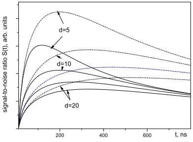
Fig. 4 confirms these qualitative predictions. We also note that:
• The maximal achievable signal-to-noise ratio is increased as the distanced between the mirrors decreases;
Figure 4.Dependence of the signal-to-noise ratio S(t)= ∆/σ(in arbitrary units) on the measurement time gatet, for a set of inter-mirror distances d=5(5)20 cm, mirror reflectivityR=0.998 (solid lines) orR−0.999 (dashed
lines), and laser pulse length
τL=20 ns.
4 Conclusions
The simplified model of the optical multi-pass cavity considered here completely neglects the effects of the spatial distribution of the muonic hydrogen atoms and of the laser radiation
throughout the cavity, as well as some other details of the undergoing physical processes, and cannot be directly applied in simulations of the FAMU experiment. Still, it reveals important peculiarities related to the use of multi-pass cavities in experiments with pulsed laser and muon sources, and can be helpful in the preliminary design of the experimental set-up and the approximate choice of the optimal measurement time gate and inter-mirror distance.
5 Acknowledgments
The authors acknowledge the support of Grant 08-17 of the Bulgarian Science Fund.
References
[1] https://webint.ts.infn.it/ricerca/exp/famu/
[2] A. Adamczak, G. Baccolo, D. Bakalov,et al., JINST 11, P05007 (2016). [3] A. Adamczak,et al., Nucl. Instrum. Meth.B 281, 72 (2012).
[4] E. Mocchiutti, V. Bonvicini, R. Carbone,et al., to appear in JINST (2017). [5] T. Matsuzaki,et al., Nucl. Instr. Meth. A 465 (2001) 365.
[6] L.Stoychev, M. Danailov, A. Demidovich, et al., Proc. SPIE 9135, Laser Sources and Applications II, 91350J (May 1, 2014); doi:10.1117/12.2052110