Harmonic Reduction of Enhanced Single Phase Step-Up
Five-Level Inverter Using Lcl Filter
Darzi Badai Ameer Suhail & Dr. K. Chithambaraiah Setty
1
Pg Student ,
2Associate Professor &Hod
Department Of Eee
St.Johns College of Engineering &Technology, Yerrakota,Yemmiganur,Kurnool ,Andhra Pradesh ABSTRACT
One of the important criteria is the quality and harmonic contents of the current being injected to the grid. High-order harmonics of the grid current should be very limited (lower than 0.3% of the fundamental current). Beside the topology of the power electronic interface, the output filter also affects the quality of the load voltage .proposed a 5-level inverter is presented for grid integration systems along with its output LCL filter design. Analytical calculation of losses for the 5-level inverter and the output LCL filter is presented. It is also compared to the H-bridge inverter in terms of output voltage and current harmonics, and the overall losses.
I.INTRODUCTION
1.1 GENERAL
In the past decade, renewable energy sources such as photovoltaic (PV)-based systems have attracted much more attention due to the advantages such as less environmental impact and improved economic benefits. With the rapid growth of power electronics technology, various converters topologies have been developed for PV systems. Among these topologies, multilevel inverters have been receiving significant interest due to the reduced total harmonic distortion (THD) and improved quality of output waveform. As the output voltage level increases, the output harmonic content of such inverters decreases, allowing the use of smaller output filters. For single-phase multilevel inverters, the most common topologies are the neutral-point-clamped (NPC).
1.2 SCOPE OF THE PROJECT
The scope of the project is used to enhance the stepped up five level inverter.
II. MULTI LEVEL INVERTERS
An inverter is an electrical device that converts direct current (DC) to alternating current (AC); the converted AC can be at any required voltage and frequency with the use of appropriate transformers, switching, and control circuits. Static inverters have no moving parts and are used in a wide range of applications, from small switching power supplies in computers, to large electric utility high-voltage direct current applications that
transport bulk power. Inverters are commonly used to supply AC power from DC sources such as solar panels or batteries. The electrical inverter is a high-power electronic oscillator. It is so named because early mechanical AC to DC converters were made to work in reverse, and thus were "inverted", to convert DC to AC.
2.1Cascaded H-Bridges inverter
A single-phase structure of an m-level cascaded inverter is illustrated in Figure 4.1. Each separate dc source (SDCS) is connected to a single-phase full-bridge, or H-bridge, inverter. Each inverter level can generate three different voltage outputs, +Vdc, 0, and –Vdc by connecting the dc source to the ac output by different combinations of the four switches, S1, S2, S3, and S4. To obtain +Vdc, switches S1 and S4 are turned on, whereas – Vdc can be obtained by turning on switches S2 and S3. By turning on S1 and S2 or S3 and S4, the output voltage is 0. The ac outputs of each of the different full-bridge inverter levels are connected in series such that the synthesized voltage waveform is the sum of the inverter outputs. The number of output phase voltage levels m in a cascade inverter is defined by m = 2s+1, where s is the number of separate dc sources. An example phase voltage waveform for an 11-level cascaded H-bridge inverter with 5 SDCSs and 5 full bridges is shown in Figure 4.2. The phase voltage
+
For a stepped waveform such as the one depicted in Figure 4.2 with s steps, the Fourier Transform for this waveform follows
Fig.1Single-phase structure of a multilevel cascaded H-bridges inverter
Fig.2 Output phase voltage waveform of an 11-level cascade inverter with 5 separate dc sources.
III. PROJECT DESCRIPTION
3.1 GENERAL
Overall, the abovementioned multilevel topologies only can realize the voltage step-down inversion,
weight and realizes the voltage step up . However, two dc sources and corresponding split of dc bus capacitors are required as well as more switches and diodes in. The step-up ratio of the boost converter has some limitations which restrict the step-up capability . A high stepup inverter is proposed in using the diode-capacitor cell and couple inductor.
3.2 MODULES NAME
multilevel inverter,
single phase
3.3 MODULE DESCRIPTION
multilevel inverter
Now a day’s many industrial applications have begun to require high power. Some appliances in the industries however require medium or low power for their operation. Using a high power source for all industrial loads may prove beneficial to some motors requiring high power, while it may damage the other loads. Some medium voltage motor drives and utility applications require medium voltage. The multi level inverter has been introduced since 1975 as alternative in high power and medium voltage situations. The Multi level inverter is like an inverter and it is used for industrial applications as alternative in high power and medium voltage situations.
The need of multilevel converter is to give a high output power from medium voltage source. Sources like batteries, super capacitors, solar panel are medium voltage sources. The multi level inverter consists of several switches. In the multi level inverter the arrangement switches’ angles are very important.
Multilevel inverters are three types.
o Diode clamped multilevel inverter
o Flying capacitors multilevel inverter
o Cascaded H- bridge multilevel inverter
single phase
Single phase AC power systems peak in voltage at 90° and 270°. A cycle completes at 360°. Because of the rises and falls in voltage, power is not delivered at a constant rate.
In contrast, in a three-phase system, the currents in each conductor reach their peak instantaneous values sequentially, not simultaneously; in each cycle of the power frequency, first one, then the second, then the third current reaches its maximum value. The waveforms of the three supply conductors are offset from one another in time (delayed in phase) by one-third of their period. When the three phases are connected to windings around the interior of a motor stator, they produce a revolving magnetic field; such motors are self-starting.
"The primary difference between single phase and three phase AC power is the constancy of delivery.
3.4 CIRCUIT EXPLANATION Modules Description: Circuit Diagram
3.5 MODES OF OPERARIONS:
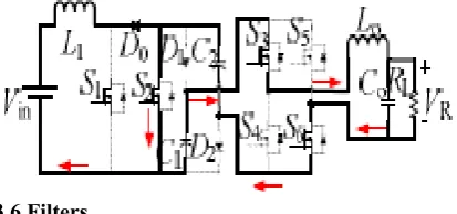
the working mode of the proposed five-level inverter. The red arrows in the figures show the current path. Overall, it can be seen that there are six switching states in each half-cycle. The operating modes of the positive half sinusoidal cycle (modes 1-6) are discussed in detail as below.
Mode 1 : S1 is turned ON in this mode. The inductor L1 is charged by the input dc source and the inductor current is increasing linearly. Meanwhile, the load current flows through S6 and anti-parallel diode of S4.
Mode 2: S1 is turned OFF in this mode. Diodes D0, D1 and D2 are all conducting. The inductor L1 is discharging and the input source is charging the diode-capacitor network. In this mode, the ac load current still flows through S6 and antiparallel diode of S4.
Mode 3 : S1 is maintained OFF and S3 is ON in this mode. Diodes D0, D1 and D2 are maintained ON. The input dc source charges the diode-capacitor cell and simultaneously provides the power to the load.
Mode 4 : S1 is turned ON again while D0 is turned OFF in this mode. L1 is charged by the input source and capacitors C1, C2 are working in parallel to feed the load.
Mode 6: S2 stays ON state and S1 is turned OFF in this mode. Similar as mode 5, the capacitors C1, C2 are connected in series supplying power to the ac load. Similarly, there are six working modes when the inverter outputs negative voltage
3.6 Filters
Filters of some sort are essential to the operation of most electronic circuits. It is therefore in the interest of anyone involved in electronic circuit design to have the ability to develop filter circuits capable of meeting a given set of specifications. Unfortunately, many in the electronics field are uncomfortable with the subject, whether due to a lack of familiarity with it, or a reluctance to grapple with the mathematics involved in a complex filter design.
In circuit theory, a filter is an electrical network that alters the amplitude and/or phase characteristics of a signal with respect to frequency. Ideally, a filter will not add new frequencies to the input signal, nor will it change the component frequencies of that signal, but it will change the relative amplitudes of the various frequency components and/or their phase relationships. Filters are often used in electronic systems to emphasize signals in certain frequency ranges and reject signals in other frequency ranges. Such a filter has a gain which is dependent on signal frequency. As an example, consider a situation where a useful signal at frequency f1 has been contaminated with an unwanted signal at f2. If the contaminated signal is passed through a circuit (Figure 1.4) that has very low gain at f2 compared to f1, the undesired signal can be removed, and the useful signal will remain. Note that in the case of this simple example, we are not concerned with the gain of the
general, however, a filter’s gain may be specified at several different frequencies, or over a band of frequencies. Since filters are defined by their frequency-domain effects on signals, it makes sense that the most useful analytical and graphical descriptions of filters also fall into the frequency domain. Thus, curves of gain vs frequency and phase vs frequency are commonly used to illustrate filter characteristics, and the most widely-used mathematical tools are based in the frequency domain.
FIGURE 3: Using a Filter to Reduce the Effect of an Undesired Signal at Frequency f2, while Retaining Desired Signal at Frequency f1. IV.TYPES OF FILTERS
The power system must be free from harmonics and which will lead to numbers of benefits. A clean network has less strain on appliances and their lifespan are lengthened. Maintenance and replacement costs are lowered. So we go for filters. Filters can be classified into three types:
1. Active filter 2. Passive filter 3. Hybrid filter
PASSIVE FILTERS
Passive harmonic filters consisting of capacitors, inductors, and resistors can be classified into
(i) Tuned filters
(ii) High pass filters.
Tuned filters:
Fig 4 A single tuned filter.
Fig. shows a Single tuned filter having series connection of a capacitor, an inductor, a resistor and separate out a single frequency harmonic.
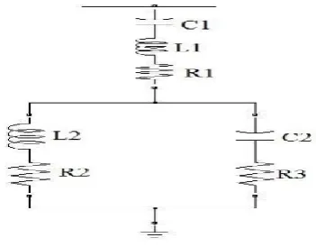
Fig .5 Double tuned filter.
A double tuned filter has characteristics of providing low impedance path to 2 harmonic frequencies. It has advantage of low loss at the lower frequencies. A double tuned filter is shown in fig.1.9.
High pass filter:
The characteristic of high pass filters is to offer low impedance path to all the high frequencies.
Fig .6 High pass filter.
V. SIMULINK MODEL OF PROPOSED SYSTEM
Fig 7 Simulink model of proposed system
Fig9: Inverter output
VI.CONCLUSION
The output LCL filter design as well as the harmonic analysis of the output voltage and current has been presented for the multilevel inverter. Also, the analytical efficiency analysis has been provided. The two inverters (multilevel and Hbridge) have been compared from different points of view such as losses and efficiency, output current ripple, and grid current THD and harmonics. As the results showed, the multilevel inverter has much lower harmonics and current ripple.
REFERENCES
[1] C.-M. Young, N.-Y. Chu, L.-R. Chen, Y.-C. Hsiao, and C.-Z. Li, “A singlephase multilevel inverter with battery balancing,” IEEE Trans. Ind. Electron., vol. 60, no. 5, pp. 1972–1978, May 2013. [2] J. Rodriguez, J.-S. Lai, and F. Z. Peng, “Multilevel inverters: A survey of topologies, control, and applications,” IEEE Trans. Ind. Electron., vol. 49, no. 4, pp. 724–738, Aug. 2002. [3] M. Malinowski, K. Gopakumar, J. Rodriguez, and M. A. Perez, “A survey on cascaded multilevel inverters,” IEEE Trans. Ind. Electron., vol. 57, no. 7, pp. 2197–2206, Jul. 2010.
[4] J. Rodriguez, S. Bernet, P. K. Steimer, and I .E. Lizama, “A survey on neutralpoint-clamped inverters,” IEEE Trans. Ind. Electron., vol. 57, no. 7, pp. 2219– 2230, Jul. 2010.
[5] S. Kouro, M. Malinowski, K. Gopakumar, J. Pou, L. Franquelo, B. Wu, J. Rodriguez, M. Perez, and J. Leon, “Recent advances and industrial applications of multilevel converters,” IEEE Trans. Ind. Electron., vol. 57, no. 8, pp. 2553– 2580, Aug. 2010.
source inverter,” IET Power Electron., vol. 8, no. 1, pp. 1–10, Jan. 2015.
[7] H. R. Teymour, D. Sutanto, K. M. Muttaqi, and P. Ciufo, “A novel modulation technique and a new balancing control strategy for a single-phase five-level ANPC converter,” IEEE Trans. Ind. Appl., vol. 51, no. 2, pp. 1215–1227, Mar./Apr. 2015. [8] A. M. Rao and K. Sivakumar, “A falut-tolerant single-phase five-level inverter for grid-independent PV systems,” IEEE Trans. Ind. Electron., vol. 62, no. 12, pp. 7569–7577, Dec. 2015.
[9] E. Babaei, S. Laali, and Z. Bayat, “A single-phase cascaded multilevel inverter based on a new basic unit with reduced number of power switches,” IEEE Trans. Ind. Electron., vol. 62, no. 2, pp. 922–929, Feb. 2015.
[10] A. Mokhberdoran and A. Ajami, “Symmetric and asymmetric design and implementation of new cascaded multilevel inverter topology,” IEEE Trans. Power Electron., vol. 29, no. 12, pp. 6712– 6724, Dec. 2014.