Simulation of Pv Based Fully Directional Universal Power
Electronic Interface For Ev Applications
Ch.Sravanthi, G.Devadas , Ch.Shanker
Department of EEE, CMRCET, JNTUH, Hyderabad.
ABSTRACT- Hybrid and plug-in electric vehicles use electricity as their primary fuel or to improve the efficiency of conventional vehicle designs. This new generation of vehicles, often called electric drive vehicles, can be divided into three categories: hybrid electric vehicles (HEVs), plug-in hybrid electric vehicles (PHEVs), and all-electric vehicles (EVs). HEVs are powered by an internal combustion engine or other propulsion source that runs on conventional or alternative fuel and an electric motor that uses energy stored in a battery. The extra power provided by the electric motor allows for a smaller engine, resulting in better fuel economy without sacrificing performance. HEVs combine the benefits of high fuel economy and low emissions with the power and range of conventional vehicles. PHEVs are powered by conventional fuels and by electrical energy stored in a battery. Using electricity from the grid to charge the battery some of the time costs less and reduces petroleum consumption compared with conventional vehicles. PHEVs can also reduce emissions, depending on the electricity source. EVs use a battery to store the electrical energy that powers the motor. EV batteries are charged by plugging the vehicle into an electric power source. In this paper a universal Power Interface for all the above discussed type of vehicles. Basically, the proposed converter interfaces the energy storage device of the vehicle with the motor drive and the external charger, in case of PHEVs. The proposed converter is capable of operating in all directions in buck or boost modes with a non inverted output voltage (positive output voltage with respect to the input) and bidirectional power flow. In extension to the work the proposed Power Interface is Fed to a Switched Reluctance Motor Drive and the performance is analyzed.
Index Terms—Bidirectional dc/dc converters, electric vehicles (EVs), energy storage system, hybrid electric vehicles (HEVs), plug-in hybrid electric vehicles (PHEVs), universal dc/dc converter
I .INTRODUCTION
Switched Reluctance Motor (SRM) is a doubly salient, singly excited synchronous motor. Its construction is simplest of all other electrical machines. Only the stator has the windings mounted on it. The advantages of SRM are simple in structure, robustness and rotor contains no windings, brushes or permanent magnets. Due to its simple mechanical construction it is inherently less expensive, has high fault-tolerance, high torque per volume, efficiency is
appreciably flat over wide speed range operations. The promising advantages have motivated many researches on SRM in the last decade.However, the mechanical simplicity of the device comes with some limitations. Like the BLDC motor, SRMs cannot run directly from a DC bus or an AC line, but it has to be electronically commutated always. The double saliency construction of the SRM, necessary for the machine to produce reluctance torque tends to non-linear magnetic characteristics making it difficult to control and analyze. Not surprisingly, industry acceptance of SRMs has been slow. This is due to a combination of perceived difficulties with the SRM, the lack of commercially available electronics with which to operate them, and the entrenchment of traditional AC and DC machines in the marketplace. SRMs do, however, offer some advantages along with potential low cost.
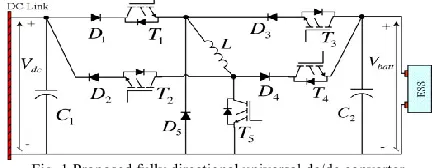
Fig. 1 Proposed fully directional universal dc/dc converter
conversion unit (wind turbines & PV panels) by the primary source. These systems cannot serve as a standalone system for power supply because of these large fluctuations and therefore these systems are always backed up and supported by the auxiliary sources which are rechargeable such as battery units or super capacitors. This sources supplement the main system at the time of energy deficit to provide the power at regulated level and gets recharged through main system at the time of surplus power generation or at their lower threshold level of discharge. Therefore a bidirectional DC DC converter is needed to be able to allow power flow in both the directions at the regulated level.Likewise in HEVs, bidirectional DC DC converters are employed to link up the high voltage DC bus to the hybrid electrical storage system (usually a combination of the battery or a fuel cell with the super capacitor). Here they are needed to regulate the power supply to the motor drive to assist the ICE according to the traction power demanded.
II.SYSTEM DESCRIPTION AND OPERATING MODES
The circuit schematic of the proposed converter is depicted in Fig. 1. The converter has five power switches (T1-5)with internal diodes and five power diodes (D1–D5), which are going to be properly combined to select buck and boost modes of operation. Here, Vdcrepresents the motor drive nominal input voltage during driving mode or the rectified ac voltage at the output of the grid interface converter during plug-in mode (also the input voltage of the grid interface converter to be inverted toac). The nominal voltage of the vehicle’s ESS is represented byVbatt. The proposed converter is capable of operating from VdctoVbattboosting, Vdcto Vbattbucking, and VbatttoVdcboosting, orVbattto Vdcbucking, all with positive output voltage.
In any of the four modes, only one of the power switches is operated in pulse width modulation (PWM) mode, while all the other switches are completely ON or OFF. Therefore, the switching losses are not more than that of any conventional buck or boost converter. In addition, the proposed converter requires only one high-current inductor unlike some of the existing buck and boost converter combinations or the cascaded configurations. Conventional buck–boost converters can step-up or step-down the input voltage. However, they are not capable of providing bidirectional power flow. Moreover, their output voltageis negative with
respect to the input voltage, which needs an inverting transformer to make the output voltage positive. The non-inverted operation capability of the proposed converter totally eliminates the need for an inverting transformer, which reduces the overall size and cost. Although there are some non-inverted topologies, some of them require two or more switches being operated in PWM mode that causes higher total switching losses. The conventional two-quadrant bidirectional converters would operate buck mode in one direction and boost mode in the other direction; however, they cannot operate vice versa. They would not step-up the voltage in the direction that they can step-down.
Two cascaded two-quadrant bidirectional converters may achieve bidirectional power flow with bucking or boosting capabilities; however, they require more than one high-current inductor. In although two switches and two inductors are used, only unidirectional bucking or boosting can be achieved. In the case of a dual-active bridge dc/dc converter, all switches are operated in PWM mode; therefore, switching losses are four times higher in the half-bridge case or eight times higher in full half-bridge case than that of the proposed converter. Dual-active bridge dc/dc converters also require a transformer at the middle stage which would increase the overall losses, size, and cost . Two inductors are required in addition to the transformer, and the number of inductors is three. The, bidirectional power flow is possible with ten switches and two inductors. Although soft switching strategies can be considered for dual-active bridge dc/dc converters in order to reduce the switching losses such as in there should be eight power switches and eight power diodes with three inductors; therefore, a high number of components would not be economical. Moreover, having more than one switch operating in PWM mode would make the control system more complicated.
with add-on batteries regardless of the voltage ratings of the motor drive, battery, and the grid interface converter.
Table-1: OPERATION MODES OF THE PROPOSED CONVERTER
Case 1: Vdc<Vbatt
If the rated dc link voltage is less than battery’s rated voltage, the dc link voltage should be stepped-up during charging in grid connected mode and in regenerative braking during driving. Under the same voltage condition, the battery voltage should be stepped-down during plug-in discharging in grid-connected mode, and in acceleration or cruising during driving.
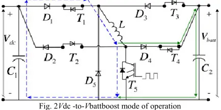
Mode 1) Vdc→ VbattBoost Mode for Plug-in Charging
and Regenerative Braking: In this mode, T1 and T4
are keptON, while T2 and T3 remain in the OFF state,
as shown in Fig. 2. The PWM switching signals are applied to switch T5. Therefore, from Vdcto Vbatt, a
boost converter is formed by D1, T1, L, T5,D4 , and T4
. SinceD1 andD4 are forward-biased, they conduct;
whereasD3 andD2 do not conduct. Since T5 is in PWM
switching mode, when it is turned ON, the current from Vdcflows throughD1, T1, L, and T5 while
energizing the inductor. When T5 is OFF, both the
source and the inductor currents flow to the battery side through D4 and T4
Fig. 2Vdc -to-Vbattboost mode of operation
During this mode, Vdcand Vbattsequentially become
the input and output voltages Since the inductor
current is a state variable of this converter, it is controllable. Therefore, the charging power delivered to the battery in plug-in mode or high-voltage bus current in regenerative braking can be controlled.
Mode 2) Vbatt→ VdcBuck Mode for Plug-in
Discharging and Acceleration: The circuit schematic of this operation modeis provided in Fig. 3. In this mode, T1, T4, and T5 remain OFF,whileT2 is kept in
ON state all the time. The PWM switchingsignals are applied to switch T3. Therefore, from Vbattto Vdc,
abuck converter is formed by T3, D3, D5, L, T2, and
D2. When T3 is turned ON, the current from the
battery passes throughT3, D3, L, T2, and D2 , while
energizing the inductor. When T3 is OFF, the output
current is freewheeled through the D5, T2, and D2 ,
decreasing the average current transferred to the load side. D3 and D2 are forward-biased, whereas D1 and
D4 do not conduct. D5 only conducts when T3 is OFF.
In this mode, Vbattand Vdcare the input and output
voltages, respectively. During stepping-down the battery voltage while delivering power from battery to the dc link, the inductor is at the output and its current is a state variable. Therefore, the dc link voltage and the current delivered to the dc link can be controlled in driving mode.
Fig.3Vbatt -to-Vdcbuck mode of operation
Case 2: Vdc>Vbatt
If the rated dc link voltage is more than the battery’s rated voltage, dc link voltage should be stepped-down during charging in grid-connected mode and in regenerative braking while the vehicle is being driven. Under the same voltage condition, the battery voltage should be stepped-up during plug-in discharging in grid-connected mode and in acceleration or cruising while driving.
Mode 3) Vdc→ VbattBuck Mode for Plug-in Charging
and Regenerative Braking: In this mode, T1 is in the
PWM switchingmode. Switches T2, T3, and T5 remain
in OFF state whileT4 is kept ON all the time.
up by D1, T1, D5, L, D4, and T4 as shownin Fig. 4.
When T1 is turned ON, the current from
VdcpassesthroughD1, T1, L, D4, and T4 while
energizing the inductor.WhenT1 is OFF, the output
current is recovered by freewheelingdiodeD5
decreasing the average current transferred fromdc link to the battery. Since diodes D1 and D4 are
forwardbiased,they conduct whereas D2 and D3 do not
conduct. D5only conducts when T1 is OFF. In this
mode, Vdcand Vbattare the input and output
voltages,respectively. The dc link voltage can be regulated in drivingmode (regenerative braking) by controlling the current transferredto the battery. In plug-in charging mode, the current orpower delivered to the battery is also controllable.
. Fig. 4Vdc -to-Vbattbuck mode of operation
Mode 4) Vbatt→ VdcBoost Mode for Plug-in
Dischargingand Acceleration: During this mode, T1
and T4 remain OFF,whereasT2 and T3 remainONall
the time. Switch T5 is operatedin PWM switching
mode. Therefore, from Vbattto Vdc, a boostconverter is
formed by T3, D3, L, T5, T2, and D2, as illustratedin
Fig. 5.When T5 is turned ON, the current from
Vbattpasses throughT3, D3, L, and T5 while energizing
the inductor. When T5 is OFF, both inductor and the
source currents pass through T2 and D2 to the dc link.
In this mode, D3 and D2 are forward-biasedand they
conduct, whereas D1,D4 , and D5 are reverse-based
and do not conduct. In this mode, Vbattand Vdcare
sequentially the input and output voltages. The dc link voltage can be regulated in driving mode (regenerative braking) by controlling the current drawn from the battery. In plug-in charging mode, the current or power drawn from battery is also controllable.
Fig.5Vbatt -to-Vdcboost mode of operation
III.SWITCHED RELUCTANCE MOTOR
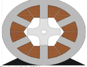
In Switched Reluctance Motor the torque is developed because of the tendency of the magnetic circuit to adopt the configuration of minimum reluctance i.e. the rotor moves in line with the stator pole thus maximizing the inductance of the excited coil. The magnetic behavior of SRM is highly nonlinear. But by assuming an idealistic linear magnetic model, the behavior pattern of the SRM can be adjusted with ease of without serious loss of integrity from the actual behavior pattern. The physical appearance of a Switched Reluctance motor is similar to that of other rotating motors (AC and DC) Induction Motor, DC motor etc. The switched reluctance motor (SRM) is a type of reluctance motor,an electric motor that runs by reluctance torque.
Operating principle: The SRM has wound field coils as in a DC motor for the stator windings.The rotor however has no magnets or coils attached. The rotor of the motor becomes aligned as soon as the opposite poles of the stator become energized. In order to achieve a full rotation of the motor, the windings must be energized in the correct sequence. For example, if the poles a1 and a2 are energized then the rotor will align itself with these poles. Once this has occurred it is possible for the stator poles to be de-energized before the stator poles of b1 and b2 are energized. The rotor is now positioned at the stator poles b. This sequence continues through c before arriving back at the start. This sequence can also be reversed to achieve motion in the opposite direction. This sequence can be found to be unstable while in operation.
Fig 6: 6/4 Pole SRM
For the control system of the proposed topology, an all electric range focused operating strategy has been considered. All operation modes of the proposed converter are combinations of buck and boost operations with different configurations and input/output voltages, as expressed in Table I. Therefore, simplified state-space averaged large-signal transfer functions of the buck or boost modes of operations can be derived. The state space block diagrams for the boost and buck modes of operations of the proposed converter are shown in Figs. 7 and 8.
Fig.7State-space model of the simplified converter in boost mode
Fig.8 State-space model of the simplified converter in buck mode
Two different controllers are incorporated for the proposed system: one employed in plug-in charging/discharging and the other is for acceleration/deceleration during driving. In plug-in mode, generally, it is desired to control the charging or discharging power of the battery, whereas in driving mode it is important to provide a regulated dc link voltage to the motor drive. Therefore, a power controller is used for plug-in modes and a double-loop voltage and current controller is employed for acceleration/braking modes of the driving.
Fig.9 DC/DC converter charge/discharge power controller
The battery power controller, shown in Fig. 9, allows the reference charge or discharge power to/from the battery to be tracked This reference power can be determined based on the SoC of the battery, user requirements, and the state of the grid. The cascaded voltage and current controller, shown in Fig. 10, allows the high-voltage bus to be kept at the proper voltage while also accommodating the power demanded or supplied by the dc link. This enables regenerative recharging of the battery from the dc link and discharging of the battery to the dc link, while maintaining the proper dc link voltage level for the hybrid vehicle.
V. MATLAB/SIMULINK RESULTS
Here the simulation is carried by different conditions as shown in bellow and finally proposed converter with SRM drive performance also verified
Fig.10 Matlab/simulink model of Vdc→ VbattBoost mode
Fig.11 simulation results for Vdc, V battery, switching pulses and
Fig.12 Matlab/simulink model of Vbatt→ VdcBuckmode
Fig.13 simulation results for ofbuck mode
Fig.14 Matlab/simulink model of Vbatt→ VdcBoost mode
Fig.15 simulation results of boost mode
Fig.16 simulation results for PV CELLofbuck mode
Fig.17 Matlab/simulink model of proposed converter with SRM drive
Fig.19 shows the output waveforms of armature current. Torque and speed of the SRM drive
VI. CONCLUSION
In this paper a new SRM drive is introduced with proposed converter. The proposed converter for SRM is analyzed and its operating modes are discussed. The proposed converter uses one switch for each motor phase. In this concept a novel dc/dc converter structure that is suitable for both industrial needs and the retrofit electric vehicle conversion approaches for all EV, HEV, and PHEVs regardless of their rated dc link voltage and motor drive inverter voltage as well as the battery nominal voltage. The proposed topology is suitable not only for conversion approaches but also is a good candidate to reduce the number of dc/dc converters from two to one in commercially available. Finally in this concept proposed converter applied switched reluctance motor drive applications and verified the speed and torque characteristics of the SRM.
VI.REFERENCES
[1] A. Emadi, Y. L. Lee, and R. Rajashekara, “Power electronics and motor drives in electric, hybrid electric, and plug-in hybrid electric vehicles,” IEEE Trans. Ind. Electron., vol. 55, no. 6, pp. 2237–2245, Jun. 2008.
[2] R. Ghorbani, E. Bibeau, and S. Filizadeh, “On conversion of electric vehicles to plug-in,” IEEE Trans. Veh. Technol., vol. 59, no. 4, pp. 2016–2020, May 2010.
[3] F. H. Khan, L. M. Tolbert, and W. E. Webb, “Bi-directional power management and fault tolerant feature in a 5-kW multilevel dc-dc converter with modular architecture,” IET Power Electron., vol. 2, no. 5, pp. 595– 604, 2009.
[4] G. Zorpette, “The smart hybrid,” IEEE Spectrum, vol. 41, no. 1, pp. 44–47, Jan. 2004.
[5] Energy Independence and Security Act of 2007 (CLEAN Energy Act of 2007), One Hundred Tenth Congress of the United States of America, At the First Session, Washington DC Jan. 2007. [6] Z. Amjadi and S. S. Williamson, “Power-electronics-based solutions for plug-in hybrid electric vehicle energy storage and management systems,” IEEE Trans. Ind. Electron., vol. 57, no. 2, pp. 608–616, Feb. 2010.
[7] S. Han and D. Divan, “Bi-directional DC/DC converters for plug-in hybrid electric vehicle (PHEV) applications,” in Proc. 23rd Annu. IEEE ApplPower Electron. Conf. Expo., Austin, TX, Feb. 2008, pp. 787–789.
[8] D. C. Erb,O.C.Onar, andA.Khaligh, “Bi-directional charging topologies for plug-in hybrid electric vehicles,” in Proc. 25th Annu. IEEE Appl. PowerElectron. Conf. Expo., Palm Springs, CA, Feb. 2010, pp. 2066–2072.
[9] S. S. Raghavan, O. C. Onar, and A. Khaligh, “Power electronic interfaces for future plug-in transportation systems,” IEEE Power Electron. Soc.Newslett., vol. 24, no. 3, pp. 23–26, Third Quarter 2010.