PV Based Single Phase Reverse Voltage
Multilevel Inverter
Kamlesh Kumari1, Ajay Kumar2
PG Student [PED], Dept. of EE, Baddi University of Emerging Science & Technology, Baddi, India1 Assistant Professor, Dept. of EE, Baddi University of Emerging Science & Technology, Baddi, India2
ABSTRACT: Multilevel inverters are used in high power and high voltage applications. There performance is finer to that of conventional two level inverter due to reduced harmonic distortion. This paper present a topology of multilevel inverter called reverse voltage multilevel inverter which is used with the solar panel. Selective harmonic elimination (SHE) technique is used for its modulation. Reverse voltage multilevel inverter needed less number of power electronics component, and less gate drive circuit. Due to all these factors its overall cost is low and it is less complex. A seven level reverse voltage MLI is simulated in Matlab and there simulation results are shown in the paper.
KEYWORDS: Multilevel inverter, inverter, power.
I.INTRODUCTION
Multilevel power conversion was first introduced more than two decades ago. The general concept involves utilizing a higher number of active semiconductor switches to perform the power conversion in small voltage steps. There are several advantages of MLI when compared with the conventional inverter. The smaller voltage steps lead to the production of higher power quality waveforms and also reduce voltage (dv/dt) stress on the load and the electromagnetic compatibility concerns[1]. Another important feature of multilevel converters is that the semiconductors are wired in a series-type connection, which allows operation at higher voltages. However, the series connection is typically made with clamping diodes, which eliminates overvoltage concerns [2]. The multilevel voltage source inverters’ unique structure allows them to reach high voltages with low harmonics without the use of transformers or series-connected synchronized switching devices. The general function of the multilevel inverter is to synthesize a desired voltage from several levels of dc voltages. For this reason, multilevel inverters can easily provide the high power required of a large electric drive.
As the number of levels increases, the synthesized output waveform has more steps, which produces a staircase wave that approaches a desired waveform [3]. The voltage balancing can be addressed by using redundant switching states, which exist due to the high number of semiconductor devices. However, for a complete solution to the voltage-balancing problem, another multilevel converter may be required [4]. Some applications for these new converters include industrial drives [5], flexible ac transmission systems (FACTS) [6]–[8], and vehicle propulsion [9], [10]. One area where multilevel converters are particularly suitable is that of renewable photovoltaic energy that efficiency and power quality are of great concerns [11] In [12] and [13], the multilevel output is generated with a multi winding transformer. However, the design and manufacturing of a multi winding transformer are difficult and costly for high-power applications.
II.MULTILEVEL INVERTER USING REVERSE VOLTAGE TOPOLOGY
Fig. 1 Block diagram of Reverse Voltage Multilevel Inverter
The Reverse Voltage topology in seven levels is shown in Fig. 2. As it can be seen, it requires ten switches and three isolated sources.
Fig. 2 Single phase Seven-level Reverse voltage Multilevel Inverter
III.SELECTIVE HARMONIC ELEMINATION
series analysis, the amplitude of any odd nth harmonic of the stepped waveform can be expressed as (1), whereas the amplitudes of all even harmonics are zero.
h = 4
nπ V cos(nαk) (1)
Where is the level of dc voltage, n is an odd harmonic order, m is the number of switching angles, is the switching angle. According to Fig.3 α 1 to must satisfy the condition α <α ………α <π2. According
to (1), to keep the number of eliminated harmonics at a constant level, all switching angles must be less than π 2 .
Fig. 3 Stepped voltage waveform
The third harmonics and its multiple are usually not eliminated by using SHE. Since they are naturally eliminated by three phase load[14].
IV.BOOST CONVERTER
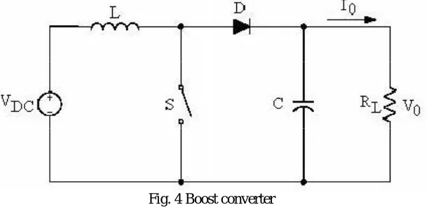
Boost converter is an important element in pv system. Boost converter give output voltage greater than the input voltage. Fig.4 shows the circuit diagram of boost converter. It is a class of switch mode power supply containing at least two semiconductor switches and at least one storage element such as capacitor, inductor.
Fig. 4 Boost converter
V.SOLAR PHOTOVOLTIC CELL
Solar photovoltaic (PV) electrification is an important renewable energy source. The electric which is converted directly from solar irradiation via PV panel is not steady due to different solar intensity. To maximize the PV panel output power, perturb and observe (P&O) maximum power point tracking (MPPT) has been implemented into the PV system. Through a buck-boost DC-DC converter, MPPT is able to vary the PV operating voltage and search for the maximum power that the PV panel can produce [14].
Fig. 4 P & O based MPPT Solar PV System
VI.RESULT AND DISCUSSION
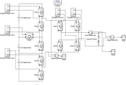
The Fig. 6 shows the simulink model of seven level reverse voltage multilevel inverter. Three separate dc voltage source are used and IGBT are used as a switch. For seven level reverse voltage multilevel inverter ten switches are used. Six switches are used for the level generation and h-bride for polarity generation.
Fig
. 6 Single Phase Reverse Voltage MLIBoost converter is used to step up the output voltage. Some time we does not get the desired output voltage from the pv system so to boost the output voltage of pv system we used the boost converter.Fig.7(a) shows the boost converter and fig.7(b) shows the output voltage of boost converter.
Fig. 7(b) Output voltage of Boost Converter
The fig. 8(a) shows that the pv system is connected with the boost converter. The output of solar pv module is given to the boost converter. This output is used as an input source of boost converter. Fig.8(b) shows the power voltage characteristics and fig. 8(c) shows the voltage current characteristics.
Fig. 8(b) Power voltage curve
Fig. 8(c) Current Voltage curve
VII.CONCLUSION
The main purpose of this thesis was to analyse the PV based reverse voltage multilevel inverter. A Matlab/Simulink Model with PV array, boost converter & Reverse Voltage 7-level Inverter is simulated. Output waveform is analysed & Maximum power point is tracked using Perturb and observation (P & O) method.
REFERENCES
[1] K. Jang-Hwan, S.-K. Sul, and P. N. Enjeti, “A carrier-based PWM method with optimal switching sequence for a multilevel four-leg voltage source inverter,” IEEE Trans. Ind. Appl., vol. 44, no. 4, pp. 1239–1248, Jul./Aug. 2008.
[2] Ehsan Najafi, Halim Mohamed Yatim, “ Design and Implementation of a New Multilevel Inverter Topology” IEEE Trans. on industrial electronics, vol. 59, no. 11, november 2012.
[3] L. M. Tolbert, F. Z. Peng, and T. G. Habetler, “Multilevel converters for large electric drives” IEEE Trans. Ind. Appl., vol. 35, pp. 36–44, Jan./Feb. 1999.
[4] R. H. Osman, “A medium-voltage drive utilizing series-cell multilevel topology for outstanding power quality,” in Conf. Rec. 34th IEEE IAS Annu. Meeting,vol. 4, pp. 2662–2669.1999.
[5] E. Najafi and A. H. M. Yatim, “A novel current mode controller for a static compensator utilizing Goertzel algorithm to mitigate voltage sags,” Energy Convers. Manage., vol. 52, no. 4, pp. 1999–2008, Apr. 2011.
[6] N. Seki and H. Uchino, “Converter configurations and switching frequency for a GTO reactive power compensator,” IEEE Trans. Ind. Appl., vol. 33, no. 4, pp. 1011–1018, Jul./Aug. 1997.
[7] G. Shahgholiyan, E. Haghjou, and S. Abazari, “Improving the mitigation of voltage flicker by usage of fuzzy control in a distribution static synchronous compensator (DSTATCOM),” Majlesi J. Elect. Eng., vol. 3, no. 2, pp. 25–35, Jun. 2009.
[8] K. Nakata, K. Nakamura, S. Ito, and K. Jinbo, “A three-level traction inverter with IGBTs for EMU,” in Conf. Rec. IEEE IAS Annu. Meeting,, vol. 1, pp. 667–672.1994.
[9] A. Jidin, N. R. N. Idris, A. H. M. Yatim, T. Sutikno, and M. E. Elbuluk, “An optimized switching strategy for quick dynamic torque control in DTC-hysteresis-based induction machines,” IEEE Trans. Ind. Electron., vol. 58, no. 8, pp. 3391–3400, Aug. 2011.
[10] K. Y. Lau, M. F. M. Yousof, S. N. M. Arshad, M. Anwari, and A. H. M. Yatim, “Performance analysis of hybrid photovoltaic/diesel energy system under Malaysian conditions,” J. Energy, vol. 35, no. 8, pp. 3245–3255, Aug. 2010.
[11] R. Teodorescu, F. Blaabjerg, J. K. Pedersen, E. Cengelci, and P. N. Enjeti, “Multilevel inverter by cascading industrial VSI,” IEEE Trans. Ind. Electron., vol. 49, no. 4, pp. 832–838, Aug. 2002.
[12] D. A. B. Zambra, C. Rech, and J. R. Pinheiro, “A comparative analysis between the symmetric and the hybrid asymmetric nine-level series connected H-bridge cells inverter,” in Proc. Eur. Conf. Power Electron. Appl., pp. 1–10.2007.
[13] J. Holtz, “Pulsewidth modulation for power converters” Proc. IEEE, vol. 82, pp. 1194–1214, Aug. 1994.
[14] C. S. Chin, P. Neelakantan, H. P. Yoong, K. T. K. Teo, “Optimisation of fuzzy based maximum power point tracking in PV system for rapidly Changing solar irradiance” Transaction on Solar Energy and Planning ISSN: 2229-8711 Online Publication, June 2011.
[15] Jose Rodriguez, leopoldo G. Franquelo, “Multilevel converter: An Enabling Technology for High-Power Applications” Proceedings of the IEEE. Vol. 97, No. 11, November 2009.
[16] A. Chouder, F. Guijoan, and S. Silvestre, “Simulation of fuzzy based tracker and performance comparison with perturb and observe method”, Renouvelables, Vol.11, pp. 577.2008.
[17] Roberto Faranda, and Sonia Leva, “Energy comparison of MPPT techniques for PV systems”, WSEA transactions on Power Systems, pp. 446.2008.