ISSN 2286-4822 www.euacademic.org
Impact Factor: 3.1 (UIF) DRJI Value: 5.9 (B+)
Removing Spatial Redundancy from Image by Using
Variable Vertex Chain Code
TAWFIQ A. AL-ASADI
College of Information Technology Babylon University Iraq
FANAR ALI JODA
College of Information Technology Babylon University Iraq
Abstract:
In this paper we have proposed an efficient lossless image compression method, this method consists of two parts, the first is compressed part that based on two approaches of chain code representation the first approach is variable vertex chain code (V_VCC) is used to encode boundary of segment to remove spatial redundancy in image, the second approach is Freeman chain code 8-directional (FCCE) is used to encode remaining values then the values that belong to two approaches of chain code will be removed from image and reduce the size of image then begins a new level and will apply the same steps as the previous, the second is decompressed part , depending on variable vertex chain code set, Freeman chain code set, start points and values decompressed part will rebuild the original image identically.
Key words: Chain code, Lossless image compression, FCCE, Segmentation, V_VCC.
1. Introduction
ranging from consumer digital photo albums to remote earth sensing. The growing production of images and demands to their quality require high performance compression systems for efficient transmission, storage and archival (Krivoulets 2004).
Various types of redundancy exist in images, such as temporal redundancy, spatial redundancy (or interpixel redundancy), coding redundancy, spectral redundancy and psychovisual redundancy. The main goal of image compression is to minimize the number of bits required to represent the original images by reducing the redundancy in images, the essential issue in image compression is to design efficient and effective compression schemes (Zha 2007).
In terms of decompression ability, image compression systems can be generally classified into two main types: lossless image compression and lossy image compression.
Lossy compression involves some loss of information. Data that have been compressed using lossy techniques cannot be fully reconstructed. In return for accepting this loss, a higher compression ratio can be gained in comparison to lossless techniques. Generally, the applications of lossy compression are limited to the media domain (i.e., images, videos and audio (Kattan 2010).
If data have been lossless compressed, the original data can be reconstructed exactly from the compressed data. It is generally used for applications that cannot tolerate any difference between the original and reconstructed data (Panrong 2001)
Regardless of the compression type, all algorithms share a similar process when compressing information, namely: modelling and coding
systems are often different for lossless and lossy methods. Selecting the suitable modeling method is important because the more regularity we find the more we can reduce the sequence length. In particular, we cannot reduce the sequence length at all if we do not know what is redundant in it.
The second stage, coding, is based on the knowledge obtained in the modeling stage, and removes the redundant data, the coding systems are not so diverse because the modeling process is the stage where the adaptation to the data is made, therefore we only have to encode the sequence efficiently removing known redundancy (Deorowicz 2003).
Image compression can be achieved by coding domain methods, spatial domain methods, transform domain methods or a combination of these methods. Coding methods are directly applied to the raw images handling them as a sequence of discrete numbers, common coding methods include: Arithmetic, Huffman, Lempel-Ziv Welch (LZW), and Run-Length.
Spatial domain methods, which are a combination of spatial domain algorithms and coding methods, not only run directly on the gray values in an image but also try to remove the spatial redundancy, In transform domain compression; the image is represented using an suitable basis set, and the goal is to obtain a sparse coefficient matrix, Discrete Cosine transform (DCT) based compression and wavelet transform are two examples of transform domain methods. Recently, there has been a growing interest in reversible/lossless image compression of medical images (Vernuri et al. 2007).
2. Chain codes
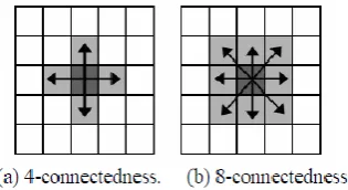
Figure (1). Digital images usually are acquired and processed in a grid format with equal spacing in the x - and y-directions, so a chain code could be created by following a boundary in, say, a clockwise direction and assigning a direction to the segments connecting every pair of pixels. This method generally is unacceptable for two principal reasons: (1) The resulting chain of codes tends to be quite long, and (2) any small disturbances along the boundary due to noise or imperfect segmentation cause changes in the code that may not be related to the shape of the boundary (Gonzalez & R. E. Woods, 2002).
Figure (1) Different definitions of pixel neighborhoods
There are several types have been developed based on Freeman chain Code, briefly we'll show below the main types of chain code:
i. Original Vertex Chain Code (VCC): In 1999, E. Bribiesca
first introduced the original vertex chain code (VCC). The VCC is based on the numbers of cell vertices which are in touch with the bounding contour of the shape. This code determines the number of pixels of the binary shape that are in touch with the observed vertex of the shape’s boundary contour.
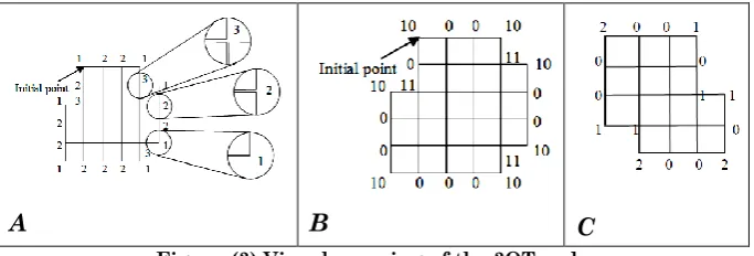
Figure (3 A) is an illustration of VCC which presents a shape. It is previous that there are only three numbers of 0, 1, and 2 which are needed to present a boundary composed with pixels of quadrate grids (Li et al. 2012).
ii. Variable-Length Vertex Chain Code (V_VCC) The
variable-length vertex chain code (V_VCC). This chain code also uses rectangular cells code of VCC. It has three elements 1, 2, and 3. These elements are represented by binary digits (0, 10, and 11). Variable-length VCC (V_VCC) code is well-defined by the probability of three code occurring. The experiment presented that the probability of code 2 is greater than the other two. Therefore, at V__VCC the binary digit 0 is used to represent code 2, 10 for code 1, and 11 for code 3 by applying the concept of Huffman coding, As depicted in figure (3 B) (Wulandhari and Haron 2008).
iii. OrThogonal chain code (3ot) the 3OT is based on the
three relative changes of orthogonal directions given by Figure (3 C). In the 3OT, there are three elements: 0, 1 and 2. The element “0” represents no direction change which means to “go straight” through the contiguous straight line segments following the direction of the last segment; the “1” indicates a direction change forward with regard to the basis segment; and “2” means to “go back” with regard to the direction of the basis segment (Sanchez-Cruz 2010).
Figure (2) Visual meaning of the 3OT code
Figure (3) Visual meaning of the 3OT code
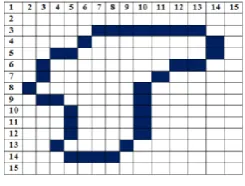
We will take an example then compare the methods (FCCE, 3OT, VCC, V_VCC) of chain code to select the best in term of efficiency of compression ratio which use it to encode boundaries, which produces from the segmentation process in proposed system.
Figure (4) shape
The result of encoding the shape in figure (4) is illustrated in table (1).
Method encoding Number of
symbols
Numbers of bits FCCE 0,0,0,0,0,0,7,6,5,4,5,5,6,6,6,6,5,5,4,4,4,3,1,2,2,3
,4,3,1,6,1,0,1,1 34 102
3OT 1,0,0,0,0,0,0,2,1,1,0,2,1,1,0,1,1,1,0,0,0,0,1,1,1,1 ,1,0,0,0,2,1,1,2,1,0,0,1,0,1,1,1,2,1,0,1,1,1,0,1,1, 1
52 104
VCC 1,2,2,2,2,2,2,1,3,1,2,1,3,1,2,3,1,3,2,2,2,2,1,3,1,3 ,1,2,2,2,1,3,1,1,3,2,2,3,2,1,3,1,1,3,2,1,3,1,2,3,1, 3
52 104
V_VCC 10,0,0,0,0,0,0,10,11,10,0,10,11,10,0,11,10,11,0, 0,0,0,10,11,10,11,10,0,0,0,10,11,10,10,11,0,0,1 1,0,10,11,10,10,11,0,10,11,10,0,11,10,11
52 84
Table (1) encoding by using chain code methods
4. The proposed system
The proposed system is lossless image compression, mainly based on two approaches of chain code representation to increase efficiency of algorithm, according to the comparison in Table1; the approach of V_VCC is considered the best in terms of compression ratio, which is used to encode boundaries of the segments, the goal from segmentation is to remove the spatial
redundancy from images.
The second type FCCE is used to encode values that do not form a segment the reason of using FCCE is the ease and flexibility to encode the values in any form if they were connected.
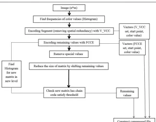
The proposed system consists of two parts, (Compressed
and Decompressed), as depicted in figure (7)
The first part consists of four steps:
The first step: finding frequencies of values and put them in a
vector then arrange them in descending order, the aim of this step is to increase the efficiency of the algorithm in terms of time and compression ratio, the algorithm starts with value that has highest frequency and ignores the values of the frequencies which does not meet the threshold condition, this step represents the modeling.
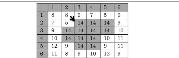
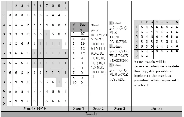
The second step: removing spatial redundancy by
1 2 3 4 5 6 1 8 8 9 7 5 9 2 7 5 14 14 14 9 3 9 14 14 14 14 10 4 10 14 14 14 10 11 5 12 9 14 14 9 11 6 11 8 9 10 12 9
Figure (5) an example to illustrate detection the boundary of segment
The value of location (2, 3) is 14; it has four adjacent values equal to 14, as follows:
1. Location (2,4) has five adjacent values equal to 14 2. Location (3,4) has eight adjacent values equal to 14 3. Location (3,3) has seven adjacent values equal to 14 4. Location (3,2) has four adjacent values equal to 14
So, the algorithm will add the location (2,3) to the vectorbndr and moving to the location (3,2) (has fewest number of adjacent values equal to 14) , which is the center of a new mask and perform the same previous procedure and continue until return to the start point.
In this case we have a closed form, now checking the similarity of the internal values after verification from the similarity of internal values, the boundary is encoded based on the values stored in the vectorbndr using V_VCC and adding (V_VCC set, start point, color value) to the compressed file then replacing the boundary and internal of the value VL with special value (SV) to become highlighted value.
Then look for another segment of the same color value, and so on, after completing of value VL the algorithm, will select another value which has less frequency and perform same previous procedure.
The thirdstep / remained values that do not form a segment is
encoded by using the second approach of chain code (FCCE) for more details, see Ref. (Tawfiq and Fanar 2014).
The fourthstep / removing special values from original matrix
values were spaced that could be encoded it to increase the compression ratio, the new matrix after shrinking process represents a new level, that could be applied the steps (first, third and fourth only) for new level.
The algorithm will be stopped when access to the matrix does not have any context for color value can be encoded.
After processing the last level the remained values will be added to the compressed file, the example in figure (6) shows the proposed system for compressed part.
The second part / in this part is to rebuild the original image
that consider as reverse process compared to compressed part. In the first step generating matrix contain remained values that belong to last level in compressed part.
In the second step the values are returned to their original positions depending on the V_VCC, FCCE sets which are considered as indicators to the positions of values, at the end when accessing to the first level will get on the original image without loss.
Figure (7) Block diagram (encoding part)
5. Algorithm and experimental results
5.1 Compressed Algorithm:
Input : Image file (8 bpp – 256 colors)
Output : Text file Begin
Level=1
Find frequencies for color values (Histogram) Sort the vector of histogram (descending order) Index = 0
Repeat
VL= histogram (index)
Determine boundary of segment for VL Check boundary of segment
If checkb=true then Begin
If checki=true then Begin
Encoding boundary of segment with V_VCC
Replace (boundary and internal values) with special value (-1)
Add (V_VCC set, start point and VL) to compressed file
End; End;
Index = index +1 Until (index = n) Repeat
Find histogram Index=0
Repeat
VL=histogram (index) Select start point for VL Obtain (FCCE) for VL
If (FCCE (VL)) satisfy threshold then Begin
Add (FCCE set, start point and VL) to compressed file Replace location of VL witch correspond to FCCE set with special value (-1)
End;
Index = index +1 Until (index = n)
Remove special value from matrix
Shift remaining values (the size of matrix will be reduce) Until matrix has not chain code satisfy threshold condition End.
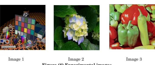
5.2 Experimental Results
Image 1 Image 2 Image 3 Figure (8) Experimental images
After proposed system is applied on the images above with size of 512*512 we get the following results as depicted in Table (2).
Image Bytes of image Bit rate (bpp)
Image 1 262144 3.24
Image 2 262144 3.57
Image 3 262144 4.03
Table (2) compression results of images size 512*5126.
Conclusions
In this research, we have proposed an efficient lossless image compression based on two types of chain code to increase compression ratio based on the experimental results, we note the following points:
The number of levels have an impact on the required time to compress the image.
It is possible identify a specific number of levels.
The segmentation process will be implemented in the first level only that why it's rare to get a segment in other levels because the process of shifting.
The proposed system can be applied on images (24 bit) by separating the images to 3 matrixes (R, G and B) then compressing each one separately.
values to their original positions in the image depending on V_VCC and FCCE that consider as indicators.
BIBLIOGRAPHY:
Abbas, Tawfiq Abdulkhaleq and Fanar Ali Joda. 2014. “Locational Image Compression based on Chain Code Representation.” IOSR Journal of Engineering 3(1): 24-29.
Deorowicz, Sebastian. 2003. Universal lossless data compression algorithms. Silesian University of Technology.
Gonzalez, R. C. & R. E. Woods. 2002. Digital Image Processing. 2nd ed. www.imageprocessingbook.com.
Kattan, Ahmed. 2010. Evolutionary Synthesis of Lossless Compression Algorithms: the GP-zip Family, Ph.D. dissertation. University of Essex.
Krivoulets, Alexandre. 2004. Design of Efficient Algorithms for Image Compression with Application to Medical Images, Ph.D. dissertation. IT University of Copenhagen.
Li, Linghua, Yining Liu, Yongkui Liu, and Borut Žalik. 2012. "Evaluation and Comparison on the Techniques of Vertex Chain Codes." Journal of Software 7(12).
Panrong, X. 2001. Image Compression by Wavelet Transform. Master Thesis, East Tennessee State University.
Sanchez-Cruz, Hermilo. 2010. Proposing a new code by considering pieces of discrete straight lines in contour shapes. Elsevier.
Vernuri, B. C., S. Sahni, F. Chen, C. Kapoor, C. Leonard and J. Fitzsimmons. 2007. Lossless Image Compression, University of Florida.
Wulandhari, Lili Ayu, and Habibolah Haron. 2008. "The Evolution and Trend of Chain Code Cheme." ICGST-GVIP 8(3).