Available online: https://edupediapublications.org/journals/index.php/IJR/ P a g e | 2267
A Novel DFR Suppression Control for the Single Phase Multi-Input
based Quasi-ZSI
Gattupally Sindhuja & D. Prasada Rao
1M. Tech Student Department of PE ELLENKI College of E&T
2Associate professor Department of EEE ELLENKI College of E&T
Abstract
Mismatched double-frequency power
is existed between the dc input and ac output In single-phase photo voltaic (PV) system. In a passive network the double-frequency ripple (DFR) energy needs to be buffered. Otherwise, the ripple energy will flow into the input side and adversely affect the PV energy gather. In existed PV system, electrolytic capacitors are usually used for high capacitance. However, electrolytic capacitors are considered to be one of the most failure prone components in a PV inverter. In proposed system, a capacitance reduction control strategy is proposed to buffer the DFR energy in single-phase Z-source/quasi-Z-source inverter applications. The capacitance requirement can reduced and achieve low input voltage DFR in a proposed control method. Consequently, highly good in quality film capacitors can be used. The increased with-out using any extra hardware components. Switching device voltage stress and power loss due to the proposed control strategy will also be discussed.
Simulation and experimental results are also shown to verify the proposed circuit and analysis.
I. INTRODUCTION
Today’s world putting more efforts into distributed power generation (DG) of renewable energy sources (RES), such as photovoltaic (PV), wind power and fuel cells, which are sustainable and environmental friendly. Practically, several DGs consists distributed power grid and further they can be constructed through micro-grid with local loads and managements. To ensure proper performance of the micro-grid, DG is usually required to work in stand-alone or grid-connected.
single-Available online: https://edupediapublications.org/journals/index.php/IJR/ P a g e | 2268
stage buck–boost and improved reliability. Z-source inverter (ZSI) is known as a single-stage buck/boost inverter. With an impedance network coupling. In three-phase and single-phase the proposed scheme enables PV string voltage boost to a higher level, and solves the imbalance of DC-link voltage in traditional CHB inverters. A multilevel voltage waveform of applications ZSI and qZSI are both utilized. For higher voltage application and higher performance, single-phase ZSI/qZSI can also be connected in cascaded structure. Because of its single-stage voltage buck/boost properties, the ZSI can deal with variation in input voltage in a wide range, which is conventionally achieved by a two-stage DC-DC cascaded by DC-DC-AC structure. Advantages and improved reliability due to the allowance of shoot-through state, ZSI gains increasing attention and was presented for use in several applications, such as DG, UPS, fuel cell vehicles, PV or wind power conversion, electronic loads, etc.
Photovoltaic (PV) Module Integrated Converter (MIC), which connects PV panels to single-phase ac grid in a modular structure, has become an important trend in PV market. The research and development of MICs have resulted in inverters ranging from 100 to 300 W. The MIC features several advantages such as low cost
of mass production, easier installation and expansion, and improved energy harvesting due to the individual MPPT. However, compared with the string inverters, MICs have lower efficiencies. Three- phase applications, the Z-source (ZS)/quasi-Z-Z-source (qZS) network needs to be designed to handle the high-frequency ripples. High and low frequency ripples are handled by the single phase pv system. In a single-phase qZSI system the low-frequency
ripple issue studied.
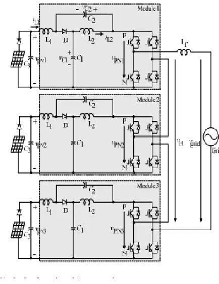
Fig.1.Diagram of a single phase qzsi-based pv system
Available online: https://edupediapublications.org/journals/index.php/IJR/ P a g e | 2269
Ideally, the DC-side output power is pure dc and the ac-side power contains a dc component plus ac ripple component whose frequency is two times the grid voltage frequency. The mismatched ac ripple is called as double-frequency ripple (DFR). DFR power needs to vary by the passive components, to balance the power mismatch between the dc side and ac side.
Mainly the qZS capacitor C1 which has higher
voltage rating than C2. The DFR peak power is
the same as the dc input power, so large capacitance is needed to buffer this ripple energy. To achieve high inverter power density with reasonable cost, electrolytic capacitors are usually selected. Electrolytic capacitors contain a complex liquid chemical called electrolyte to achieve high capacitance and low series resistance. As the electrolytic capacitors age, the volume of liquid present decreases due to evaporation and diffusion. This process is accelerated with higher temperature, eventually leading to performance degradation over time. Therefore, electrolytic capacitors are considered to be the weak component regarding to lifetime, especially under outdoor operation conditions.
A.Quasi-Z Source Inverter:
The qZSI can be operated in two states, i.e., the non-through state and the shoot-through state. Fig. shows the qZSI equivalent
circuits operating in the two states and defines the polarities of all voltages and currents.
Fig 2. Grid Connected System
To calculate the DFR for qZSI accurate analytical model and for selecting the capacitances design guidelines have been developed to limit the DFR .Nevertheless, the required capacitance is still large. To reduce the DFR of dc-link voltage in ZSI two additional
smoothing-power circuits are employed.
Available online: https://edupediapublications.org/journals/index.php/IJR/ P a g e | 2270
However, the method is used for application with constant voltage input source and DFR current is induced in the inductor and the input side. The ripple current will decrease the energy harvest from the PV panels so this is not used in PV application.
In some reported single-phase two-stage system which is composed of a dc–dc converter and H-bridge inverter, the dc-link capacitance can be significantly reduced by using dedicated control.
In this paper, mitigate the input DFR without using large capacitance, a new control strategy is proposed for ZSI/ qZSI to which enables us to use the highly reliable film capacitors. There is no extra hardware needed to implement the capacitance reduction. The proposed control system incorporates a modified modulation strategy and a DFR suppression controller. In order to apply the capacitance reduction method, it is necessary to study the impact of decreasing the capacitance on system design and performance. The gallium nitride (GaN) devices are applied in the inverter to increase the system efficiency at high switching frequency. Finally, experimental results are provided to verify the effectiveness of the proposed control system. Several control strategies been proposed for the cascaded PV
Available online: https://edupediapublications.org/journals/index.php/IJR/ P a g e | 2271
Fig.3 Diagram of the proposed control system
2.PROPOSED CONTROL SYSTEM FOR CAPACITANCE REDUCTION
The basic principle of the proposed capacitance reduction method can be explained
by ½c(v²c_max - v²c_min) (1) Where C is
the capacitance, E is the ripple energy that is
stored in the capacitor, and VCmax and VCmin
are the maximum and minimum voltages across the capacitor. According to (1), there are two
ways to increase E. One is to increase the
capacitance C, and the other way is to increase
the voltage fluctuation across the capacitor. Instead of increasing the capacitance, the proposed control system will increase the voltage fluctuation across the qZS capacitors to buffer more double frequency power strategy is needed to impose the DFR on qZS capacitors while preventing the ripple energy from flowing into the input. In order to achieve this, a modified
modulation strategy and an input DFR suppression controller represented.
Fig.4 Diagram of the proposed control system
3.IMPACT OF CAPACITANCE REDUCTION
A. System Stability
In order to apply the proposed control system, it is necessary to study impact of
decreasing C1 on system stability. The possible
operation states of voltage fed qZSI have been summarized with equivalent circuits, and the averaged model of qZSI can be obtained.
Available online: https://edupediapublications.org/journals/index.php/IJR/ P a g e | 2272
Fig 5. Schematic diagram of proposed control
system
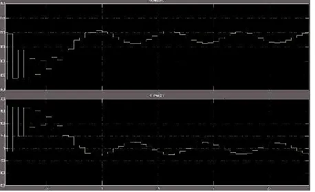
Fig 6. Input voltage waveform of the qZSI
Fig 7. Output Current and voltage waveform of the qZSI
Fig 8. Vc2 Waveforms of the qZSI with proposed
control diagram of proposed control
Fig 9. Vdc Waveforms of the qZSI with proposed
control diagram of proposed control
Fig 10. Vin Waveforms of the qZSI with proposed
control
Fig 11. Output current waveform of the qZSI with
Available online: https://edupediapublications.org/journals/index.php/IJR/ P a g e | 2273
5.CONCLUSION
In this paper, Instead of using large capacitance, to minimize the capacitance requirement in single-phase qZSI PV system a new control strategy is proposed. The qZS capacitors are imposed with higher double-frequency voltages to store the DFR energy. To decouple the input voltage ripple from the qZS capacitor DFR,a modified modulation and an input DFR suppression controller are used, to prevent the ripple energy flowing into the input PV side. The small signal model is developed and shows that the capacitance reduction does not impact the system stability much. For the developed 1-kW quasi-Z-source PV+battery system,2mF capacitor can be replaced with a
200μF capacitor by using the proposed method.
However, the voltage stress across the switching devices was increased by 53%compared with the conventional design. The efficiency was decreased by 0.12%-0.69% at several selected operation points. It is also shown that there is more benefit if the method is applied for 240 Vrms output qZSI. The increase of the switching device voltage stress is only 15% when compared with conventional design. In single phase ZSI application this control strategy can be used.
6.REFERENCES
[1] Y.Li,S.Jiang,J.G.Cintron-
Rivera,andF.Z.Peng,“Modelingandcontrolof
quasi-z-source inverter for distributed
generationapplic
ations,”IEEETrans.Ind.Electron.,vol.60,no.4
,pp.1532–1541,Apr.2013.
[2]
Y.Huang,M.Shen,F.Z.Peng,andJ.Wang,“Z-Sourceinverterforresidentialphotovoltaicsyst
ems,”IEEETrans.PowerElectron.,vol.21,no.
6,pp.1776–1782,Nov.2006.
[3]
D.Cao,S.Jiang,X.Yu,andF.Z.Peng,“Low-
costsemi-Z-sourceinverterforsingle-phasephotovoltaicsystems,”IEEETrans.Pow
erElectron.,vol.26,no.12,pp.3514– 3523,Dec.2011.
[4] Wei,H.Liu,J.ZhangandD.Xu,“Analysisof
powerlossesinZ-sourcePVgrid-connectedinverter,”inProc.IEEE8thInt.Conf.
PowerElectron.ECCEAsia,May30– Jun.3,2011,pp.2588–2592.
[5] T.Chun,H.H.Lee,H.G.Kim,andE.C.Nho,“ PowercontrolforaPVgenerationsystemusinga
Available online: https://edupediapublications.org/journals/index.php/IJR/ P a g e | 2274 werElectron.ECCEAsia,May30–
Jun.3,2011,pp.889–893.
AUTHOR DETAILS:
GATTUPALLY SINDHUJA
Received B.E degree from OSMANIA UNIVERSITY,Abids, Hyderbad-500001. And currently pursuing M.Tech in power electronics
at Ellenkicollege of engineering &
technology,Patelguda,Ameenpur,Sanga
reddy-502319, Telangana. Her area of interest in Power electronic control of dc drives. She had one and half year experience as a Teaching Asst.
D. PRASADA RAO
Obtained his BE (EEE) degree from SVH college of Engineering & technology in 2001, M.Tech.(Power Systems) from JNTUK, in 2009.He working as Asst. Prof. in Ellenki college of eng & tech. His areas of interest include power system Automation& Power