A Soft Detector with Good Performance/Complexity
Trade-Off for a MIMO System
Jianhua Liu
Department of Electrical and Computer Engineering, University of Florida, P.O. Box 116130, Gainesville, FL 32611-6130, USA Email:[email protected]
Jian Li
Department of Electrical and Computer Engineering, University of Florida, P.O. Box 116130, Gainesville, FL 32611-6130, USA Email:[email protected]
Received 30 May 2003; Revised 23 November 2003
We present a hybrid soft detector that has a good performance/complexity trade-offfor a multiple-input multiple-output (MIMO) wireless communication system with known channel information. The new soft detector combines the merits of a simple unstruc-tured least-squares (LS)-based soft detector and a list sphere decoder (LSD)-based soft detector for data bit detection. The former is computationally much more efficient than the latter at the cost of poorer performance. The poor performance of the former occurs mainly when the channel matrix is ill-conditioned. Whenever this happens, we use the LSD-based soft detector in the hy-brid soft detector; otherwise, we use the LS-based one. Moreover, we provide a tight radius for a sphere decoder, a hard detector, via using the output of an LS-based hard detector. These two hard detectors are needed to determine if LS or LSD should be used in the hybrid soft detector. As an application example, we consider doubling the maximum data rate of the IEEE 802.11a conformable wireless local area networks by a MIMO system with two transmit and two receive antennas. For this application, the new soft detector is about 10 times faster than the LSD-based one and is about 10 times slower than the LS-based one. Yet the packet error rate due to using the new soft detector is quite close to that of using the LSD-based one.
Keywords and phrases:BLAST, MIMO, soft detector, convolutional codes, OFDM, WLAN.
1. INTRODUCTION
High transmission data rate is of particular importance for future wireless communication services. One promising way of increasing the transmission data rate is to deploy mul-tiple antennas at both the transmitter and receiver ends to exploit the huge channel capacity offered by such a system in a multipath-rich environment [1, 2]. The correspond-ing system is referred to as a multiple-input multiple-output (MIMO) wireless system.
In practical communication systems, forward error cor-rection codes, such as the convolutional code, are often used to lower the transmission error rate to an acceptable level [3,4] by adding redundancy in the transmission. Soft detec-tors have been preferred to hard detecdetec-tors since the former can lead to better detection/decoding performance. For the single-input single-out (SISO) systems, soft detectors have been well studied [3,4]. Lately, much attention has been paid to the soft detectors for the MIMO systems.
The space-time bit-interleaved coded modulation (STBICM) scheme [5,6] seems to be the best (in terms of performance) soft detector for a Bell-lab layered space-time
(BLAST) system [7, 8,9], an especially attractive form of the MIMO systems. However, STBICM can only be imple-mented via the extremely inefficient brute-forth search. In practice, soft detectors with good performance/complexity trade-offs are desired.
detector still requires orders of magnitude with more com-putations than its LS-based counterpart.
In this paper, we combine the merits of the LS- and LSD-based soft detectors to obtain a new soft detector, referred to as the hybrid soft detector, which has a better performance than the LS-based one and a higher computational efficiency than the LSD-based one. The poor performance of the LS-based soft detector is mainly due to providing poor soft in-formation to the Viterbi decoder as a result of the channel matrix being ill-conditioned. Whenever this happens, we use the LSD-based soft detector in the new hybrid soft detec-tor; otherwise, we use the LS-based one. To decide if LS or LSD should be used in the hybrid detector, we check to see whether or not the output of the LS-based hard detector is the same as the output of SPD. If so, we choose LS; otherwise, we use LSD. To further improve the computational efficiency, we provide a tight radius for SPD based on the output of the LS-based hard detector.
As an example, we consider doubling the maximum data rate of the IEEE 802.11a [13] conformable wireless local area networks (WLANs) by a BLAST system with two transmit and two receive antennas. At the receiver, we use soft detec-tors for data bit detection. We compare the performance of the new hybrid soft detector with that of the LS- and LSD-based soft detectors. The hybrid detector is about 10 times faster than the LSD-based one and is about 10 times slower than the LS-based one. Yet the packet error rate (PER) due to using the hybrid soft detector is quite close to that of using the LSD-based one.
The remainder of this paper is organized as follows. Section 2describes the channel encoding and decoding for a BLAST system that employs the convolutional encoder. Section 3 gives the data model and formulates the soft in-formation, that is, bit metric. Section 4 presents the pro-posed new hybrid soft detector. Simulation results are given inSection 5. Finally, we provide our comments and conclu-sions inSection 6.
2. CHANNEL CODING
Consider a BLAST system withMtransmit andN(N≥M) receive antennas, as shown inFigure 1. Figures2and3, re-spectively, show the diagrams of the BLAST transmitter and receiver. At the transmitter, a convolutional encoder (CC) is employed, and an interleaver is used to break the memory ofbad channelsof the transmission. At the receiver, a dein-terleaver is used before the convolutional (channel) decoder, for example, the Viterbi algorithm, to recover the order of the coded bit sequence. A 1 : M DEMUX andM : 1 MUX pair is used at the transmitter and receiver, respectively, to accommodate the BLAST scheme.
At the transmitter, as shown inFigure 2, the CC, which has a constraint lengthKC, takes a block (also called packet)
of bits d = {d1,d2,. . .,dK} ∈ {−1, +1}1×K [with (KC−1)
(−1)’s at the tail to reset the CC] as its input and gives a larger block of bitsu = C(d) = {u1,u2,. . .,uK˘} ∈ {−1, +1}1×K˘
as its output, where −1 and +1 denote the binary digits 0
M H N
Figure1: Diagram of a MIMO system.
and 1, respectively. The CC coding rate is then defined as
RC=K/K˘. We can puncture the CC output blockuto obtain
a smaller block of bits v = {v1,v2,. . .,vK˜} ∈ {−1, +1}1×K˜
( ˜K <K˘) to increase the transmission data rate. The punctur-ing rate isRP =K/˜ K˘, and the coding rate of the punctured
CC isR=RC/RP =K/K˜. The outputvof the (punctured)
CC is then fed to the interleaver whose output is denoted as ˇ
v = {v(1),v(2),. . .,v( ˜K)} ∈ {−1, +1}1×K˜
. LetK =K/M˜ be an integer. Then the outputs of the 1 : MDEMUX are M
independent layers, denoted as ˇvm = {v(1)m ,v(2)m ,. . .,v(K
)
m } ∈
{−1, +1}1×K
,m = 1, 2,. . .,M. The modulator maps each layer of the bits into data symbols through the mapping
f :{−1, +1}1×B→C, whereCdenotes the data symbol
con-stellation andB=log2|C|is the number of bits represented by a data symbol. Let ¯K =K/Bbe an integer, which is the number of data symbols in each layer. Then the outputs of the modulators can be denoted as ˇxm = {x(1)m ,xm(2),. . .,xm( ¯K)},
pose, is transmitted through theMtransmit antennas at the same time, with ¯kdenoting the time index, ¯k =1, 2,. . ., ¯K.
At the receiver, as shown in Figure 3, the soft detector first generates the bit metrics{l( ¯1k),l
1, 2,. . .,M, denote the bit metric sequence corresponding to the mth transmitted layer. The M bit metric sequences are combined into one longer bit metric sequence ˆˇv =
{vˆ(1), ˆv(2),. . ., ˆv( ˜K)}by the M : 1 MUX. Passing the above
bit metric sequence ˆˇv through the deinterleaver, we obtain the deinterleaved bit metric sequence ˆv = {vˆ1, ˆv2,. . ., ˆvK˜}.
For the punctured CC codes, we need the bit metric for each punctured bit as well before using the Viterbi algo-rithm. This can be done easily by using zero as the bit met-ric for each punctured bit. Once we get the bit metmet-ric se-quence ˆu= {uˆ1, ˆu2,. . ., ˆuK˘}corresponding to the CC output
u, we can use the Viterbi algorithm to obtain the estimate ˆ
Data source
d
Conv.
encoder v Interleaver vˇ
1 toM
Figure2: Diagram of a BLAST transmitter employing convolutional channel coding.
.
MUX vˆˇ Deinterleaver vˆ
Viterbi
Figure3: Diagram of a BLAST receiver employing Viterbi decoding for convolutional codes.
In the sequel, we focus on the calculation of the bit met-rics for the bits in the QAM symbol, due to our WLAN ap-plication.
3. DATA MODEL AND BIT METRIC
We now give the data model and formulate the bit metric for the BLAST system.
3.1. Data model
The channel matrix of a MIMO time-varying flat Rayleigh-fading channel at time ¯kcan be written as
H( ¯k)= nth receive antenna at time ¯k, which is assumed to be known. Withx( ¯k)=x( ¯k) symbol vector being sent at time ¯k, the received signal can be written as
y( ¯k)=H( ¯k)x( ¯k)+n( ¯k)∈CN×1, ¯
k=1, 2,. . ., ¯K, (2)
wheren( ¯k)∼N(0,σ2 ¯
kIN) is the additive zero-mean white
cir-cularly symmetric complex Gaussian noise.
With an appropriate pair of interleaver and deinterleaver, the MIMO channel can be assumed to be block flat Rayleigh fading [14,15], that is,H( ¯k)is constant at time ¯kfor the
trans-mission ofx( ¯k)but changes independently from one time
in-dex to another. In the sequel, we focus on obtaining the soft information given that we know the channel matrixH( ¯k), the
noise varianceσ2 ¯
k, and the received data vectory( ¯k). For
no-tational convenience, we drop the superscript ¯kin (2) to get
the data model
y=Hx+n∈CN×1, (3)
or
y=Hx(b) +n. (4)
3.2. Bit metric
The bit metric (also known as the L-value) for the ith bit,
i=1, 2,. . .,BM, is defined as
li=logP bi=
+1y,H
P bi= −1y,H
. (5)
Assuming equal probability for each data bits and using Bayes’ theorem, the bit metric can be written as
li=log bibeing +1 and−1, respectively.
With the assumption of additive zero-mean white cir-cularly symmetric complex Gaussian noise for the received data, the above equation can be written as
li=log
This is in fact the optimal but extremely inefficient STBICM soft detector.
In the sequel, we present the hybrid soft-detector, which has a good performance/complexity trade-off, for calculating the bit metric.
4. THE PROPOSED SOFT DETECTOR
The proposed soft detector is based on the combination of the LSD- and LS-based soft detectors. As a result, before pre-senting the new soft detector, we summarize and comment on the merits of these two existing detectors, which are dif-ferent approximations of (8) with different focuses on the performance/complexity trade-off.
4.1. The LSD-based soft detector
The LSD-based soft detector focuses mainly on the per-formance side of the perper-formance/complexity trade-off. It maintains the framework of the STBICM detector and im-proves the efficiency of (8) by searching in much smaller sub-sets ˜Bi,+1 ⊂Bi,+1and ˜Bi,−1 ⊂Bi,−1with|B˜i,+1| 2BM−1
and|B˜i,−1| 2BM−1. The LSD-based soft detector is
imple-mented in the following two steps.
Step SD1. Obtain the set ˜Bof vectorsbwhich satisfies y−Hx(b)≤dl, ∀b∈B˜, (9)
by using the modified SPD algorithm that has a fixed sphere radiusdl, determined by the
an-tenna numbers and noise variance [11]. Step SD2. For eachi = 1, 2,. . .,BM, calculate ˜Bi,+1 =
Bi,+1∩B˜ and ˜Bi,−1=Bi,−1∩B˜ and obtain
the bit metric by
l(SD)i =
1
σ2
min
b∈B˜i,−1
y−Hx(b)2
− min
b∈B˜i,+1
y−Hx(b)2 .
(10)
At the cost of some performance degradation, the LSD-based soft detector improves the computational efficiency of the STBICM detector significantly due to limiting the search over the much smaller sets. (We do not know the exact degra-dation for our WLAN application since the STBICM detector is too slow to make a reasonable comparison.) However, the LSD-based soft detector is not as efficient as SPD due to the following reasons: (a) LSD in Step SD1 uses fixed sphere ra-dius whereas SPD uses changing sphere rara-dius that shrinks with the finding of a new point in the sphere with a shorter distance and (b) the bit metric calculation in Step SD2 needs additional computations.
4.2. The LS-based soft detector
The LS-based soft detector focuses mainly on the computa-tional complexity side of the performance/complexity trade-off. While the LSD-based soft detector improves the effi -ciency of (8) by limiting the search on smaller sets, the LS-based soft detector decreases the computation of (8) by de-coupling the distancey−Hx2intoMseparate distances,
that is, it decouples a MIMO channel into multiple SISO channels that are processed independently of each other. The LS-based soft detector has the following two main steps.
Step LS1. Ignore the discrete constellation ofxto obtain an unstructured LS symbol estimatex(LS)ofx
as
x(LS)= HHH−1HHy
=x+ HHH−1HHn
=x+e.
(11)
Step LS2. Forj=1, 2,. . .,Bandm=1, 2,. . .,M, obtain the bit metric for each bit using the scheme (similar to (8), but for the SISO case) given in [17]
l(LS)j,m =
1
σ2 m
min
bm∈Bm,j,−1 x(LS)
m −x bm 2
− min
bm∈Bm,j,+1 x(LS)
m −x bm2
,
(12)
whereBm,j,+1 andBm,j,−1are the set of 2B−1
bit vectors bm ∈ {−1, +1}B×1 with the jth
bit being +1 and −1, respectively, x(LS)m is
the mth element of x(LS), x(b
m) ∈ C, and σ2
m =σ2[(HHH)−1]m,mwith [A]m,m denoting
the (m,m)th element of matrixA.
We remark that for the SISO systems, we usually con-sider an ordinary QAM symbol as two PAM symbols (e.g., a 64-QAM symbol can be considered as two 8-PAM sym-bols) due to the orthogonality between the real and imagi-nary parts of a QAM symbol as well as the independence be-tween the real and imaginary parts of the additive circularly symmetric Gaussian noise. The same is true for the BLAST systems employing the LS-based soft detector since the real and imaginary parts of em, the mth element of e in (12), m = 1, 2,. . .,M, are independent of each other, as shown below:
EeeT= HHH−1EnnTH∗ HHH−1T =0, (13)
where we have used the fact that E[nnT]=0.
The LS-based soft detector is orders of magnitude more efficient than the LSD-based soft detector due to the decou-pling, as will be analyzed later. However, the performance of the former is worse than the latter (more than 2 dB for the
M=N=2 case for our WLAN application, to be shown by the simulation examples later).
By roundingx(LS)m ,m = 1, 2,. . .,M, to the closest point
in the constellationC, we obtain the output of the LS-based hard detector, which will be used latter.
of the QAM symbols. Hence the LS-based soft detector is more preferable than the MMSE-based one since the former is slightly more computationally efficient than the latter.
4.3. The hybrid soft detector
The above two soft detectors provide different perfor-mance/complexity trade-offs for data bit detection, with the LSD-based one focusing on the performance and the LS-based one on the computational efficiency. In practice, it is desirable to have a soft detector that is better than the LS-based one in performance and faster than the LSD-LS-based one in computational complexity. We show that this can be done by combining these two soft detectors, and the correspond-ing new detector is referred to as the hybrid soft detector.
Now, we examine what hinders the performance of the LS-based soft detector. We can readily see that whenHHH
is close to a scaled identity matrix, the bit metrics from the LS-based soft detector will not be worse than those from the LSD-based one. However, whenHHHbecomes
ill-conditioned, the bit metrics from the former will be much worse than those from the latter, because of the following reasons: (a) some elements of the noise vectorein (11) are magnified drastically due to the poor channels and (b) useful information is lost due to the decoupling. Hence, these (bad) bit metrics corresponding to the ill-conditioned channels can be seen as the bottleneck for the performance of the LS-based soft detector. If we can identify these bad bit metrics and re-place them by those from the LSD-based soft detector, we can improve the detection performance significantly.
We identify the bad bit metrics by comparing the LS-based hard detector output ˆx(LS)and the SPD output ˆx(SPD).
If they are not the same, ˆx(LS)is more likely to have error(s)
since ˆx(SPD)is an ML estimate, which is better than the
for-mer theoretically. In this case, the corresponding bit metrics from the LS-based soft detector are considered bad; other-wise, these bit metrics can be considered reliable.
In view of the above, we have the following steps for the hybrid soft detector.
Step HY1. Obtain the LS symbol estimatex(LS)by using
(11) of Step LS1.
Step HY2. Determine the LS hard detection result ˆx(LS).
Step HY3. Calculate the SPD detection result ˆx(SPD).
Step HY4. Check the hard detection results—if ˆx(LS) =
ˆ
x(SPD), then go to Step HY5; otherwise, go to
Step HY6.
Step HY5. Obtain bit metrics by (12) of Step LS2 based onx(LS)from Step HY1 and then stop.
Step HY6: obtain bit metrics by performing Steps SD1 and SD2 and then stop.
The computational complexity of the hybrid soft detec-tor is dominated by SPD and the LSD-based soft detecdetec-tor, that is, Steps HY3 and HY6. To speed up the calculation of SPD in Step HY3, we need to consider the determination of its initial radius, which is a crucial issue for SPD. If the initial radius is too small, there will be no point (x) in the sphere— SPD cannot find the ML solution. On the other hand, if the initial radius is too large, SPD will be very slow due to the
un-necessary additional searches. The number of the additional searches can be reduced by using a modified searching ap-proach given in [19]. However, it complicates the algorithms itself. Here, we give atight sphere radius, based on the LS-based hard-detector output ˆx(LS), by using
dr=y−Hxˆ(LS)+d, (14)
whered >0 is a very small value. Note that this radius will
contain at least one point—the output of the LS-based hard-detector. Note also that, for most cases (98 out of 100 for the signal-to-noise-ratios (SNRs) of interest in our WLAN appli-cation, as will be shown by the simulation results in the next section), this radius contains only one point. By using this tight radius, our preliminary simulation results show that SPD can be as efficient as the interference cancellation and nulling algorithm [8] and uses only 5 times as many flops as the LS-based soft detector.
The computational complexity, in terms of flops, for each step of the LSD-based soft detector, can be estimated as fol-lows. (We assumeM=Nfor convenience.)
Step HY1: O(M3) for matrix multiplications and
inver-sion. For example, a calculation using Matlab indicates that the number of flops is 444 for theM=2 case.
Step HY2: Negligible.
Step HY3: O(M3) toO(M6) for SPD, depending on the
SNR andB[12,20]. For example, preliminary calculations using Matlab show that, by using the tight radius, SPD uses only 5 times as many flops as LS in Step HY1 for 64-QAM,M =2, and the SNRs of interest.
Step HY4: Negligible.
Step HY5: Negligible by table checking for the PAM sym-bols.
Step HY6: (a)O(M3) toO(M6) for LSD, which, as shown
by simulation results, uses typically 2 to 10 times as many flops as SPD in Step HY3, that is, 10 to 50 times as many flops as LS in Step HY1. (We use the average 25 in the sequel.) (b) O(NC2BM) for bit metric calculation,
whereNC is the number of candidates in the
list for LSD and the operation of finding the minimum is performed by using the conven-tional bubbling algorithm; for example, for
M = 2, B = 6, and NC = 120 (which is
typical for a good performance), this amounts to about 43200 flops (assuming |Bi,+1| =
|Bi,−1| =60,i=1, 2,. . ., 12, for convenience),
which is about 95 times as many flops as LS in Step HY1.
As will be seen from the simulation results in the next section, less than 2% of the cases have different SPD and LS hard detection results. Hence, we can see that the hybrid soft detector is about
1
LS
+ 5
SPD
+ 0.02×
25
LSD
+ 95
OFDM packet preamble
10×0.8=8µs 1.6 + 2×3.2=8µs t1 t2 t3 t4 t5 t6 t7 t8 t9 t10 GI2 T1 T2
Signal field 0.8 + 3.2=4µs
GI Signal
OFDM data field 0.8 + 3.2=4µs
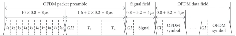
GI OFDMsymbol · · · GI symbolOFDM Figure4: Packet structure of the IEEE 802.11a standard.
times as slow as the LS-based soft detector, which indicates that the hybrid soft detector isabout10 times slower than the LS-based soft detector. We can also see that the LSD-based soft detector needs 120 times as many flops as the LS-based one, which means that the hybrid soft detector isabout 10 times faster than the LSD-based one. (This will be elaborated in the next section based on the parameters of our WLAN application.) Note that the new hybrid soft detector is more efficient for high SNRs than for low SNRs since at high SNRs the probabilities of ˆx(LS)=xˆ(SPD)are high and the chances of
using the computationally expensive LSD-based soft detector are low. Note also that the above analysis of the complexity is only intended to give a feeling about the efficiency of the hybrid soft detector and is by no means very accurate. More accurate analysis of the complexities, including those for SPD and LSD, is still an open topic.
We remark that the bad bit metrics can also be identi-fied by using the condition number (CN) ofHHH, and the
resulting soft detector can be referred to as the CN-hybrid soft detector. However, the CN-hybrid soft detector is infe-rior to its hybrid counterpart due to the following reasons. First, it is hard to determine a threshold for the CN. If the threshold is too high, many bad bit metrics from the LS-based soft detector will be used in the hybrid soft detector, which will lead to degraded performance. On the other hand, if the threshold is too low, the computationally expensive LSD-based soft detector will be used too often, which will re-sult in increased computational complexity. Second, a large CN does not necessarily result in detection differences be-tween SPD and the LS-based hard detectors. Neither does a small condition number guarantee the same detection result for the two hard detectors. As will be demonstrated using the simulation results in the next section, for a practical choice of CN, say 100, the CN-hybrid soft detector has a comparable (0.06×(25 + 95)=7.2 times as many flops as LS) complex-ity with the hybrid soft detector; yet, the performance of the former is inferior to the latter.
5. SIMULATION RESULTS
Our results obtained under the flat fading channel condition can be readily extended to the orthogonal frequency-division multiplexing (OFDM)-based WLAN systems operating over frequency-selective fading channels [21]. This is because for each subcarrier the channel is a flat fading one. In our simu-lations, we follow the IEEE 802.11a 5 GHz band high-speed WLAN standard [13] whenever possible.
The OFDM-based WLAN system, as specified by the IEEE 802.11a standard, uses packet-based transmission. Figure 4shows the packet structure specified by the standard.
Each packet consists of many OFDM symbols. Each OFDM symbol occupies 64 subcarriers, among which 48 are used for data symbols and 4 for pilot symbols. There are also 12 null subcarriers. The OFDM symbols are obtained via taking the inverse fast Fourier transform (FFT) of the data, pilots, and nulls on these subcarriers. The nominal bandwidth of the OFDM signal is 20 MHz and the I/Q sampling interval is 50 nanoseconds. Due to the fact that the modulation and de-modulation are done in the frequency domain, a frequency domain bit-level interleaver is used to segment the encoded bit sequence according to the transmission data rate and to scatter them over the 48 different data-carrying subcarriers. Before interleaving, an industrial standard constraint length 7 andRC =1/2 CC is employed to code the source bit
se-quence. In the IEEE 802.11a standard, the maximum trans-mission data rate is 54 Mbps; in this case the 64-QAM con-stellation is used and the channel coding rate is R = 3/4, which comes from puncturing the RC = 1/2
convolution-ally encoded sequence with the puncturing rateRP = 2/3.
The channel is assumed to be fixed during the packet trans-mission.
We consider doubling the maximum 54 Mbps transmis-sion data rate by using a BLAST system with two trans-mit and two receive antennas, that is, M = N = 2. This OFDM-based BLAST WLAN system is backward compat-ible with its SISO counterpart, with the packet structure shown inFigure 5. (See [21] for more detailed description of the MIMO system design.) In our simulations, each of theMN =4 time domain MIMO channels is generated ac-cording to the exponential channel model [22] with the root-mean-square spreading timetrmsbeing 50 nanoseconds; the
4 channels are statistically independent of each other. After FFT at the receiver, the channel matrix for each subcarrier has the same form as in (1), with the ¯k being the subcar-rier index in this case. This subcarsubcar-rier index is equivalent to the time index for time-varying flat fading channels since the channel for the OFDM-based WLANs is assumed to be fixed for the entire packet, with the changes across the subcarri-ers due to the delay time spreading. (Note that the intsubcarri-ersym- intersym-bol interference is avoided in the OFDM-based systems due to using the cyclic prefix [13].) We consider the case of per-fect channel knowledge, where the carrier frequency offset, symbol timing, channel response, and noise variance are all known in all our simulations; in practical applications, these parameters can be estimated via applying the channel param-eter estimation methods, such as those in [21,23,24,25], to the packet preambles.
IEEE 802.11 a compatible packet preamble Short training symbols
10×0.8=8µs
Long training symbol block 1 1.6 + 2×3.2=8µs t1 t2 t3 t4 t5 t6 t7 t8 t9t10
t1 t2 t3 t4 t5 t6 t7 t8 t9t10
GI2 T1 T2
GI2 T1 T2
Signal field 0.8 + 3.2=4µs
GI Signal GI Signal
Long training symbol block 2 1.6 + 2×3.2=8µs GI2 T1 T2 −GI2 −T1 −T2
OFDM data field 0.8 + 3.2=4µs
· · ·
GIOFDM symbol GIOFDM symbol
GIOFDM symbol GI OFDM symbol
Figure5: Packet structure for the OFDM-based BLAST WLAN system.
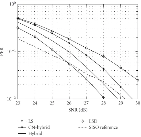
LS CN-hybrid Hybrid
LSD SISO reference
23 24 25 26 27 28 29 30
SNR (dB) 10−2
10−1
100
PE
R
Figure6: PER versus SNR comparisons for the soft detectors.
average energy is normalized to 1. For the OFDM-based BLAST WLAN system, we keep the same total transmission power and maintain the same subcarrier structure as its SISO counterpart.
We give two simulation examples to demonstrate the per-formance and computational complexity of our hybrid soft detector.
Example1 (Performance). The PER (one packet consists of
1000 bytes, which are contained in 19 OFDM symbols) is an important parameter for the OFDM-based WLAN sys-tems. (In an OFDM-based WLAN system, even if only one error occurs, the entire packet is considered to be wrong.) In Figure 6, we show the PER comparison for the LS-based soft detector, the CN-hybrid soft detector (with CN being 100), the hybrid soft detector, and the LSD-based soft detector as a function of SNR for the OFDM-based BLAST WLAN system at the 108 Mbps data rate. We also give the PER curve of using the soft detector for the SISO system at the 54 Mbps data rate as a reference. We can see from the simulation results that for the OFDM-based BLAST WLAN system, the performance of the hybrid soft detector is close to that of the LSD-based soft detector. We can also see that the hybrid soft detector outperforms its CN-hybrid counterpart. Moreover, the PER curve of the hybrid soft detector has nearly the same slope
CN-hybrid Hybrid
23 24 25 26 27 28 29 30
SNR (dB) 10−2
10−1
P
robabilities
o
f
u
sing
LSD
Figure7: Probabilities of using LSD in the hybrid and CN-hybrid soft detectors as SNR varies.
as the LSD-based one, which means that at high SNRs, the hybrid soft detector can offer much better performance than the LS-based one. Also, by comparing the solid line with the dashed line, we can see that if we use the hybrid soft detector at the receiver, we need about 1.5 dB more SNR to keep the same 10% PER (we are currently mostly interested in PERs of 10%) to double the data rate withM=N=2. Note that even with the need of this 1.5 dB extra SNR, that is, 1.5 dB more total transmission power, the PER performance of the OFDM-based BLAST WLAN system with the hybrid soft de-tector is still impressive since even if we wish to double the transmission data rate using two separate SISO systems over two different physical channels by doubling the bandwidth, we still need 3 dB extra SNR or total transmission power. If we consider the case of 1% PER, we can double the data rate with about 0.5 dBlesstotal transmission power.
Example 2 (Complexity). To facilitate the analysis of the
6. CONCLUDING REMARKS
We have proposed a hybrid soft detector with a good perfor-mance/complexity trade-offby combining the LS- and LSD-based soft detectors. The combination is performed LSD-based on comparing the outputs of SPD and the LS-based hard de-tector. To speed up the computation of SPD, we have also provided a tight sphere radius that can be used to guarantee the finding of at least one solution. Simulation results have shown that the performance of our hybrid soft detector is close to that of the LSD-based soft detector in our WLAN application. The new detector is about 10 times faster than the LSD-based and about 10 times slower than the LS-based soft detectors.
ACKNOWLEDGMENTS
We would like to thank the anonymous reviewers for their helpful comments which have helped improve the quality of this paper. This work was supported in part by the Na-tional Science Foundation Grant CCR-0097114 and the In-tersil Corporation Contract 2001056.
REFERENCES
[1] G. J. Foschini and M. J. Gans, “On limits of wireless commu-nications in a fading environment when using multiple an-tennas,” Wireless Personal Communications, vol. 6, no. 3, pp. 311–335, 1998.
[2] I. E. Telatar, “Capacity of multi-antenna Gaussian channels,”
European Transaction Telecommunications, vol. 10, no. 6, pp. 585–595, 1999.
[3] S. Lin and D. J. Costello, Error Control Coding, Prentice Hall, Englewood Cliffs, NJ, USA, 1982.
[4] J. G. Proakis, Digital Communications, McGraw-Hill, New York, NY, USA, 3rd edition, 1995.
[5] A. M. Tonello, “Space-time bit-interleaved coded modula-tion with an iterative decoding strategy,” inProc. IEEE VTS-Fall VTC 2000. 52nd, vol. 1, pp. 473–478, Boston, Mass, USA, 2000.
[6] J. J. Boutros, F. Boixadera, and C. Lamy, “Bit-interleaved coded modulations for multiple-input multiple-output chan-nels,” inProc. 6th IEEE International Symposium on Spread Spectrum Techniques and Applications, vol. 1, pp. 123–126, Parsippany, NJ, USA, September 2000.
[7] G. J. Foschini, “Layered space-time architecture for wireless communication in a fading environment when using multiple antennas,”Bell Labs Technical Journal, vol. 1, no. 2, pp. 41–59, 1996.
[8] G. D. Golden, G. J. Foschini, R. A. Valenzuela, and P. W. Wolniansky, “Detection algorithm and initial laboratory re-sults using V-BLAST space-time communication architec-ture,”Electronics Letters, vol. 35, no. 1, pp. 14–15, 1999. [9] Z. Liu and G. B. Giannakis, “Layered space-time coding for
high data rate transmissions,” inProc. IEEE Military Commu-nications Conference (MILCOM’ 01), vol. 2, pp. 1295–1299, McLean, VA, USA, October 2001.
[10] J. Liu and J. Li, “A simple soft-detector for the BLAST sys-tem,” inProc. Sensor Array and Multichannel Signal Processing Workshop (SAM’ 02), pp. 159–163, Rosslyn, Va, USA, August 2002.
[11] B. M. Hochwald and S. ten Brink, “Achieving near-capacity on a multiple-antenna channel,” IEEE Trans. Communications, vol. 51, no. 3, pp. 389–399, 2003.
[12] O. Damen, A. Chkeif, and J.-C. Belfiore, “Lattice code decoder for space-time codes,” IEEE Communications Letters, vol. 4, no. 5, pp. 161–163, 2000.
[13] IEEE 802.11a-1999, “IEEE Standard for information technology—telecommunications and information exchange between systems—local and metropolitan area networks— specific requirements—part 11: Wireless LAN medium ac-cess control (MAC) and physical layer (PHY) specifications— amendment 1: High-speed physical layer in the 5 GHz band,” IEEE, 1999.
[14] T. L. Marzetta and B. M. Hochwald, “Capacity of a mobile multiple-antenna communication link in Rayleigh flat fad-ing,” IEEE Transactions on Information Theory, vol. 45, no. 1, pp. 139–157, 1999.
[15] J.-C. Guey, M. P. Fitz, M. R. Bell, and W.-Y. Kuo, “Signal de-sign for transmitter diversity wireless communication systems over Rayleigh fading channels,”IEEE Trans. Communications, vol. 47, no. 4, pp. 527–537, 1999.
[16] J. Hagenauer, E. Offer, and L. Papke, “Iterative decoding of binary block and convolutional codes,” IEEE Transactions on Information Theory, vol. 42, no. 2, pp. 429–445, 1996. [17] G. Caire, G. Taricco, and E. Biglieri, “Bit-interleaved coded
modulation,” IEEE Transactions on Information Theory, vol. 44, no. 3, pp. 927–946, 1998.
[18] C. Z. W. H. Swetman, J. S. Thompson, B. Mulgrew, and P. M. Grant, “A comparison of the MMSE detector and its BLAST versions for MIMO channels,” inIEE Seminar on MIMO: Communications Systems from Concept to Implementations, pp. 19/1–19/6, London, UK, December 2001.
[19] A. M. Chan and I. Lee, “A new reduced-complexity sphere decoder for multiple antenna systems,” inProc. IEEE Inter-national Conference on Communications (ICC’ 02), vol. 1, pp. 460–464, New York, NY, USA, 2002.
[20] M. O. Damen, K. Abed-Meraim, and M. S. Lemdani, “Fur-ther results on the sphere decoder,” inProc. 2001 IEEE Inter-national Symposium on Information Theory, pp. 1–333, Wash-ington, DC, USA, June 2001.
[21] J. Liu and J. Li, “A MIMO system with backward compatibil-ity for OFDM-based WLANs,” EURASIP Journal on Applied Signal Processing, vol. 2004, no. 5, pp. 696–706, 2004. [22] N. Chayat, “Tentative criteria for comparison of modulation
methods,”Doc. IEEE 802.11-97/96, September 1997. [23] E. G. Larsson, G. Liu, J. Li, and G. B. Giannakis, “Joint
sym-bol timing and channel estimation for OFDM based WLANs,”
IEEE Communications Letters, vol. 5, no. 8, pp. 325–327, 2001. [24] J. Li, G. Liu, and G. B. Giannakis, “Carrier frequency offset estimation for OFDM-based WLANs,”IEEE Signal Processing Letters, vol. 8, no. 3, pp. 80–82, 2001.
[25] J. Liu and J. Li, “Channel parameter estimation and error re-duction for OFDM-based WLANs,” to appear inIEEE Trans-actions on Mobile Computing.
Jianhua Liureceived the B.S. degree in elec-trical engineering from Dalian Maritime University, Dalian, China, in 1984, the M.S. degree in electrical engineering from the University of Electronic Science and Tech-nology of China, Chengdu, China, in 1987, and the Ph.D. degree in electronic engi-neering from Tsinghua University, Beijing, China, in 1998. From March 1987 to Febru-ary 1999, he worked at the
he was also a Research Assistant at Tsinghua University. From February 1999 to June 2000, he worked at Nanyang Technological University, Singapore, as a Research Fellow. Since June 2000, he has been a Research Assistant in the Department of Electrical and Com-puter Engineering at the University of Florida, Gainesville, working towards a Ph.D. degree majoring in electrical engineering and mi-noring in statistics. His research interests include wireless commu-nications, statistical signal processing, and sensor array processing.
Jian Lireceived the M.S. and Ph.D. degrees in electrical engineering from The Ohio State University, Columbus, in 1987 and 1991, respectively. From April 1991 to June 1991, she was an Adjunct Assistant Profes-sor with the Department of Electrical Engi-neering, The Ohio State University, Colum-bus. From July 1991 to June 1993, she was an Assistant Professor with the Department of Electrical Engineering, University of