Article
A New Adaptable, Optical High-Resolution
3-Axis Sensor
Niels Buchhold * and Christian Baumgartner *
Institute for Health Care Engineering, Graz University of Technology, 8010 Graz, Austria
* Correspondence: [email protected] (N.B.); [email protected] (C.B.)
Abstract: This paper presents a new optical, multi-functional, high-resolution 3-axis sensor which serves to navigate and can, for example, replace standard joysticks in medical devices such as electric wheelchairs, surgical robots or medical diagnosis devices. A light source, e.g. a laser diode is affixed to a movable axis and projects a random geometric shape on an image sensor (CMOS or CCD). The software in the downstream microcontroller identifies the geometric shape’s center, distortion and size, then calculates X, Y, and Z coordinates. These coordinates can then be processed in attached devices. The 3-axis sensor is characterized by its very high resolution, precise reproducibility and plausibility of the coordinates produced. In addition, optical processing of the signal provides a high level of safety against electromagnetic and radio frequency interference. The sensor presented here is adaptive and can be adjusted to fit a user’s range of motion (stroke and force). This recommendation aims to optimize sensor systems such as joysticks in medical devices in terms of safety, ease of use, and adaptability.
Keywords: tactile sensors; assistive technologies; power wheelchair; medical systems; robotic; joystick; optical sensor
1. Introduction
The use of sensors as an interface between people and machines is becoming increasingly
important in our society. Joysticks can be operated practically in an intuitive manner and are found more and more often in a variety of controller systems as input devices. Areas of application such as
medical technology require a high level of safety during use. Moreover, a wide spectrum is necessary for individual users.
Especially for people with physical disabilities such as quadriplegia, spasticity, and muscular
dystrophy, using a sensor (joystick) is often a problem since the range of motion in terms of force and stroke undergoes constant changes as a result of such illnesses [1]. Depending on the specifications,
off-the-shelf joysticks have a pre-determined accuracy (resolution), a certain amount of force is required to deflect it, and a certain stroke to overcome the necessary paths either by a fixed or very
limited amount. Adapting the sensor to one individual is expensive and in some cases impossible when the user’s range of motion and strength is affected by changes in temperature [2]. Standard
joysticks are generally 2-dimensional control systems for the x and y directions. In order to steer in the z direction, the controller is turned or an additional control element is required. Physically disabled people with spinal cord injury (SCI) [3] usually do not have the fine motor ability required
to carry out such an action. A simple push along the z-axis is more likely to be possible. The sensor presented here can adapt to the desired strength and range of motion. Thus, there is no need for costly
There are currently 250,000 people living in the United States today with spinal injuries. A total of 47% of them are injured between C1 and C7 in the cervical spine area, rendering them quadriplegic. Each year, 11,000 people suffer a spinal injury [4,5]. In addition to this, there are muscular diseases
such as muscular dystrophy. This disease affects between 1 in 3,500 to 6,000 male babies per year in the United States [6]. These diseases usually require a custom input device in order to enable users
to operate electric wheelchairs or computers. However, the sensor can also be adapted to healthy users in the areas of diagnostic devices and surgical robotics. Thus making it possible to achieve a
higher level of user safety and precision while work is performed. If, for example, a powered wheelchair is used, new control systems such as eye tracking, voice control, and brain-computer
interfaces tend to be problematic [7-10]. These types of input methods make it difficult to perform precise and complex control actions simultaneously. Voice controls can usually only process one
command at a time and are unreliable in loud environments [11]. The exponential progression of the spring force and the very limited movement of the sensor axis generates a natural force feedback [12]. The user thus receives physical feedback pertaining to the deflection movement.
The introduced sensor’s potential areas of application can be expanded without limits. In addition to
medical applications fields such as automotive, aeronautical, aerospace, marine, and military in particular are conceivable here. The applied optical approach substantially increases safety of use.
Disruptive factors such as electromagnetic (EMI) and radio frequency interference (RFI) or differences in temperature have a marginal affect on the sensor if at all. Because the sensor can be
manufactured very inexpensively, the consumer area is also an interesting option. With its very limited stroke, the operation and response time is significantly higher than that of off-the-shelf joysticks.
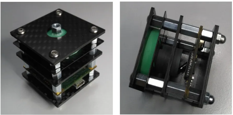
This paper introduces the prototype’s hardware (see Figure 1) of a new optical, multi-functional,
high-resolution 3-axis sensor and describes how it works. In addition, the integrated algorithms and software tools are presented and discussed in detail.
2. Hardware of the 3-axis sensor
2.1 Basic construction
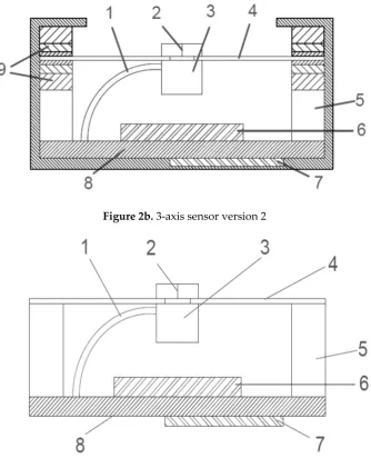
The sensor consists of a force transducer 2 and a projection unit 3, which is firmly affixed to a
movement carrier 4 (Figure 2). An image sensor is positioned underneath the projection unit at a set spacing. The angle of the movement carrier to the image sensor changes as a result of force applied to the force transducer. In doing so, the position of the projection on the image sensor shifts. Based
on the position, size, and distortion of the projection, the current x, y, and z coordinates are calculated. This happens in relationship to the degree the angle changes and the pressure on the axis.
Figure 2a. 3-axis sensor version 1
Figure 2c. 3-axis sensor version 4
The 3-axis sensor consists of the following components:
1. power supply line, projection unit 2. force transducer
3. projection unit 4. movement carrier
5. spacer 6. image sensor
7. microcontroller 8. circuit board
9. polymer sandwich or firmly attached 10. mirror
11. laser beam
2.2 Projection unit and image sensor
In its simplest construction, the projection unit consists of a laser diode with a downstream
plano-convex lens [13]. This configuration can also be substituted by a collimator lens [13] and a shape template. The image sensor is positioned underneath the projection unit at a set spacing. Depending
on the application and the image sensor that is used, frame rates up to 120fps can be achieved. The sensor’s maximum resolution depends on the image sensor type. For example, when using a ½” sensor with 1280 (H) x 1024 (V) pixels, SXGA/1.3 MP [14], without further calculation, 1280/2= 640
digits (H) and 1024/2=512 digits (V) for each direction can be achieved. When sub-pixels (gray tones) are included in the calculation and the resulting pool of light is interpolated, at least two decimal
places can be added. The resolution is thus increased 100-fold with a resolution of 64,000 (H) und 51,200 (V) available in each direction. When using an off-the-shelf 18.1 MP sensor with 4912 (H) x
3684 (V) pixels [15], based on the calculation mentioned above, there is a resolution of 245.600 (H) x 184.200 (V) digits in each direction. These values should be sufficient even for highly sensitive
2.3 Different versions
Depending on the purpose of use, the sensor can be operated in different variations:
Version 1 (see Figure 2a): The movement carrier is positioned in a polymer sandwich and consists of a rigid material such as steel or carbon fiber reinforced polymer (CFRP). Through the force picked up by the force transducer, the movement carrier tilts. The degree of tilt depends on the force being
applied and the polymer’s shore hardness (Figure 3).
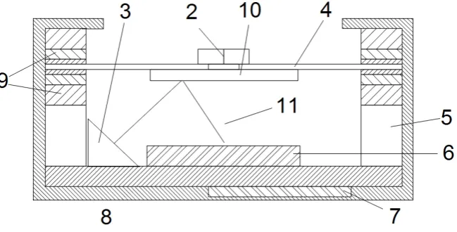
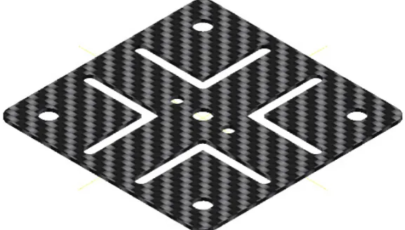
Version 2 (see Figure 2b): The movement carrier is manufactured out of elastic material (e.g. CFRP in
various strengths of 0.45 mm to 2 mm). The movement carrier is rigidly affixed to the casing and withstands bending and torsion. The cutout illustrated in Figure 4 is conducive to the movement
carrier’s deformation behavior.
Version 3: The same as Version 2 but includes an additional polymer cushion above the movement
carrier.
Version 4 (see Figure 2c): The projection unit, which produces images, is replaced by a mirror. In
order to generate a projection on the image sensor, the projection unit is affixed to the circuit board next to the image sensor and projects back over the mirror to the image sensor. The movement carrier’s changed angle causes the projection to reposition according to the forces acting on the
projection.
Figure 4. CFRP movement carrier version 3
2.4 Movement carrier
The movement carrier is selected depending on the application and the desired input force
spectrum. In version 1, a rigid material such as steel (diameter > 1 mm) or CFRP (diameter > 1.5 mm)
is integrated. In versions 2 and 3, flexible materials such as CFRP (0.3 - 1.1 mm) are used. The
materials used in version 2 and 3 should be characterized by excellent spring behavior, which is why CFRP is predestined for this application.
2.5 Polymer sandwich
The movement carrier is positioned in a polymer sandwich in version 1. The movement carrier’s spring is achieved through a particular arrangement of polymer layers. As a result, the Shore
hardness increases (soft -> hard). Owing to the polymer arrangement (pos. 9) shown in Figure 2, the movement carrier is capable of absorbing a large spectrum of forces upon it (approx. 1 g to 5 kg). Due
to the individual layer’s varying degrees of Shore hardness, each becomes active under different forces. Once a layer’s maximum compression is reached, the layer with the next degree of hardness becomes active and takes on the movement until it too reaches its maximum compression and so on.
3. Sensor operations
3.1 Fundamentals
When forces act on the movement carrier’s force transducer, the movement carrier changes its
tilt and/or the spacing between it and the image sensor below. In doing so, the projection unit, which is firmly affixed to the movement carrier, generates an image of a filled circle on the image sensor
Figure 5a. Complete frame without image processing
Figure 5b. Complete frame with image processing to binary mode
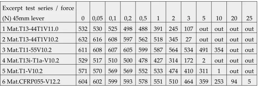
The movement carrier’s spring occurs either through the arrangement of the polymer layers in version 1 or the resilience of the material used as in version 2 and version 3. Table 1 and Figure 6
show the deflection relative to the applied force. Different polymer arrangements and types are shown here as examples. Due to the fact that the measurement curves are identical in both directions,
the measurement was carried out for one direction only. Force was applied by a 45 mm lever. In doing so, relatively soft polymer layers were used and a force up to 25 N was measured. “out” means
that the light circuit has left the active sensor field.
Table 1. Selected measurements with different materials and versions.
Excerpt test series / force
(N) 45mm lever 0 0,05 0,1 0,2 0,5 1 2 3 5 10 20 25
1 Mat.T13-44T1V11.0 532 530 525 498 488 391 245 107 out out out out
2 Mat.T13-44T1V10.2 632 616 608 597 562 518 345 27 out out out out
3 Mat.T11-55V10.2 611 608 607 605 599 587 564 534 491 354 out out
4 Mat.T13i-T1a-V10.2 529 517 510 500 478 427 314 172 2 out out out
5 Mat.T1-V10.2 571 570 569 569 552 533 474 410 311 1 out out
Figure 6. Visualized, measured values from table 1
3.2 Projection, image analysis, data output
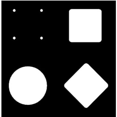
As shown in Figure 7, geometric shapes of all kinds can be used for the projection (Figure 7a, 7b, 7c are shown in schematic form).
Figure 7a. Various projection images schematically
0 200 400 600 800 0 0.05 0.1 0.2 0.5 1 2 3 5 10 20 25
532 530525
498488 391 245 107 632 616 608 597 562 518 345 27
611 608 607605 599
587 564 534 491 354 529 517 510 500 478 427 314 172 2
571 570 569569
552 533 474 410 311 1 604 602 599
593 578 551 510 464 359 253 94 5
Digits without interpolation
force
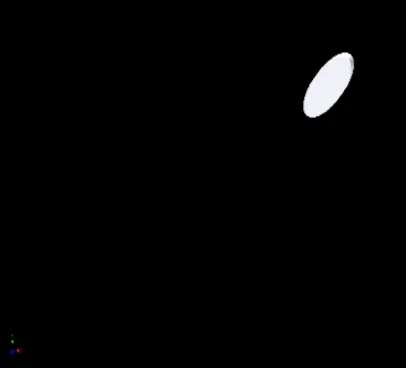
Figure 7b. Deflection of the circle (figure 5b) on the x-axis schematically
Figure 7c. Deflection of the circle (figure 5b) on the x- and y-axis schematically
As an example, the simplest geometric shape (full circle see Figure 7a on bottom left) was used for
the prototype presented here. By using four dots (see Figure 7a top left) more than three axes can be measured. Figure 5 shows the resting state. As a result of the manufacturing allowances, it does not matter whether the projection of the circle is exactly in the middle of the image sensor or slightly
off-center. The absolute zero position or resting position, is set during calibration. The calibration process usually takes place only once after production. This avoids higher production costs since the
manufacturing allowances are relatively insignificant. Figure 7b shows the movement carrier in the x direction. A distorted ellipsis is produced due to the angle of the light. In addition, the diagonal
deflections in the x and y directions are shown in Figure 7c. The image analysis software first searches for the previously defined shape on the captured image. In order to reduce computation time, once
the image is found, only the area of interest [16] around the object is examined. This approach increases the processing time substantially. If the image is not found, the entire image is searched again. The sub-pixels’ brightness values are then analyzed and the center of the projection is
calculated through interpolation. This increases the accuracy by two decimal places. The project focus is set in such a way that the focal point is below the image sensor’s surface in a state of rest. As a
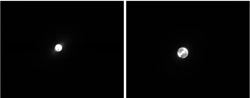
without pressed z-axis). A pull of the z-axis decreases the size of the projection, while a push of the z-axis enlarges the projection (see Figure 8b).
Figure 8a. Focusing without pressed z-axis
Figure 8b. Focusing with pressed z-axis
The image analysis software detects either the smaller circle of light or the larger circle of light and
then calculates the current z-axis coordinates (see Figure 9). These highly accurate coordinates are then passed on to the downstream system. While doing this, serial values or different bus protocols
(CAN, SPI, I2C, analog voltage, etc. in the next step of development) can be generated.
3.3 Plausibility check
The sensor should also be utilized in highly sensitive or safety-related areas. To do so, a
plausibility check is performed. The projected shape is naturally distorted during the projection (Figure 7b and 7c). When the projected circle moves away from the middle of the image sensor, the
circle becomes an ellipsis. Since an ellipsis has two focal points F1 and F2, the resulting spacing is calculated. The spacing of the focal points increases the further the movement carrier is moved. In
order to identify the maximum allowable spacing between F1 and F2, the movement carrier is moved in each direction once with the maximum amount of force permitted. Ideally, it should be a circular
movement with the maximum force permitted. This circular movement can be performed either manually or with a calibration device. During the calibration movement, the maximum distortions and their positions are extracted and saved permanently. All of the detected projections are compared
to the previously saved images during normal operation. When a maximum position or a maximum distortion is exceeded, measures can be taken to protect the downstream system from malfunctions.
Additionally, other special cases can be identified. In the event that the projection unit leaves its position of rest due to a hardware defect without being moved, the resulting projection would be
distortion-free in another position. This is considered an error because it is not possible to detect a distortion-free projection at other coordinates such as the original position of rest. The plausibility
check can be expanded depending on the performance of the image sensor and the microcontroller that are in use. In addition, motion patterns or speeds can be analyzed and checked for plausibility.
3.4 Individually adjustment of the des 3-axis sensor
Due to the various symptoms of individual medical conditions, different input forces and input
lifts are required. Depending on the specifications, standard joysticks have a pre-determined accuracy (resolution), a certain amount of force is required to deflect it, and a certain stroke to
overcome the necessary paths by a fixed amount. As described in the introduction, certain groups of physically disabled people are unable to use standardized joysticks. The issue has to do with this group of individuals’ range of motion in terms of force and stroke. Moreover, the existing range of
motion is affected by outside influences such as the ambient temperature [2]. A permanent readjustment of the sensor would be necessary for long-term use. In order to adapt the sensor to the
patient’s motion and stroke movement abilities the user moves the 3-axis sensor at least once in each direction with a circular movement. The z-axis can also be configured through vertical pressure and
tension applied to the movement carrier. The maxima of the x-, y-, and z-coordinates are then saved. As an example, the force or the stroke of a patient suffering from muscular disease was documented.
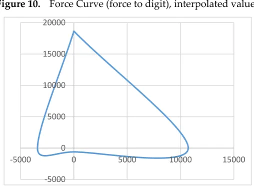
Figure 10. Force Curve (force to digit), interpolated values
When a reference was established (deflection and force to digit) Figure 10 can be used to directly determine the force and stroke the patient applied. The relationship between stroke and the change
in coordinates is of course just as dependent on the length of the lever used. In a test case, the patient was able to carry out the following deflection, i.e. force (the z-axis is not taken into account here)
(Table 2)
Table 2. Patient measurements and applied force
direction to max. digits approx. force
forward 18.653 3.92N
back 611 0.07N
left 3411 0.74N
right 10.724 2.12N
These values cannot be transmitted directly to a power wheelchair. The patient would simply drive the wheelchair forwards and to the right, while traveling at a sufficient speed. The values achieved
for reverse and left are not sufficient to move the wheelchair. Suitable factors or divisors can provide the desired consistent output signal. Example: Common output values are in the 10 bit range
(measured value / 1024 = divisor) (Table 3).
Table 3. Patient measurements and calculated divisor
direction to max. digits divisor
forward 18.653 18,22
back 611 0,60
left 3411 3,33
right 10.724 10,47
-5000 0 5000 10000 15000 20000
All of the coordinates documented during use for this user, then have to be converted with the divisor
to attain a consistent output signal.
Example Calculation:
All values are multiplied by 100 by the interpolation of the image (Right value see Table 2; 10 bit
output signal; image sensor 1280 x 1024).
= 128.000 ; Maximum resolution in horizontal direction;
= ;
= 64.000 ; Half resolution each direction;
= 63.891 ; Measured neutral value;
= 500 ; Hysteresis for a neutral window in the middle
position;
= 74.615 ; Learned maximum value to the right;
= . − ;
= 10.724 ; Absolut maximum value to the right;
= 1024 ; Desired maximum output value;
=
2
= 512 ; Desired maximum output value each direction;
=
512 digits ;
= 20,95; Calculated divisor;
= 4.200 ; Example value to the right;
=
20,95 ;
= 200 Digital output value;
4. Results and Discussion
The sensor described here is in the prototype stage. Due to the optical implementation, it should be resistant to outside interference such as EMI or RFI. In version 1, a hot vulcanizing 2K silicone rubber is used that has optimal spring properties. Unfortunately, this ability is not sufficient to
achieve a satisfactory result. Depending on the axis deflection, the neutral position is more or less difficult to reach. This circumstance can be compensated for because the neutral values can be
reproduced exactly. In versions 2 and 4, the movement carrier is made of CFRP and firmly affixed to the casing. Compared to fiber-reinforced polymer (AFRP) and glass-fiber reinforced polymer (GFRP),
described above and the spring precision is at +- 2 digits (without interpolation, image sensor 1.3 MP).
The climate chamber was successfully completed (-30 degrees to 80 degrees). The deviation was at +- 1 digit (without interpolation, image sensor 1.3 MP). The first tests under laboratory conditions were
successfully completed. During the tests, the was used in place of a mouse and to operate a power wheelchair [18]. As long as a physically disabled patient still has some type of physical capability
(hand, finger, foot, toe, head, chin, etc.), it should be possible to use this sensor. Owing to the sensor’s ability to learn there are no additional costs. If the clinical symptoms change for the worse, the sensor
can be adapted to the new conditions immediately.
Thanks to the high resistance to interference, other areas of application in addition to the medical sector could have great potential such as automotive, aeronautics, aerospace, marine and military. Owing to its resolution and reproducibility (movement to digits), geophysical sensors could also be
replaced by this sensor. A screwed-on rod or ball to receive the force can come into a resonance oscillation when a defined oscillation frequency acts on the sensor. Thus the system can begin to
“vibrate”. This particular case can also occur in off-the-shelf joysticks. To compensate, a polymer ring can be installed above the movement carrier (version 3), which functions as a shock absorber and
dampens vibrations. For technical reasons, the force to be exerted increases exponentially to the deflection causing a natural force feedback. Noise in the image sensor is also another issue. In a state
of rest, the coordinates change by up to 2/100 digits (with interpolation, image sensor 1.3MP). For the most part, this camera noise can be removed on a mathematical basis [16].
5. Conclusions
Our results show the feasibility and practicability of the new optical, multi-functional, high-resolution 3-axis sensor. Compared to standard, high-high-resolution sensors (resistive, inductive, or
capacitive) the sensor presented here works on a completely digital basis. No compensation is required to adapt the sensor to fluctuations in temperature, for example. Depending on the intensity
of the plausibility check, the software requires a substantial amount of calculation time. The version shown here, the focus of the calculation can be on maximum frame rate or on maximum resolution. Because the different uses and applications usually only require one focus, the sensor’s software can
be optimized for each purpose. The current prototype can achieve a maximum resolution of 60 fps. When using the area of interest (AOI) function, 150 fps can be processed. This problem can be solved
by using faster image sensors and faster microcontrollers. In addition, the sensor can also work with more than 3-axes, for example, when a square is used as the projected shape. The image analysis
software then also detects a rotary movement of the axis, the computation time however increases substantially.
Conflicts of Interest: The authors declare no conflicts of interest except that the device described in this paper is patent and PCT pending.
References and Notes
1. Cowan, R.E.; Fregly, B.J.; Boninger, M.L.; Chan, L.; Rodgers, M.M.; Reinkensmeyer, D.J. Recent trends in assistive technology for mobility. Journal of neuroengineering and rehabilitation 2012, 9, 1.
2. Balon, D. Facts About Myotonic Muscular Dystrophy. MDA Muscular Dystrophy Association Inc.: 2009; p 5.
3. Ramstein, C. In Combining haptic and braille technologies: design issues and pilot study, Proceedings of the second annual ACM conference on Assistive technologies, 1996; ACM: pp 37-44.
4. National Spinal Cord Injury Statistical Center. Spinal cord injury facts and figures at a glance. The journal of spinal cord medicine 2010, 33, 439.
5. Ginop, M. Spinal Cord Injury Facts & Statistics. MCG Web Development, Inc: SCI-Info-Pages, 2016; p
1.
6. Emery, A.E. The muscular dystrophies. The Lancet 2002, 359, 687-695.
7. Wolpaw, J.R.; Birbaumer, N.; Heetderks, W.J.; McFarland, D.J.; Peckham, P.H.; Schalk, G.; Donchin, E.; Quatrano, L.A.; Robinson, C.J.; Vaughan, T.M. Brain-computer interface technology: a review of
the first international meeting. IEEE transactions on rehabilitation engineering 2000, 8, 164-173. 8. Kim, K.-N.; Ramakrishna, R. In Vision-based eye-gaze tracking for human computer interface, Systems,
Man, and Cybernetics, 1999. IEEE SMC'99 Conference Proceedings. 1999 IEEE International Conference on, 1999; IEEE: pp 324-329.
9. Malkin, J.; House, B.; Bilmes, J. In Control of simulated arm with the vocal joystick, CHI 2007 Workshop
on Striking a C [h] ord: Vocal Interaction in Assistive Technologies, Games, and More, 2007; pp 535-555.
10. House, B.; Malkin, J.; Bilmes, J. In The VoiceBot: a voice controlled robot arm, Proceedings of the SIGCHI Conference on Human Factors in Computing Systems, 2009; ACM: pp 183-192.
11. Martens, C.; Ruchel, N.; Lang, O.; Ivlev, O.; Graser, A. A friend for assisting handicapped people. IEEE Robotics & Automation Magazine 2001, 8, 57-65.
12. Encarnacao, J.; Gobel, M.; Rosenblum, L. European activities in virtual reality. IEEE Computer Graphics and Applications 1994, 14, 66-74.
13. Fischer, R.E.; Tadic-Galeb, B.; Yoder, P.R. Optical system design. 2nd ed.; McGraw-Hill: New York,
2008; pp 115-117,122.
14. IDS Imaging Development Systems GmbH. UI-1241LE.
https://de.ids-imaging.com/store/ui-1241le.html Available online: (accessed on 11 November 2016). 15. IDS Imaging Development Systems GmbH. UI-3591LE.
https://de.ids-imaging.com/store/catalogsearch/result/?q=UI-3591LE Available online: (accessed on 11 November 2016).
16. Priese, L. Computer Vision: Einführung in die Verarbeitung und Analyse digitaler Bilder. Springer-Verlag: 2015; pp 94,95,126,134,109,110.
18. Dynamic Controls. The DX2 System
https://dynamiccontrols.com/en/dealers/products/dx2/the-dx2-system Available online: (accessed on 10 October 2016).