TRACKING AND CONTROL IN
MULTI-FUNCTION RADAR
by
Joseph Mackay Butler
A thesis submitted to the University of London for the Degree of
Doctor of Philosophy in Electronic Engineering
Department of Electronic and Electrical Engineering
University College London
August 1998
ABSTRACT
The phased array multi-function radar is an effective solution to the requirement for
simultaneous surveillance and multiple target tracking. However, since it is performing
the jobs usually undertaken by several dedicated radars its radar time and energy
resources are limited. For this reason, and also due to the large cost of active phased
array antennas, it is important for the strategies adopted in the control of the radar to be
efficient. This thesis investigates and develops efficient strategies for multi-function
radar control and tracking. Particularly the research has focused on the use of rotating
array antennas and simultaneous multiple receive beam processing.
The findings of the research challenge the traditional view that three or four fixed
(static) array faces is the best antenna configuration for a multi-function radar system.
By developing novel methods for the comparison of systems utilising different antenna
configurations it is shown that a rotating array multi-function radar performs the
surveillance function with a greater efficiency in its use of radar time than a static array
system. Also, a rotating array system benefits from the ability to distribute the radar
resources over the angular coverage in a way that is impossible with a static array
system. A novel strategy is presented to achieve this, which allows the rotating array
system to better support the realistic situation of a high concentration of radar tasks in a
narrow angular sector.
It is shown that the use of broadened transmit beams coupled with simultaneous
multiple narrow receive beams can eliminate the compromise on radar beamwidth
between the surveillance and tracking functions that is associated with multi-function
radars. This technique would allow construction of multi-function radar systems with
narrow beamwidths, giving improved tracking performance, without extending search
frame times excessively.
Efficient tracking strategies for both static array and rotating array multi-function radars
are developed. They are applied through computer simulation to demonstrate tracking of
highly manoeuvrable targets with a narrow beam multi-function radar. Track robustness
is attained through the use of multiple beam track updating strategies at little cost in
ACKNOWLEDGEMENTS
Firstly, my thanks must go to Professor H.D. Griffiths. His help and supervision
throughout this research have been unending, and he has made my stay at UCL both
pleasant and memorable. Thanks too must go to Dr A.R. Moore and Mr W.A. Levett
from DERA Portsdown, who have aided and encouraged me since I first entered the
field of radar. Without their active support, completion of this research would not have
been possible. I would also like to express my gratitude to Professor K. Milne and
Professor R. Benjamin for their expert advice and stimulating discussions during their
visits to UCL.
Also at DERA Portsdown, thanks are due to G. Rhees, E. Brice, P. Donnely, and in
particular to M. Deighton and P. Clements whose help has gone beyond that which
could have been expected. At BAeDS my thanks go to W.Stafford and S.Noyes.
Finally, I would like to give thanks to the friends and colleagues who have contributed
either directly or indirectly to this thesis, and have put up with me throughout it.
Particularly thanks go to R. Bullock, G. Davidson, W. Lee, H. Read and L. Vinagre
from the Antennas and Radar Group at UCL, C. Andrew, R. Maunder, A. Ridehalgh and
F. Read, for their complete lack of interest in the field of radar and the healthy antidote
which they provided, my ever patient family E. Butler, J. Butler, E. Cooper and D.
Cooper, and last to V.A. Byram who has proof read this thesis, and has helped more and
MULTI-FUNCTION RADAR TRACKING AND CONTROL
TABLE OF CONTENTS
1 INTRODUCTION
17
I.! Historical background 17
1.2 Objectives 18
1.3 Thesis Layout 19
1.4 Novel Aspects 21
2 AN OVERVIEW OF MULTI-FUNCTION RADAR
22
2.1 Background 22
2.2 Multi-function radar functions 23
2.2.1 Search 24
2.2.2 Plot confirmation 25
2.2.3 Track initiation 25
2.2.4 Track maintenance 26
2.2.5 Functional flexibility 27
2.3 Underlying theory of multi-function radar 27
2.3.1 Radar systems 27
2.3.2 Phased arrays 34
2.3.3 Multi-function radar system aspects 39
2.4 Benefits of using a multi-function radar 44
2.5 Penalties of using a multi-function radar 45
2.6 Static versus rotating systems 47
3 MESAR: AN EXAMPLE MULTIFUNCTION RADAR SYSTEM
49
3.1 Introduction 49
3.2 Array face and transmit/receive modules 51
3.3 MESAR adaptive beamforming 52
3.4 Radar control 53
3.5 Adaptive signal processing and waveform generation 54
3.6 The plot processor and tracker 55
3.6.1 Plot processing 55
3.6.2 Track filtering 55
3.6.3 Adaptive track update rate 56
3.6.4 Adaptive transmit energy 57
3.6.5 MTI velocity response matching 57
3.7 Trials results 57
3.7.1 Multi-function operation 58
3.7.2 Tracking 58
3.8 Summary 60
4 THE IMPACT OF VARIABLE BEAM WIDTH AND MULTIPLE BEAM
PROCESSING ON MULTI-FUNCTION RADAR
61
4. I Introduction 61
4.2 Generating a broadened main lobe antenna pattern 62 4.3 Processing of simultaneous multiple receive beams 64
4.4 Calculation of the search function time 65
4.4.1 Static phased array multi-function radar system 66 4.4.2 Rotating phased array multi-function radar system 71
4.5 Search time in a noise limited environment 76
4.5.1 Dwell time compensation 79
4.6 Search time in a clutter limited environment 82
4.7 Impact on the tracking functions 85
4.8 Conclusions 86
5 RESOURCE MANAGEMENT IN STATIC AND ROTATING ARRAY
MULTIFUNCTION RADAR 89
5. 1 Introduction 89
5.2 Resource management and task scheduling objectives 91 5.3 Task scheduling in a static array multi-function radar 92
5.3.1 Background 92
5.3.2 The MESAR algorithm 93
5.3.3 The modified MESAR algorithm 97
5.3.4 Simulation architecture 98
5.3.5 Scheduling using a simple two sector surveillance system 100 5.3.6 Scheduling using the MESAR surveillance volume 104 5.3.7 Plot confirmation latency using the MESAR scheduler 109 5.4 Task scheduling in a rotating array multi-function radar 110
5.4.1 Background 110
5.4.2 An algorithm for task scheduling in a rotating multi-function radar system 114 5.4.3 Beam search patterns with a rotating multi-function radar 118 5.4.4 Results with the rotating multi-function radar task scheduler algorithm 119 5.4.5 Other resource management issues for a rotating multi-function radar 123 5.5 Penalty functions and fuzzy logic for efficient scheduling 124
5.5.1 The use of fuzzy logic 125
5.6 Conclusions 126
6 ADAPTIVE TRACKING IN MULTIFUNCTION RADAR 129
6. 1 Introduction 129
6.2 Tracking of manoeuvring targets with a narrow beam adaptive tracker 130 6.2.1 Simplified analysis of tracking manoeuvring target with a narrow beamwidth 131 6.3 Allocation of resources in tracking for a static array system 134 6.3.1 Allocation of resources for tracking in MESAR 135 6.3.2 Parameter optimisation for allocation of resources in the ELRA adaptive tracking
system 136
6.3.3 Comparison of the two strategies 139
6.4 Development of an adaptive tracking system simulation model 140 6.4.1 Modelling of the target measurement process 140
6.4.2 Kalman filtering 141
6.4.3 Augmenting the constant velocity Kalman filter for manoeuvring targets 145
6.4.4 Adaptive update rate strategy 150
6.4.5 Adaptive transmitted waveform energy 152
6.4.6 Missed detections and declaration of lost track 152 6.4.7 Development of a multiple beam track update strategy 152 6.4.8 Development of a rotating array track update strategy 154 6.4.9 Validation and testing of the adaptive tracking system simulation model 158
6.5 Results 159
6.5.1 A summary of the results collected 159
6.5.2 Single beam static array multi-function radar tracker 161 6.5.3 Multiple beam static array multi-function radar tracker 167 6.5.4 Single beam rotating array multi-function radar tracker 171 6.5.5 Multiple beam rotating array multi-function radar tracker 177 6.5.6 Comparison of static and rotating array tracker performance 182
7 A ROTATING, NARROW BEAM WIDTH MULTI-FUNCTION RADAR
SYSTEM
186
7. I Introduction 186
7.2 Requirement 187
7.3 Antenna configurations considered 188
7.4 Analysis of time budget and free space detection performance 189
7.4.1 Surveillance 189
7.4.2 Tracking 192
7.4.3 Summary 196
7.5 Conclusions 197
8 CONCLUSIONS AND FURTHER WORK
199
8.1 Summary 199
8.2 Evaluation of static array, rotating array and variable beam pattern multi-function radar 201 8.3 Resource management of static and rotating array multi-function radar 203
8.4 Adaptive tracking in multi-function radar 206
9 REFERENCES
208
APPENDIX A: THE BENCHMARK TRACKING PROBLEM
214
APPENDIX B: STATIC ARRAY TRACKER MONTECARLO
SIMULATION RESULTS
219
APPENDIX C: ROTATING ARRAY TRACKER MONTECARLO
SIMULATION RESULTS
227
LIST OF FIGURES
Figure 2-1 Functions of a multi-function radar for naval air defence ____________________________ 24 Figure2-2 The closed loop multi-function radar tracker_______________________________________ 26 Figure2-3 A simplified block diagram of a typical radar ______________________________________ 28 Figure 2-4 Monopulse antenna patterns and error signals. (a) overlapping antenna patterns, (b)
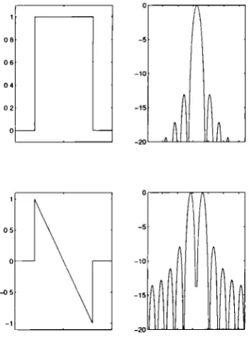
difference antenna pattern, (c) sum antenna pattern, (d) error signal _______________________ 31 Figure 2-5 Weighting functions for minimum monopulse estimation error, and the associated beam
patterns 32 Figure 2-6(a,b) A 2 dimensional Taylor weighting function, and its associated antenna pattern ______ 33 Figure 2-7 A Bayliss weighting function in one dimension and a Taylor weighting function in the other,
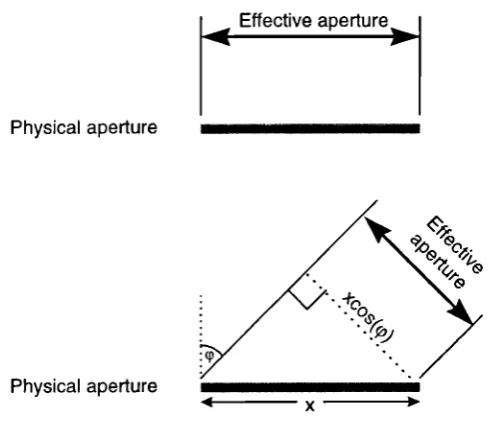
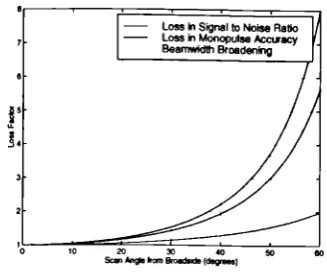
andits associated antenna pattern ___________________________________________________ 33 Figure 2-8 Generation of a phase front with no relative change in phase between each element ______ 36 Figure 2-9 Generation of a phase front with a constant phase change between adjacent elements 36 Figure2-10 Change in effective aperture with scan angle______________________________________ 37 Figure 2-1J(a,b) Beam broadening, loss in signal to noise ratio, and loss in monopulse accuracy as a
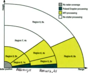
functionof scan angle ___________________________________________________________ 39 Figure 2-12 A cross section through a hemispherical search volume, showing sectored coverage with
regionnumber and frame time ______________________________________________________ 41 Figure 2-13(a-e) Angular and temporal variation in multi-function radar detection performance_____ 41 Figure2-14 A digital beamformer ______________________________________________________ 43 Figure3-1 The MESAR multi-function radar______________________________________________ 50 Figure 3-2 A simplified block diagram of the MESAR system _________________________________ 51 Figure3-3 The thinned MESAR array ___________________________________________________ 51 Figure 3-4 A simplified block diagram of the MESAR digital adaptive beamformer________________ 53 Figure 3-5 Adapted and unadapted beam patterns in the presence ofjammers____________________ 58 Figure 3-6 The MESAR PPI display, showing a recently initiated track_________________________ 59 Figure3-7 Adaptive update rate tracking ________________________________________________ 59 Figure3-8 Track splitting function________________________________________________________ 60 Figure 4-I(a,b,c,d) Synthesis of a broadened main lobe antenna pattern using Milne's method, showing
broadening of the scan pattern main lobe by (a) a factor of 2, (b) afactor of 4, (c) afactor of 6, (d) a factor of 8. Blue line shows the scan pattern, red line shows the desired pattern, green line shows therealisable pattern. ____________________________________________________________________ 63 Figure 4-2 Example tx and rx beam formations using simultaneous multiple beam processing _______ 64 Figure4-3 The UV space coordinate system and equations_____________________________________ 67 Figure 4-4 (a) A visualisation of UV space, showing beam broadening, (b) the same visualisation
showinga triangular lattice of beams_________________________________________________ 67 Figure 4-5 The relationship between the uv and real world coordinate systems, and the associated
equations 68
Figure 4-6(a, b) A comparison of lines of constant azimuth and elevation for (a) a vertical array, and (b) anarray inclined 15° back from vertical_____________________________________________ 69 Figure 4-7 Beam directions in UV space, using MESAR as an example _________________________ 69 Figure 4-8 (a) MESAR coverage limits in UV space, (b) Beam dwell time plotted as height above the UV
plane 70
Figure 4-9 (a) Number of beams, and (b) average beam dwell times as a function of beamwidth. Crosses represent answer from exact calculation of all beam directions and dwell times, the line represents theestimate from the UV method outlined above ________________________________________ 71 Figure 4-10 A visualisation of the rotating UV space, and the associated equations ________________ 72 Figure 4-11 Lines of constant azimuth and elevation in the rotating UV space, for a vertical array 73 Figure 4-12 (a, b, c) Lines of constant azimuth and elevation in the rotating UV space, for arrays inclined
backfrom vertical (a)30°, (b)60°, (d)90° ____________________________________________ 73 Figure 4-13 Beam directions in rotating UV space, using a MESAR search configuration as an example74 Figure 4-14 (a) MESAR coverage limits in rotating UV space, (b) Beam dwell time plotted as height
abovethe rotating UVplane ______________________________________________________ 75 Figure 4-15 (a) Number of beams, and (b) average beam dwell times as afunction ofbeamwidth,fora
above 76 Figure 4-16 The example surveillance coverage volume for comparison of different multi-function radar
antennaconfigurations ________________________________________________________________ 76 Figure 4-17 (a,b,c) 0'-60° elevation search sector plotted in (a) UV space for a 4faced multi-function
radar scanning to ±450, (h) UVspace for a 3faced multi-function radar ±450, (c) Rotating UV
space, applicable to a 1,2,3 or 4 faced multi-function radar ______________________________ 77 Figure 4-18 (a,b) Number of beams required to search the specified volume as a function of beamwidth,
andthe comparison of the static and rotating systems ___________________________________ 78 Figure4-19 (a,b) Average dwell times and comparison______________________________________ 78 Figure 4-20 (a,b) Search function time and comparison ___________________________________ 79 Figure 4-21 (a,b,c) Signal to noise ratio and Probability of detection as a function of beamwidth, with
broadening of both the transmit and receive beams, using the nominal Ims waveform above - ie not compensatingfor the loss in two way gain ___________________________________________ 80 Figure 4-22 (a,b,c) Search function time required to maintain a uniform detection performance with
broadenedtransmit and receive beams ________________________________________________________ 81 Figure 4-23 (a,b) Signal to noise ratio and Probability of detection as a function of beamwidth, with
broadening of only the transmit beam, using the nominal Ims waveform above - i.e. not
compensatingfor the loss in one way gain _____________________________________________ 81
Figure 4-24 Search function time required to maintain a uniform detection performance using a
broadened transmit beam and simultaneous multiple narrow receive beams__________________ 82 Figure 4-25(a,b) Contamination of Doppler filters by clutter __________________________________ 84 Figure 4-26 An example of the use of single beam and multiple beam updates in the surveillance and
tracking functions 86 Figure 5-1 Flow diagram of the MESAR scheduler algorithm_______________________________ 95 Figure 5-2 Degradation of surveillance detection performance ________________________________ 96 Figure 5-3 Static multi-function radar task scheduling simulation architecture ____________________ 100 Figure 5-4(a,b) Beam directions plotted in UV space, and beam dwell times plotted above the UVplanelOO Figure 5-5 Surveillance time balances as a function of time, with no target detections _____________ 100 Figure 5-6(a,b) Achieved averaged occupancies and frame times over the simulation period _______ 100 Figure 5-7 Beam dwell times plotted above the UVplane for the 2 region surveillance volume______ 101 Figure 5-8 Surveillance time balances as a function of time, with no target detections _____________ 102 Figure 5-9 Achieved averaged occupancies and frame times over the simulation period ____________ 102 Figure 5-10 Surveillance, plot confirmation, track initiation and tracking timebalances with new target
detections every 2s 103
Figure 5-11(a,b) Total achieved occupancies ofeachfunction vs time, and achieved surveillance region
occupancieswith track occupancy vs time ______________________________________________ 104
Figure 5-12 Achieved surveillance frame times vs time _________________________________________ 104 Figure 5-13 MESAR search regions in standard configuration _______________________________ 104 Figure 5-14 Surveillance timebalances for the 9 regions of MESAR, with no detections ____________ 105 Figure 5-15(a,h) Achieved averaged occupancies and frame times over the simulation period. Solid lines
show desired values scaled to account for a desired surveillance occupancy of less that 100% - 106 Figure 5-16 Total achieved occupancies of each function vs time ______________________________ 107 Figure 5-17 Surveillance, plot confirmation, track initiation and tracking timebalances with new target
detections every 2s 107
Figure 5-18(a,b) Total achieved occupancies of each function vs time, and achieved surveillance region occupancies vs time 108 Figure 5-19 Surveillance region frame times for MESAR, with track detections every 2s___________ 108 Figure 5-20 Look number scheduled as afunction of time for plot confirmation tasks (green x) and
surveillancetasks (red +) ____________________________________________________________ 109 Figure 5-21(a,b) Histogram of the delay in scheduling plot confirmation tasks. (a) the MESAR algorithm
scheduling looks, (b) the MESAR algorithm scheduling un-interruptible tasks_______________ 110 Figure 5-22 A comparison of static and rotating multi-function radars in the presence of a non-un q"orm
loadingwith azimuth _________________________________________________________________ 113 Figure5-23 A surveillance window of opportunity ________________________________________ 115 Figure 5-24 Flow diagram of the rotating scheduler algorithm_______________________________ 117 Figure 5-25 Surveillance beam directions plotted in real space coordinates ___________________ 118 Figure 5-26 Search order of surveillance beam directions for a rotating system _________________ 118 Figure 5-27 Generating a pseudo-random search pattern with a rotating system_________________ 119 Figure 5-28(a) Limit offorwa rd/backward scanning, assuming a two-way gain loss with cos3(çv), (b)
Maximum achievable occupancy within a narrow angular sector, compensation waveforms using a
CO5 1(çD) law 120
Figure 5-29 A comparison of the array pointing direction with the azimuth direction of surveillance and
tracking tasks 122
Figure 5-30 (a) Total desired occupancy of surveillance and tracking tasks as a function of azimuth angle, (b) Surveillance and tracking occupancies used to service the desired occupancies shown in (a) 122 Figure 5-31 Fuzzy windows of opportunity for a surveillance task _____________________________ 125 Figure 5-32 Fuzzy windows of opportunity for a tracking task _______________________________ 125 Figure 6-l(a,b,c,d,e) Maximum prediction error between a constant velocity prediction and a
manoeuvring target, with varying manoeuvre strength and range of manoeuvre start. (a)
0. Is, (b) Th,,d= 0. 1 7s, (c) Thj1n,,=O. 33s, (d) ThI,d-O. 6 7s, (e) Thj,fld=l.33s _____________________ 133 Figure 6-2 Maximum prediction error between a constant velocity prediction and a target manoeuvring
witha lateral acceleration of 7g at a range of 40km ___________________________________ 134 Figure 6-3(a,b) Track update interval, and number of beams required for each track update as a function
of track accuracy requirement (V,,) and signal to noise ratio (SNR,,) ______________________ 138 Figure 6-4 Radar load as a function of track accuracy requirement (V,,) and signal to noise ratio (SNR,,)139 Figure 6-5(a) Signal to noise ratio as a function of target angle from beam boresight, (b) Accuracy of
monopulse estimate as a function of the target signal to noise ratio __________________________ 141 Figure 6-6(a,b) 3 dimensional and 2 dimensional plot of Benchmark Trajectory 1, showing position truth,
positionmeasured, and smoothed filter output ___________________________________________ 143 Figure 6-7(a,b) X-coordinate position and velocity errors for Benchmark Trajectory I ____________ 143 Figure 6-8(a,b) Y-coordinate position and velocity errors for Benchmark Trajectory 1 _____________ 143 Figure 6-9(a,b) Z-coordinate position and velocity errors for Benchmark Trajectory 1 _____________ 144 Figure 6-I0(a,b) 3 dimensional and 2 dimensional plot of Benchmark Trajectory 3, showing position
truth, position measured, and smoothed filter output ____________________________________ 144 Figure 6-II(a,b) X-coordinate position and velocity errors for Benchmark Trajectory 3 ___________ 144 Figure 6-12(a,b) Y-coordinate position and velocity errors for Benchmark Trajectory 3 ___________ 145 Figure 6-13(a,b) Z-coordinate position and velocity errors for Benchmark Trajectory 3 ____________ 145 Figure 6-14(a,b) 3 dimensional and 2 dimensional plot of Benchmark Trajectory 1, showing position
truth, position measured, and smoothed filter output ___________________________________ 147 Figure 6-15(a,b) X-coordinate position and velocity errors for Benchmark Trajectory 1 ____________ 147 Figure 6-16(a,b) Y-coordinate position and velocity errors for Benchmark Trajectory 1 ____________ 147 Figure 6-17(a,b) Z-coordinate position and velocity errors for Benchmark Trajectory 1 ___________ 148 Figure 6-18(a,b) Manoeuvre detection flag for Benchmark Trajectory 1 _______________________ 148 Figure 6-19(a,b) 3 dimensional and 2 dimensional plot of Benchmark Trajectory 3, showing position
truth, position measured, and smoothed filter output ___________________________________ 148 Figure 6-20(a,b) X-coordinate position and velocity errors for Benchmark Trajectory 3 ____________ 149 Figure 6-21(a,b) Y-coordinate position and velocity errors for Benchmark Trajectory 3 ____________ 149 Figure 6-22(a,b) Z-coordinate position and velocity errors for Benchmark Trajectory 3 ____________ 149 Figure 6-23(a,b) Manoeuvre detection flag for Benchmark Trajectory 3 ________________________ 149 Figure 6-24(a,b) 3 dimensional and 2 dimensional plot of Benchmark Trajectory 1, showing position
truth (blue crosses), position measured (red circles), and smoothed filter output (green plus signs)151 Figure 6-25(a,b) Track update interval used for tracking of Benchmark Trajectory 1 ______________ 151 Figure 6-26(a,b) X and Z coordinate (azimuth and elevation) position and velocity errors for Benchmark
Trajectory 3 151 Figure 6-27(a,b,c,d) Beam update strategies, and their periods of use _________________________ 153 Figure 6-28(a,b) Multiple beam update tracking of Benchmark target trajectory 1 using a signal to noise
ratio of 25dB and a desired accuracy of 1/40" of a beamwidth. (a) Plan view of track showing position truth (blue crosses), position measured (red circles), and smoothed filter output (green plus signs), (b) Number of beams as afunction of time __________________________________ 153 Figure 6-29(a,b) Multiple beam update tracking of Benchmark target trajectory 1 using a signal to noise
ratio of 12dB and a desired accuracy of 1/20th of a beamwidth. (a) Plan view of track showing position truth (blue crosses), position measured (red circles), and smoothed filter output (green plus signs), (h) Number of beams as afunction of time ____________________________________ 154 Figure 6-30 Quantisation of track update directions to array azimuth broadside, shown for a twin faced
arraymulti-function radar ________________________________________________________ 155 Figure 6-31(a,b) Different conditions for the quantisation of track updates, shown fora twin faced array
multi-function radar. (a) Conditions for a current track update ahead of array azimuth broadside, (h) Conditions for a current track update behind of array azimuth broadside ________________ 155 Figure 6-32(a,b) Rotating array update strategy tracking of Benchmark target trajectory 1 using a signal
(green plus signs), (b) Track update interval as a function of time__________________________ 157 Figure 6-33 Angle of track updates away from array azimuth broadside for the rotating array update
strategy (red squares). Overlaid is the manoeuvre flag (blue circles), showing where the tracker perceiveda manoeuvre _______________________________________________________________ 157 Figure 6-34(a,b) X and Z coordinate (azimuth and elevation) position and velocity errors for Benchmark
Trajectory I using the rotating array track update strategy ______________________________ 158 Figure 6-35(a,b) Total radar time required to maintain track on Benchmark target trajectory 6, and (b)
the percentage of successful tracks, with a beamwidth of 2.5° __________________________ 163 Figure 6-36(a,b) Average track update interval required to maintain track on Benchmark target
trajectory 6, (b) Achieved smoothed track accuracy for Benchmark target trajectory 6, excluding periodsof manoeuvre, with a beamwidth of 2.5° _______________________________________ 163 Figure 6-37 Percentage of radar time required for tracking Benchmark target trajectory 6 using only a
20dB signal to noise ratio instead of a 29dB signal to noise ratio, with a beamwidth of 2.5° 163 Figure 6-38(a,b) Total radar time required to maintain track on Benchmark target trajectory 6, and (b)
the percentage of successful tracks, with a beamwidth of 0.5° __________________________ 165 Figure 6-39(a,b) Average track update interval required to maintain track on Benchmark target
trajectory 6, (b) Achieved smoothed track accuracy for Benchmark target trajectory 6, excluding periodsof manoeuvre, with a beamwidth of 0.5° _____________________________________ 165 Figure 6-40 Percentage of radar time required for tracking Benchmark target trajectory 6 using only a
20dB signal to noise ratio instead of a 29dB signal to noise ratio, with a beamwidth of 0.5° 165 Figure 6-41 Ratio of radar time required to track Benchmark trajectory 6 with a 0.5°beamwidth to that
with a 2.5°beamwidth, for a system employing single beam track updates _________________ 166 Figure 6-42(a,b) Total radar time required to track Benchmark target trajectory 6, and (b) Percentage of successful tracks, as a function of radar beamwidth_____________________________________ 166 Figure 6-43(a,b) Total radar time required to maintain track on Benchmark target trajectory 6, and (b)
the percentage of successful tracks, with a beamwidth of 2.5° ___________________________ 168 Figure 6-44(a,b) Average track update interval required to maintain track on Benchmark target
trajectory 6, (b) Average number of beams required for each track update, with a beamwidth of
2.5° 168
Figure 6-45(a,b) Achieved smoothed track accuracy for Benchmark target trajectory 6, excluding periods of manoeuvre, and (b) Percentage of radar time required for tracking Benchmark target trajectory 6 using only a 20dB signal to noise ratio instead of a 29dB signal to noise ratio, with a beamwidth
of 2.5° 168
Figure 6-46(a,b) Total radar time required to maintain track on Benchmark target trajectory 6, and (b) the percentage of successful tracks, with a beamwidth of 0.5° ____________________________ 169 Figure 6-47(a,b) Average track update interval required to maintain track on Benchmark target
trajectory 6, (b) Average number of beams required for each track update, with a beamwidth of
0.5° 169
Figure 6-48(a,b) Achieved smoothed track accuracy for Benchmark target trajectory 6, excluding periods of manoeuvre, and (b) Percentage of radar time required for tracking Benchmark target trajectory 6 using only a 20dB signal to noise ratio instead of a 29dB signal to noise ratio, with a beamwidth
of 0.5° 169
Figure 6-49 Ratio of radar time required to track Benchmark trajectory 6 with a 0.5°beamwidth to that with a 2.5° beamwidth, for a system employing multiple beam track updates ________________ 170 Figure 6-50(a,b) Total radar time required to track Benchmark target trajectory 6, and (b) Percentage of successful tracks, as a function of radar beamwidth, using multiple beam track updates _______ 171 Figure 6-51 A comparison of the total radar time required to track Benchmark trajectory 6 with the static andmultiple beam track update systems ____________________________________________ 171 Figure 6-52(a,b) Total radar time required to maintain track on Benchmark target trajectory 6, and (b)
the percentage of successful tracks. Single faced rotating system with a beamwidth of 2.5° 173 Figure 6-53(a,b) Average track update interval required to maintain track on Benchmark target
trajectory 6, (b) Achieved smoothed track accuracy for Benchmark target trajectory 6, excluding periods of manoeuvre. Single faced rotating system with a beamwidth of 2.5° _____________ 173 Figure 6-54 Percentage of radar time required for tracking Benchmark target trajectory 6 using only a
20dB signal to noise ratio instead of a 29dB signal to noise ratio. Single faced rotating system with
a beamwidth of 2.5° 173
Figure 6-55(a,b) Total radar time required to maintain track on Benchmark target trajectory 6, and (b) the percentage of successful tracks. Single faced rotating system with a beamwidth of 0.5° 174 Figure 6-56(a,b) Average track update interval required to maintain track on Benchmark target
periods of manoeuvre. Single faced rotating system with a beamwidth of 0.5° _____________ 174 Figure 6-57 Percentage of radar time required for tracking Benchmark target trajectory 6 using only a
20dB signal to noise ratio instead of a 29dB signal to noise ratio. Single faced rotating system with
a beamwidth of 0.5° 174
Figure 6-58(a,b) Total radar time required to maintain track on Benchmark target trajectory 6, and (b) the percentage of successful tracks. Twin faced rotating system with a beamwidth of 2.5° 175 Figure 6-59(a.b) Average track update interval required to maintain track on Benchmark target
trajectory 6, (b) Achieved smoothed track accuracy for Benchmark target trajectory 6, excluding periods of manoeuvre. Twin faced rotating system with a beamwidth of 2.5° ______________ 175 Figure 6-60 Percentage of radar time required for tracking Benchmark target trajectory 6 using only a
20dB signal to noise ratio instead of a 29dB signal to noise ratio. Twin faced rotating system with a
heamwidth of 2.5° 175
Figure 6-61(a,b) Total radar time required to maintain track on Benchmark target trajectory 6, and (b) the percentage of successful tracks. Twin faced rotating system with a beamwidth of 0.5° _____ 176 Figure 6-62(a,b) Average track update interval required to maintain track on Benchmark target
trajectory 6, (b) Achieved smoothed track accuracy for Benchmark target trajectory 6, excluding periods of manoeuvre. Twin faced rotating system with a bea,nwidth of 0.5° _______________ 176 Figure 6-63 Percentage of radar time required for tracking Benchmark target trajectory 6 using only a
20dB signal to noise ratio instead of a 29dB signal to noise ratio. Twin faced rotating system with a
heamwidth of 0.5° 176
Figure 6-64(a,b) Total radar time required to maintain track on Benchmark target trajectory 6, and (b) the percentage of successful tracks. Single faced rotating system with a beamwidth of 2.5° 178 Figure 6-65(a,b) Average track update interval required to maintain track on Benchmark target
trajectory 6, (b) Average number of beams required for each track update. Single faced rotating
system with a beamwidth of 2.5° 178
Figure 6-66(a,b) Achieved smoothed track accuracy for Benchmark target trajectory 6. excluding periods of manoeuvre, and (b) Percentage of radar time requiredfor tracking Benchmark target trajectory 6 using only a 20dB signal to noise ratio instead of a 29dB signal to noise ratio. Single faced rotatingsystem with a beamwidth of 2.5° ___________________________________________ 178 Figure 6-67(a,b) Total radar time required to maintain track on Benchmark target trajectory 6, and (b)
the percentage of successful tracks. Single faced rotating system with a beamwidth of 0.5° 179 Figure 6-68(a,b) Average track update interval required to maintain track on Benchmark target
trajectory 6, (b) Average number of beams required for each track update. Single faced rotating
system with a beamwidth of 0.5° 179
Figure 6-69(a,b) Achieved smoothed track accuracy for Benchmark target trajectory 6, excluding periods of ma,weuvre, and (b) Percentage of radar time required for tracking Benchmark target trajectory 6 using only a 20dB signal to noise ratio instead of a 29dB signal to noise ratio. Single faced rotatingsystem with a bearnwidth of 0.5° _________________________________________ /79 Figure 6-70(a,b) Total radar time required to maintain track on Benchmark target trajectory 6, and (b)
the percentage of successful tracks. Twin faced system with a beamwidth of 2.5° _____________ 180 Figure 6-71(a,b) Average track update interval required to maintain track on Benchmark target
trajectory 6, (b) Average number of beams required for each track update. Twin faced system with
a beamwidth of 2.5° 180
Figure 6-72(a,b) Achieved smoothed track accuracy for Benchmark target trajectory 6, excluding periods of manoeuvre, and (b) Percentage of radar time required for tracking Benchmark target trajectory 6 using only a 20dB signal to noise ratio instead of a 29dB signal to noise ratio. Twin faced system
with a beamwidth of 2.5° 180
Figure 6-73 Total radar time required to maintain track on Benchmark target trajectory 6, and (b) the percentage of successful tracks. Twin faced system with a beamwidth of 0.5° 181 Figure 6-74(a,b) Average track update interval required to maintain track on Benchmark target
trajectory 6, (b) Average number of beams required for each track update. Twin faced system with
a heamwidth of 0.5° 181
Figure 6-75(a,b) Achieved smoothed track accuracy for Benchmark target trajectory 6, excluding periods of manoeuvre, and (b) Percentage of radar time required for tracking Benchmark target trajectory 6 using only a 20dB signal to noise ratio instead of a 29dB signal to noise ratio. Twin faced system
with a heamwidth of 0.5° /81
Figure 6-76(a,b) Comparison of the radar time required to track Benchmark target trajectory 6. (a) Single faced array system, (b) Twin faced array system _________________________________ 182 Figure 6-77(a,b) Comparison of the radar time required to track Benchmark target trajectory 6 with a
system (a) Absolute radar time required by each system, (b) ratio of the radar time used by to rotatingsystem to the static system _____________________________________________________ /33 Figure 6-78(a,b) Comparison of the radar time required to track Benchmark target trajectory 6 with a
twin faced rotating array multiple beam system and a single faced static array multiple beam system (a) Absolute radar time required by each system, (b) ratio of the radar time used by to rotatingsystem to the static system ________________________________________________________ 183 Figure 7-1 Requirement search volume for the static and rotating array systems___________________ 187 Figure 7-2(a,b) Simultaneous multiple beam configurations for (a) Regions 2 and 3, (b) Region 1.
Dashed line shows transmit beam pattern, filled circles show possible receive beam positions_ 191
Symbol A leam_ruv A I,eamuv A Asectoruv azmax Ar az az11. B bw cn DERA dt E(ø) ci elm, elfl,) E ERP E. Units m2 m2 m2 m2 m2 m2 radians radians Hz radians S dB radians radians radians w Hz dB dB JK'
LIST OF PRINCIPAL SYMBOLS AND ACRONYMS
f1 GaAs G, G H 1MM JPDA ix Jy Jz k K MESAR MHT MoD Definition
area of beam in rotating UV space area of beam in UV space
area of surveillance sector in rotating UV space area of surveillance sector in UV space maximum azimuth extent of surveillance sector effective aperture area of the antenna on receive azimuth
minimum azimuth extent of surveillance sector bandwidth of receiver
antenna 3dB beamwidth receiver correction factor
Defence Evaluation and Research Agency dwell time in each beam direction antenna gain in direction 0 elevation
maximum elevation extent of surveillance sector minimum elevation extent of surveillance sector weighting function for each element
Effective Radiated Power
smoothed, normalised residual in the x coordinate, between the target predicted and measured position
Doppler frequency Gallium Arsenide
gain of the antenna on receive gain of the antenna on transmit
measurement matrix relating target state to target measurements Interactive Multiple Model
Joint Probabalistic Data Association
normalised distance between the target predicted and measured position normalised distance between the target predicted and measured position normalised distance between the target predicted and measured position Boltzmann's constant
Kalman filter gain matrix
Multi-function Electronically Scanned Adaptive Radar Multiple Hypothesis Tracker
m2 m W W dB dB dB S K 5 S S MTI n N n_beams 0 OCCsearch P, P Pay Pr PRF PR! Pt Q R r, R RADAR RCS R, Rx S S mm SNR, snr snro snr T TAS till tfr Ty TWs Tx U Ur V VII WI) x,
Moving Target Indication number of pulses integrated
number of elements, or subarrays in the array number of surveillance or tracking beams occupancy of the task or function occupancy of the search function covariance of predicted target state covariance of smoothed target state average power
received power
Pulse Repetition Frequency Pulse Repetition Interval transmitted power plant noise term
covariance of measured target state slant range of the target
RAdio Detection And Ranging Radar Cross Section
maximum detection range receive
received signal power at the radar minimum detectable signal signal to noise ratio
signal to noise ratio on array broadside signal to noise ratio at a scan angle of ( time
receiver temperature Track And Scan
function time of the task or function frame time of the task or function
time taken by the pulse to travel to the target and return Track While Scan
transmit
coordinate of UV space antenna coordinate system coordinate of rotating TJV space antenna coordinate system coordinate of UV space antenna coordinate system signal from the th channel
coordinate of rotating UV space antenna coordinate system complex weight applied to a subarray or element
forecast target state
m m
m radians/s
steradians steradians radians radians m m radians m
radians radians radians radians
x
res
Yles
z
Zres
(1)
abeam
sector
o
03
oc,
smoothed estimate of target state
residual between predicted target position and measured target position residual between predicted target position and measured target position measured target state
residual between predicted target position and measured target position antenna rotation rate
target transition matrix solid angle of beam
solid angle of surveillance sector
standard deviation of the tracker prediction error standard deviation of the measurement error element spacing
phase difference
scan angle away from array normal radiated wavelength
smoothing constant for tracker residual estimate 3dB beamwidth
beam width at scan angle of p monopulse accuracy
1 INTRODUCTION
1.1 Historical background
A Radar (Radio Detection And Ranging) transmits radiowaves and measures the
returned energy scattered by distant targets. Radar technology was invented some time
before the beginning of the second world war when the benefit of the wireless
technology to the air defence of Great Britain became apparent to the Ministry of War.
There ensued a rapid period of development throughout the war, in which radar played a
vital part in detecting both air and sea borne targets for the Royal Air Force and Royal
Navy, making a significant contribution to the war's outcome.
Throughout World War II, as radar systems were developed with increasing
functionality and performance, so the enemy's ability to counter the technology
increased. This situation has continued, resulting in the invention of new techniques
such as jamming, chaff, decoys and stealth. Also, the requirements asked of the radar
have increased, such as the number of targets that must be tracked, and the precision
with which this task must be carried out. The result is highly sophisticated modern day
radars, which remain a vital tool for both civil and defence applications.
Early systems, at the beginning of the war, could simply provide angle and range
estimates for detections made. Later, after the invention of the first plan position
indicator (PPI) displays, plot tables were used to enable skilled operators to maintain
track on targets.
The 1 960s saw the widespread development of phased arrays which allowed electronic
(rather than mechanical) steering of the antenna beam; some nineteen phased array
projects starting in that decade [Billam, 1985]. This technology, with the emergence of
digital control, allowed the automatic operation and control of phased array radars, and
the advent of the multi-function radar, in which the electronically scanned antenna is
multiplexed between many different tasks.
Since then, both microwave and digital technology have advanced at an extremely rapid
I Introduction
pace. New radars are emerging which are capable of adapting many aspects of their
operation to the scenario and environment in which they are operating, under computer
control. The flexibility provided by a software controlled phased array antenna
supported by adaptive waveforms, signal processing and beamforming allows the
modern multi-function radar to modify almost any aspect of its radar performance on a
task to task basis. Such flexibility permeates all aspects of multi-function radar design
and gives the potential to optimise performance and efficiency to meet weapon system
design needs.
Whilst the concept of phased array multi function radars has been around for many
years, the realisation of their full potential has been constrained by the availability of
technology at realistic prices. It is only relatively recently that technology has progressed
to a point where the software and processing power, and the antenna components have
both become readily available to provide multi-function radars with the full flexibility
that electronically adaptable phased arrays can offer.
1.2 Objectives
The aim of this work is to develop and investigate novel techniques for the control and
tracking of a multi-function radar, with the objective of improving the overall efficiency
and performance of the sensor. The emphasis will be particularly on improving the
performance of the tracking function.
With the capability of performing multiple functions with a single sensor come
drawbacks. Firstly, the total radar time-budget from this single sensor must be shared
between each of the functions. This means that radar time is at a premium and in many
practical scenarios, less radar time is available than is ideally required. Techniques that
are efficient in their use of radar time are thus crucial, and this forms a significant focus
of the work.
Secondly, a single sensor performing all of the functions normally undertaken by several
other sensors, each dedicated solely to a single function, must inherently contain
compromises. The most significant of these in the multi-function radar is the beamwidth
that is used for the search and tracking functions. This normally results in a broader
I Introduction
performed adequately. This is also addressed within the study.
It is likely that multi-function radars will exploit rotation of the array antenna, to avoid
the need for the three or more phased array faces that are required for full hemispherical
coverage. This will give a significant advantage in terms of cost. The study aims to
establish the system implications of this, both for the tracking and surveillance
functions, and to determine efficient techniques for control of the rotating array
multi-function radar. This should enable a valuable comparison of the efficiency and
performance of static and rotating systems.
New multi-function radars offer a wide variety of adaptivity and flexibility that may be
controlled in real time, possibly as a response to one or more previous radar detections.
In order to track targets with a wide range of dynamic capability reliably and efficiently,
the algorithms for tracking and control must be highly adaptive and rapidly responsive.
Techniques developed aim to exploit the many degrees of freedom that future
multi-function radars will bring, such as adaptable update rate, antenna beamwidth,
transmitted energy and frequency. Findings will build upon the research undertaken for
the MESAR (Multi-function Electronically Scanned Adaptive Radar) experimental
multi-function radar, and it is hoped that this work will result in improved techniques
and algorithms being implemented in that radar.
1.3 Thesis Layout
Chapter 2 gives an introduction to some of the background topics pertinent to
Multi-function radar. This includes a short definition of a multi-Multi-function radar and the
functions it may be expected to undertake, as well as a brief introduction to some of the
underlying theory of radar, phased arrays and multi-function radar.
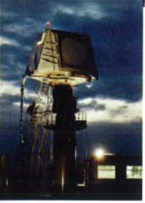
Chapter 3 then gives a detailed introduction to the MESAR experimental multi-function
radar, to which much of this research will be applicable. MESAR is an advanced
experimental active phased array radar which has been developed collaboratively
between the Defence Evaluation and Research Agency and British Aerospace Defence
Systems (formerly Siemens Plessey Systems) since the early 1980s. The fully functional
radar was completed in early 1993, and has been used as a test-bed for experimentation
and demonstration of techniques. This chapter indicates the performance and capability
I Introduction
of a current, state of the art multi-function radar system, and gives a background to what
has been achieved already and what flexibility remains to be harnessed.
Chapter 4 investigates the impact of two digital beamforming techniques that will be
available in the future version of the MESAR radar, MESAR II. These are the
generation of variable beamwidth, and simultaneous multiple receive beam processing.
Novel methods are developed to allow an accurate analysis of the search time- budget
for a sectored surveillance volume, for both static and rotating array multi-function
radars. Two important conclusions are drawn out from the analysis made. Firstly it is
shown that the traditional view that 3 or 4 fixed array faces is the best antenna
configuration for a multi-function radar is not correct, and that rotating array systems
can perform the surveillance function a great deal more efficiently. Secondly, it is
demonstrated that the inherent compromise in beamwidth normally associated with a
multi-function radar does not necessarily hold with a simultaneous multiple receive
beam system. The search and track beamwidth could be de- coupled and each be
optimised to their task.
Chapter
5
addresses the topic of resource management and task scheduling of amulti-function radar. It covers the objectives of resource management and task scheduling in
multi-function radar, and presents figures of merit by which a scheduling and resource
management system may be judged. It also covers the complications that arise with
rotation of the array antenna, and presents a novel algorithm that copes with these
complications. Models are presented that have been developed for both static and
rotating array multi-function radars based around a task scheduler centered architecture,
which are used to evaluate both scheduler performance against the proposed objectives.
Chapter 6 presents a detailed investigation of a static and rotating array adaptive
tracking of manoeuvring targets. The objective of the work presented is to develop an
effective tracking strategy against manoeuvring targets that is efficient in its use of the
multi-function radar's resources. Models of both static and rotating array adaptive
trackers are developed, and then applied through Monte Carlo simulation to determine
an efficient signal to noise ratio to aim for when updating tracks. It is shown that
multiple beam track updates are necessary to enable efficient and robust tracking, and a
strategy for multiple beam update tracking is suggested. The impact of tracking using a
I introduction
Chapter 7 gathers together the most significant conclusions of chapters 4, 5 and 6, and presents a short assessment of a narrow beamwidth, rotating array multi-function radar
which utilises simultaneous multiple beam processing. Its radar time-budget resources
and detection performance are compared to a static array system, similar to the current
MESAR system. The viability of the multiple beam rotating array system is
demonstrated, and it is shown to have to have very favourable characteristics.
Finally chapter 8 presents the conclusions of the work so far, and suggest further work
that would be beneficial in the area of this
g/vc.
1.4 Novel Aspects
The novel aspects of this thesis are contained in chapters 4, 5, 6 and 7, and are summarised here. In chapter 4, a new analysis of multi-function radars with different
array antenna configurations and of simultaneous multiple beam processing has been
made, utilising a novel method for accurate estimation of the surveillance resource
requirements. Chapter 5 proposes a set of objectives for the resource management of a rotating array radar, which may be used to judge the effectiveness of future strategies.
The existing MESAR scheduling algorithms are validated against these objectives. A
novel rotating array scheduler has been developed and assessed, which takes advantage
of a previously unrecognised ability of rotating array multi-function radar systems.
In chapter 6 a novel multiple beam, rotating array adaptive tracker is developed. This,
along with a static array tracker based on that used in the MESAR radar, are applied in a
Monte Carlo simulation to determine the most efficient operating parameters. The result
is a comparison of the tracking performance and efficiency of static and rotating array
multi-function radars. The capability of such systems operating with narrower
beamwidths than those currently used is demonstrated against the benchmark tracking
problem developed by Blair and Watson [Blair et al, 1994].
Chapter 7 demonstrates the viability of a narrow beamwidth multi-function radar
system, and the benefits such a system would give.
2 AN OVERVIEW OF MULTI-FUNCTION RADAR
2.1 Background
This chapter gives an introduction to some of the topics pertinent to Multi-function
radar. The functions of a multi-function radar for naval air defence are described in
section 2.2 to give a short background and a 'time-line' of a multi-function radar's
operation from surveillance through to missile interception.
Section 2.3 then gives a brief introduction to some of the underlying theory of radar,
phased arrays and multi-function radar, which is relevant to this thesis. Finally, in
sections 2.4 and
2.5,
the benefits and drawbacks of using a multi-function radar ratherthan several specialised radars are discussed.
The multi-function radar is equivalent to a suite of radars, employed for some
application such as air defence. To fulfil its purpose it performs several different
functions which previously would have been undertaken by many different, dedicated
radars. The exact functions that are undertaken are obviously dependent upon the
application, but at least, the multi-function radar will provide search coverage and
concurrent tracking of multiple targets.
The multi-function radar utilises one or more phased array antennas to give one or more
electronically steerable beams, in azimuth, elevation or both. These beams are
multiplexed between the different tasks in different directions under automatic digital
control, so that the total radar time is shared amongst the functions.
At its simplest level a multi-function radar consists of the following:
i. a phased array antenna, (including the associated beamforming and
microwave transmitting and receiving hardware)
ii. signal processing
iii. radar control computer
2 An Overview of Multifunction Radar
It is the coupling of an electronically steerable beam, adaptive waveform generation and
signal processing, with real time automatic computer control that gives the
multi-function radar such power.
Many different types of antennas are utilised in multi-function radars. The antenna
normally consists of one or more planar phased arrays, although cylindrical or spherical
arrays have been used. It may be mechanically rotated or use fixed or positioned arrays,
relying solely on electronic scanning to give the volume coverage.
It is essential to realise at the outset the importance that time plays in a multi-function
radar. The multi-function radar is trying to do the job of many radars, each of which
could dedicate all of its radar time to its own task whether it be short range surveillance
or tracking for example. For this reason it is imperative that the multi-function radar's
time is not wasted but is distributed as efficiently as is possible. Barton, [Barton, (1988)]
recognises this, and gives it as the second of two critical design factors in multi-function
radar;
. Choice of radar frequency, high enough to provide the narrow tracking beam, and low enough to permit rejection of clutter during volume search modes.
Budgeting of radar time, to provide the dwell times necessary for clutter rejection in both search and tracking modes.
Billam [Billam, 1997a] discusses the issue of radar time in multi-function radar
specifically in a recent paper. It is one of the dominant factors in the system design of a
multi-function radar, and thus any techniques that are efficient with radar time are of
prime importance.
2.2 Multi-function radar functions
The functions that a multi-function radar must undertake are specific to its application.
Multi-function radars are utilised in land, sea and air based platforms. To date they are
primarily used for military applications due to the high costs. A ship-borne or
land-based multi-function radar may take over the functions of surface search, short, medium,
and long range search, multiple target tracking, weapon control and aircraft control. An
airborne multi-function radar may also take over the functions of navigation or terrain
2 An Overview of Mull, unction Radar
mapping/avoidance.
The primary application of this research study is naval air defence; thus this will be used
as an example here, and often inherently assumed throughout the rest of the thesis.
Nevertheless, research presented is often still pertinent to land and air based
multi-function radar.
Figure 2-1 below shows the functions that a multi-function radar performing naval air
defence may undertake. The main functions are surveillance, tracking and missile
guidance. A summary of these functions is given in sections 2.2.1 to 2.2.4 below. Other
functions may well be needed, such as target recognition with specific requirements
such as the need for long radar waveforms or very precise scheduling.
(FIRE CONThOL (MultIple chaIm.i)
Tt'J
Hh P hdcoo,e TeccinSoarthlTrack Gadaoco Heacng
aIat0fl Raped Conn
OO Search SO fl ___________
Hh Speed HonZon
EVEILAN
Figure 2-1 Functions of a multi-function radar Jhr naval air defence
2.2.1 Search
The aim of the multi-function radar during search, is to survey a given volume of space
within a given frame time and with a given detection performance, set by the operational
requirement. It must do this with the lowest number of false alarms possible.
Additionally, if the search function is being used for track while scan purposes,
requirements in the positional accuracy of surveillance detections may be included.
In practice this requirement is often very difficult to achieve due to restrictions on the
time-budget available to undertake the search function. Various strategies may be
adopted with the aim of using the radar time optimally. This is discussed later in section
2.3.3.1. To minimise the radar time-budget for surveillance, the search volume will
almost certainly be divided into several sectors, with the waveforms and frame times for
2 An Overview of Mu1tfunction Radar
2.2.2 Plot confirmation
A significant advantage of the multi-function radar is that it can rapidly confirm
detections that are made during the search function, in order to distinguish them from
false alarms due to thermal noise. This function is termed plot confirmation and is
essential in minimising the reaction time of the multi-function radar.
Generally, a 'look back' is used with a waveform that has similar parameters to the
original surveillance waveform that made the detection, to ensure that the target is
detected again. The interval between the surveillance detection and the look back needs
to be minimised to avoid the target decorrelating and hence not being detected. Typical
look back times are between lOms and lOOms.
Additionally the plot confirmation look back may be used to attempt to rapidly resolve
an ambiguity in range or velocity by modifying the PRF of the waveform.
This technique is only used on detections that do not associate with existing tracks in the
system. On each surveillance detection the radar must measure the position of the
detection and compare this with the expected positions of targets that it is already
holding in track (plot association). If the detection correlates with a predicted target
position, then that information may be used as a plot to update that track. If not then a
look back would be requested.
2.2.3 Track initiation
Upon a successful confirmed detection, track initiation is undertaken to establish a track
of sufficient accuracy (in terms of position and velocity) that it may be handed to the
track maintenance function. The aim of track initiation is to establish a track of a given
accuracy in the shortest time possible.
The combination of the plot confirmation and track initiation functions provides the
earliest reaction times and target threat assessment for weapon system needs. In
comparison to a suite of dedicated radars the delay between initial detection can be
significantly larger. In practice several detections are required from a dedicated
surveillance radar (to fulfil an n out of m criterion) in order to obtain the low false alarm
rates that are required before cueing the tracking radar. This requires several sweeps of
the surveillance antenna, which is likely to take several seconds. The dedicated tracking
radar must then perform a search to acquire the target, since the surveillance radar that
2 An Overview of Multifunction Radar
has cued it has a broader beam. This whole process may be achieved in the quickest
time by a multi-function radar that may direct the beam at will.
2.2.4 Track maintenance
The multi-function radar is capable of undertaking two basic means of tracking;
track-while-scan (TWS) and track-and-scan (TAS). Track-track-while-scan simply feeds plots from
the surveillance function to the track extractor, so that the tracks are updated at the
surveillance rate, as with conventional rotating surveillance radars (although the plots
may not be updated at regular intervals with a multi-function radar, due to the random
nature of the scan). Track-and-scan, sometimes referred to as de-coupled tracking,
updates tracks independently, and at a rate higher than the surveillance rate. This
therefore implies an additional load on the radar time-budget.
In general track-while-scan would only be used against low priority targets, or targets
for which the surveillance update rate would give sufficient accuracy. The majority of
targets of interest to a weapon system are likely to have the potential to manoeuvre or
may be closing rapidly. It is most likely that they will have high update rate or accuracy
requirements, and will therefore be tracked using scan. Thus it is
track-and-scan that is the main consideration of this study.
ARRAY COMMUNICATIONS
RADAR TASK SCHEDULER
4
RADAR CONTROL AND WAVEFORM *
SELECTION
SIGNAL PROCESSING
Jr
PLOT POSITION EXTRACTOR
Jr
TRACK EXTRACTOR
Figure 2-2 The closed ioop multi-function radar tracker
The multi-function radar tracker is a closed ioop, as shown in Figure 2-2. For successful
multi-function radar target tracking the inter-related functions of plot to track
association, track filtering and prediction, and radar assignment must all work
seamlessly. If, for example, an incorrect waveform, or an update interval that is too
long, is chosen on the basis of the tracker output, then the next update will be of poor
2 An Overview of Multifunction Radar
2.2.5 Functional flexibility
The enormous flexibility of the multi-function radar system also allows it to be
reconfigured for several different applications. For example a ship borne multi-function
radar could be configured for medium range air defence as its main role. By changing
the configuration of the search volume, the digital waveforms selected, the digital signal
processing applied, and the control algorithms, the same radar could be applied to long
range air defence, or to ballistic missile defence. This may be incorporated as a simple
software, or menu driven option. Perhaps even more significantly, a major benefit of the
multi-function radar is that it can in principle be rapidly reconfigured for unforeseen
applications and eventualities.
2.3 Underlying theory of multi-function radar
A multi-function radar is a specific, and advanced type of radar. As such the well
understood theory from radar and phased array systems is applicable, but also, as has
been pointed out by Billam ([Billam, 1994]), new theory is developing pertinent purely
to multi-function radar systems. This is exemplified by the two books published on this
subject in recent years purely on multi-function radar system aspects ([Billeter, 1989],
[Sabatini & Tarantino, 19941). In some respects it could be said that the system level
theory of multi-function radar - its application and control - is somewhat behind the
capability that the various technologies involved in a multi-function radar suite can
potentially offer. This may lead to a highly sophisticated and adaptable system being
utilised in an essentially conventional way, simply by virtue that a well developed theory
is not available at the radar design stage.
This section introduces the areas of radar theory and phased array theory relevant to this
study, before giving a background to some of the system aspects of multi-function
radars.
2.3.1 Radar systems
The subject area of radar is vast, and well covered in many texts. Notable introductions
to the subject are given by Barton, Levanon and Skolnik ([Barton, 1988], [Levanon,
1988], [Skolnik, 1981]). The purpose of this section is to give only the broadest account
of a complete radar system, and to present a brief introduction to the techniques and
2 An Overview of Multifunction Radar
equations that are applied within the scope of this study.
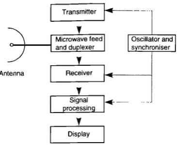
A highly simplified block diagram of a typical radar is shown in Figure 2-3 below.
miUer
crowave feed Oscil exer
Antenna Receiver __________
Signal... processing
y Display
Figure 2-3 A simplified block diagram of a typical radar
A pulsed oscillator feeds a low power RF signal to a transmitter. This signal is
amplified, and possibly modulated. The resultant signal is passed to the antenna for
radiation into space. The antenna directs the transmit energy, in the desired direction. A
target, illuminated by the energy radiated from the antenna, will scatter the energy in all
directions. In general, only a very small amount of the energy will be re-radiated back in
the direction of the antenna.
This small amount of energy, which competes with the energy reflected from other
sources such as the land or sea, or external interference sources, re-enters the antenna.
Received signals are amplified and generally mixed down to a lower frequency in the
receiver before being fed to the signal processor.
The benefits of a highly directional antenna are clear. Firstly, both the energy that is
transmitted, and that which is received, is maximised in the required direction.
Secondly, the interference from other directions is minimised. Lastly, a narrow main
beam formed by a highly directive antenna allows a high angular measurement and
resolution capability.
The signal processor has the job of trying to recover the wanted information, if any,
from the signal it is fed. It must determine, by varied means, whether a target is present
or not in each radar resolution cell. It must extract information about that target, such as
range, echo signal strength, angular position or Doppler velocity, If a target is detected,
s=(PG)(_
a ( Ar I I[2-2]
2 An Overview
of
Multifunction RadarR= [2-1]
2
where R is the slant range of the target c is the speed of propagation
Tr is the time taken by the pulse to travel to the target and return
Barton [Barton, 1988] gives a list of the major problem areas in radar, which, although recognised in the early days of radar, remain only partially solved today.
i. adequate signal to noise ratio in free space
ii. clutter reduction
iii. interference reduction
iv. signal selection
v. measurement accuracy
vi. size, weight, cost and reliability
It is useful to have these problems in mind when considering multi-function radar, since
high performance must be attained in every one of these areas to ensure a good level of
multi-function radar performance.
Often problems in one of these areas will affect the multi-function radar system in more
complicated ways than a conventional radar. For example, poor clutter cancellation will
lead to false detections, and subsequently to false track initiations. This, in turn, will
lead to less radar time being devoted to other functions, such as surveillance, causing a
drop in detection performance.
2.3.1.1 Radar range equation
The range equation is one of the most fundamental equations in radar theory. It allows
the prediction of the range at which a target of given radar cross section may be
detected, given basic information about the radar, the target, and the propagation path of
the radiation through space. One form of this equation allows the determination of the
signal strength given the range of a target: