www.ijiset.com
Finite Element Analysis of Single Point Incremental Deep Drawing
Process for Truncated Pyramidal Cups from AA 1070 Alloy
A. Ravi Teja1, A. Chennakesava Reddy2
1
PG student Department of Mechanical Engineering, JNTUH College of Engineering, Hyderabad – 500 085, Telangana, India
2
Professor, Department of Mechanical Engineering, JNTUH College of Engineering, Hyderabad – 500 085, Telangana, India
Abstract
Simulation of single point incremental deep drawing process for AA 1070 sheet with the help of finite element software and Taguchi experimental techniques. Blank thickness, step depth, tool radius and coefficient of friction are the process parameters for the truncated pyramidal cups. It has been found that the step depth and sheet thickness are highly influential in controlling the formability of cups.
Keywords: AA1070 alloy, single point incremental deep drawing process, blank thickness, tool radius, step depth, coefficient of friction, truncated pyramidal cups.
1. Introduction
Single point incremental forming (SPIF) process is a new process for manufacturing sheet metal parts which is well suited for small batch production or prototyping. In this process a simple ball shaped tool is moved along a predefined path to impose plastic deformation locally in the sheet [1]. The process is very flexible and can be carried out on a computer numerical control (CNC) milling machine. The path of the tool is controlled by a part program generated using computer aided manufacturing (CAM) software. In a series of research on deep drawing process, abundant explorations have been made to fabricate various cups using different materials such as AA1050 alloy [2], AA1070 alloy [3], AA1080 alloy [4], AA1100 alloy [5], AA2014 alloy [6], AA2017 alloy [7], AA2024 alloy [8], AA2219 alloy [9], AA2618 alloy [10], AA3003 alloy [11], AA5052 alloy [12], AA5039 alloy [13], Ti-Al-4V alloy [14], EDD steel [15] and gas cylinder steel [16]. From the literature it is found that the incremental sheet forming is restricted by different parameters: the wall angle, tool diameter, incremental size and the initial sheet thickness [17]. Recently, finite element analysis (FEA) has been a powerful tool to evaluate the final part characteristics [18].
Present work was focussed on the finite element analysis of SPIF process of AA1070 alloy using commercial software ABAQUS. The investigation was to optimize the process parameters such as blank thickness, step depth, coefficient
of friction and tool radius. The design of experiments was carried out using Taguchi technique.
2. Materials and Methods
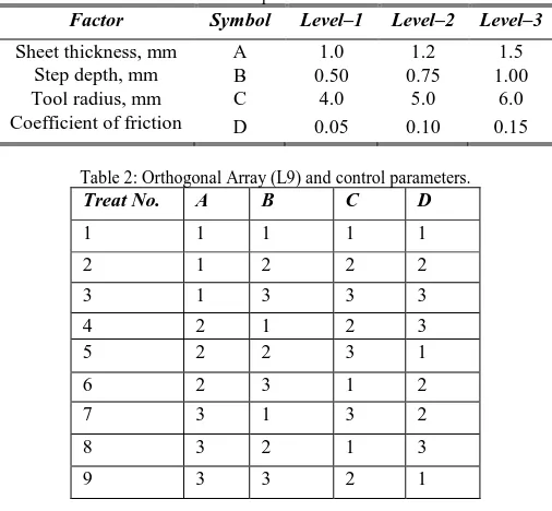
In the present work, ABAQUS (6.14) software code was used for the numerical simulation of SPIF process to fabricate conical cups. The material was AA1070 alloy. The SPIF process parameters were chosen at three levels as summarized in table 1. The orthogonal array (OA), L9 was preferred to carry out experimental and finite element analysis (FEA) as given in table 2.
Table 1: Process parameters and levels
Factor Symbol Level–1 Level–2 Level–3
Sheet thickness, mm A 1.0 1.2 1.5
Step depth, mm B 0.50 0.75 1.00
Tool radius, mm C 4.0 5.0 6.0
Coefficient of friction D 0.05 0.10 0.15
Table 2: Orthogonal Array (L9) and control parameters.
Treat No. A B C D
1 1 1 1 1
2 1 2 2 2
3 1 3 3 3
4 2 1 2 3
5 2 2 3 1
6 2 3 1 2
7 3 1 3 2
8 3 2 1 3
9 3 3 2 1
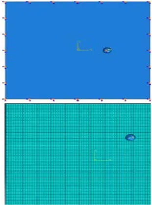
material properties. The tool path geometry was generated using CAM software [20] and imported to the ABAQUS as shown in Fig. 2. The elastic-plastic deformation analysis was carried out for the equivalent stress, strain and strain rates and thickness variation.
Fig. 1 Modeling of sheet and single point tool.
Fig. 2 Profile tool path.
3. Results and Discussion
In the present work, the significance of process parameters should have at least 90% of confidence. Hence, the process parameters which had an absolute Fisher’s ratio larger than 3.4579 were believed to influence the average value for the forming characteristic under null hypothesis. Parameters which had Fisher’s ratio less than 3.457 were believed to have no effect on the average.
3.1 Effect of Process Parameters on Effective Stress
In table 3, the percent contribution indicates that the
parameter A, sheet thickness, all by itself contributes 47.01%. The parameter step depth (B) stands second and its influence is 39.06% on the effective stress. The tool radius (C) has an effect of only 9.26% on the total variation in the effective stress. The coefficient of friction (D) contributes merely 4.67% of the total variation in the effective stress.
Table 3 : ANOVA summary of the effective stress.
Source Sum 1 Sum 2 Sum 3 SS v V F P
A 579.5 625.4 600.4 352.06 1 352.06 46941.33338 47.01
B 588.3 591.1 625.9 292.51 1 292.51 39001.33337 39.06
C 611.9 591.5 601.9 69.36 1 69.36 9248.00001 9.26
D 594.1 602.7 608.5 34.99 1 34.99 4665.33334 4.67
e 0.03 4 0.0075 1.00000 0
T 2373.8 2410.7 2436.7 748.95 8 100
Note: SS is the sum of square, v is the degrees of freedom, V is the variance, F is the Fisher’s ratio, P is the percentage of contribution and T is the sum squares due to total variation.
Fig. 3 Effect of process parameters on von effective stress.
www.ijiset.com
the blank sheet are higher in number than the tensile stresses. The deformation based on compression for the strain less than 2.0 and it is tensile for the strain greater than 2.0. The shear stress developed in the blank sheet is nearly 50% of S11.
Fig. 4 Effect of process parameters on S11.
Fig. 5 Effect of process parameters on S22.
Fig. 6 Effect of process parameters on S12.
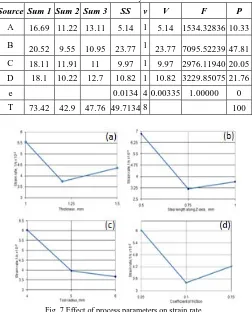
3.2 Effect of Process Parameters on Strain Rate
The relative influences of process parameters on strain rate are summarized in table 4. The percent contribution
indicates that the parameter, step depth (B), all by itself accords 47.81% of the total variation in the strain rate. Coefficient of friction (D) shows an effect of 21.76% in the strain rate. The tool radius (C) commits to one-fifth of total variation in the strain rate (20.05%). The sheet thickness(A) dispenses 10.33% of the total variation in the strain rate.
Table 4 : ANOVA summary of the strain rate
Source Sum 1 Sum 2 Sum 3 SS v V F P
A 16.69 11.22 13.11 5.14 1 5.14 1534.32836 10.33
B 20.52 9.55 10.95 23.77 1 23.77 7095.52239 47.81
C 18.11 11.91 11 9.97 1 9.97 2976.11940 20.05
D 18.1 10.22 12.7 10.82 1 10.82 3229.85075 21.76
e 0.0134 4 0.00335 1.00000 0
T 73.42 42.9 47.76 49.7134 8 100
Fig. 7 Effect of process parameters on strain rate.
The strain rate ratio would almost decrease with an increase in the blank thickness, step depth, tool radius and coefficient of friction as illustrated in Fig. 7. The average maximum strain rate was in the range of 0.046 s-1. The strain rate values indicate the superplastic deforming during the SPIF deep drawing of AA1070 alloy.
3.3 Effect of Process Parameters on Thickness
Reduction
Table 5 : ANOVA summary of the thickness reduction
Source Sum 1 Sum 2 Sum 3 SS v V F P
A 221 233.08 232.533 31.04 1 31.04 16554.66665 22.63
B 235.37 234.75 216.5 76.6 1 76.6 40853.33330 55.85
C 222.23 234.17 230.217 24.64 1 24.64 13141.33332 17.97
D 231.82 228.3 226.5 4.88 1 4.88 2602.66666 3.56
e
-0.0075 4
-0.0018 1.00000 0
T 910.42 930.3 905.75 137.1525 8 100
As seen from Fig. 8, the reduction of thickness increased with increase of blank thickness from 1.0 mm to 1.2 mm and it was constant from 1.2 mm to 1.5 mm (Fig. 8a). The reduction in sheet thickness was constant for step depth from 0.5 mm to 0.75 mm and later on it was decreased (Fig. 8b). Initially, the reduction in sheet thickness was increased with increase of tool radius from 4.0 mm to 5.0 mm and thereafter it decreased slightly (Fig. 8c). As the coefficient of friction increased the reduction in sheet thickness was continuously decreased (Fig. 8d).
Fig.8. Effect of process parameters on thickness reduction.
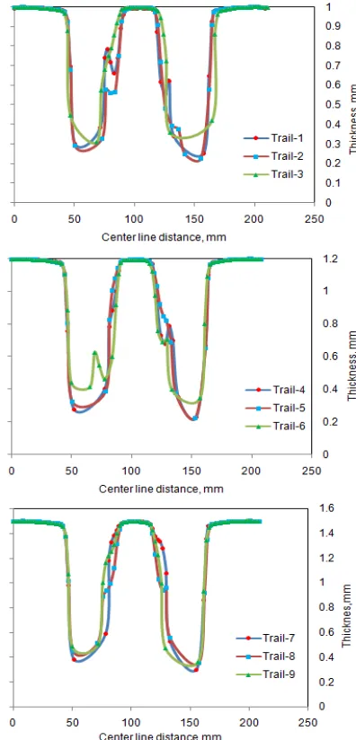
Fig. 9 Location of thickness reduction in the deformed cup.
The variation of thickness was considered at the center-line of the deformed cup as shown in Fig. 9. As observed from Fig. 10, the majority of thickness reduction takes place in the walls of the cup but not in the flange or bottom of the cup. The elements located at the mid regions of the walls are elongated higher than those present at the top and bottom of the cup walls. Below the mid regions of the walls for sheet thickness of 1.0 mm and 1.2 mm, the material built up was inconsistent.
Fig. 10 Effect of process parameters on thickness reduction.
3.4 Formability of SPI Deep Drawing Process
www.ijiset.com
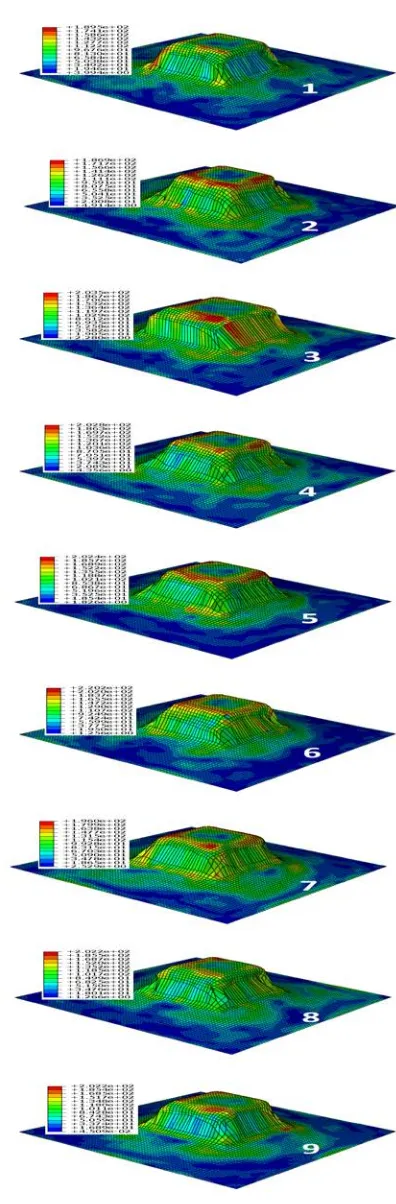
von Mises stresses are, respectively, 189.2 MPa, 186. 5 MPa and 203.5 MPa. For the trials 4, 5 and 6, the von Mises stresses are, respectively, 202.8 MPa, 202. 4 MPa and 220.2 MPa. For the trials 7, 8 and 9, the von Mises stresses are, respectively, 196.0 MPa, 202.2 MPa and 202.2 MPa. The formability of cups for the trials 7, 8 and 9 was excellent as compared to the rest of trials. The safe tensile and compressive strain should be less than 0.2 to prevent the rupture in the cups.
Fig. 11 Forming limit diagrams of trials 1, 2 and 3.
Fig. 12 Forming limit diagrams of trials 4, 5 and 6.
Fig. 13 Forming limit diagrams of trials 7, 8 and 9.
It is observed from Fig. 14 that the high stresses are induced at the bottom corners and along the edges of walls in the deformed cups.
4. Conclusion
In the present work, the finite element analysis and Taguchi techniques are successfully implemented to simulate single point incremental deep drawing process for the AA 1070 sheet. The major parameters, which influences the effective stress, are the sheet thickness and step depth. The strain rate decreases with increase of process parameters chosen in the present work. The thickness reduction is greatly affected by the step depth. The formability of the cups is dominated by the tensile and compression behavior of AA 1070 sheet.
Acknowledgment
The authors wish to thank University Grants Commission (UGC), New Delhi for the support of this work.
References
[1] J. J. Park, Y. H. Kim, "Fundamental studies on the incremental sheet metal forming technique," Journal of Materials Processing Technology, Vol. 140, 2003, pp. 447– 453.
[2] A. C. Reddy, "Homogenization and Parametric Consequence of Warm Deep Drawing Process for 1050A Aluminum Alloy," Validation through FEA, International Journal of Science and Research, Vol. 4, No. 4, 2015, pp. 2034-2042,.
[3] K. Chandini and A. C. Reddy, "Finite Element Analysis of Warm Deep Drawing Process for Pyramidal Cup of AA1070 Aluminum Alloy," International Journal of Advanced Research, Vol. 3, No. 6, 2015, pp. 1325-1334. [4] B. Yamuna and A. C. Reddy, "Finite Element Analysis of
Warm Deep Drawing Process for Conical Cup of AA1080 Aluminum Alloy," International Journal of Advanced Research, Vol. 3, No.6, 2015, pp. 1309-1317.
[5] T. Srinivas and A. C. Reddy, "Finite Element Analysis of Warm Deep Drawing Process for Rectangular Cup of AA1100 Aluminum Alloy," International Journal of Advanced Research, Vol. 3, No. 6, 2015, pp. 1383-1391. [6] A. C. Reddy, "Parametric Optimization of Warm Deep
Drawing Process of 2014T6 Aluminum Alloy Using FEA," International Journal of Scientific & Engineering Research, Vol. 6, No. 5, 2015, pp.1016-1024.
[7] A. C. Reddy, "Finite Element Analysis of Warm Deep Drawing Process for 2017T4 Aluminum Alloy: Parametric Significance Using Taguchi Technique," International Journal of Advanced Research, Vol. 3, No. 5, 2015, pp. 1247-1255.
[8] A. C. Reddy, "Parametric Significance of Warm Drawing Process for 2024T4 Aluminum Alloy through FEA," International Journal of Science and Research, Vol. 4, No. 5, 2015, pp. 2345-2351.
[9] A. C. Reddy, "Formability of High Temperature and High Strain Rate Superplastic Deep Drawing Process for AA2219 Cylindrical Cups," International Journal of Advanced Research, Vol. 3, No. 10, 2015, pp. 1016-1024.
[10]A. C. Reddy, "High temperature and high strain rate superplastic deep drawing process for AA2618 alloy cylindrical cups," International Journal of Scientific Engineering and Applied Science, Vol. 2, No. 2, 2016, pp. 35-41.
[11]A. C. Reddy, "Practicability of High Temperature and High Strain Rate Superplastic Deep Drawing Process for AA3003 Alloy Cylindrical Cups," International Journal of Engineering Inventions, Vol. 5, No. 3, 2016, pp. 16-23. [12]A. C. Reddy, "Suitability of High Temperature and High
Strain Rate Superplastic Deep Drawing Process for AA5052 Alloy," International Journal of Engineering and Advanced Research Technology, Vol. 2, No. 3, 2016, pp. 11-14. [13]A. C. Reddy, "High temperature and high strain rate
superplastic deep drawing process for AA5049 alloy cylindrical cups," International Journal of Engineering Sciences & Research Technology, Vol. 5, No. 2, 2016, pp. 261-268.
[14]A. C. Reddy, "Finite element analysis of reverse superplastic blow forming of Ti-Al-4V alloy for optimized control of thickness variation using ABAQUS," Journal of Manufacturing Engineering, Vol. 1, No. 1, 2016, pp.6-9. [15]A. C. Reddy, T. K. K. Reddy, M. Vidya Sagar,
"Experimental characterization of warm deep drawing process for EDD steel," International Journal of Multidisciplinary Research & Advances in Engineering, Vol. 4, No. 3, 2012, pp.53-62.
[16]A. C .Reddy, "Evaluation of local thinning during cup drawing of gas cylinder steel using isotropic criteria," International Journal of Engineering and Materials Sciences, Vol. 5, No. 2, 2012, pp.71-76.
[17]Y. H. Kim, J. J Park. “Effect of process parameters on formability in incremental forming of sheet metal,” Journal of Materials Processing Technology, Vol. 130-131, 2002, pp. 42-46.
[18] H. Arfa, R. Bahloul, H.Bel Hadj Salah, "Finite element modelling and experimental investigation of single point incremental forming process of aluminum sheets: Influence of process parameters on punch force monitoring and on mechanical and geometrical quality of parts," IJFO-D-11-00110R1, 2012.
[19]Chennakesava, R. Alavala, “CAD/CAM: Concepts and Applications,” PHI Learning Pvt. Ltd, 2008: