NetScaler 9000 Series
Installation and Configuration Guide - Vol. 1
180 Baytech Drive San Jose, CA 95134
Phone: 408-678-1600, Fax: 408-678-1601 www.netscaler.com
WORK (SUCH AS TRANSLATION, TRANSFORMATION, OR ADAPTATION) WITHOUT THE EXPRESS WRITTEN PERMISSION OF NETSCALER, INC.
ALTHOUGH THE MATERIAL PRESENTED IN THIS DOCUMENT IS BELIEVED TO BE ACCURATE, IT IS PRESENTED WITHOUT WARRANTY OF ANY KIND, EXPRESS OR IMPLIED. USERS MUST TAKE ALL RESPONSIBILITY FOR THE USE OR APPLICATION OF THE PRODUCT(S) DESCRIBED IN THIS MANUAL. NETSCALER, INC. OR ITS SUPPLIERS DO NOT ASSUME ANY LIABILITY THAT MAY OCCUR DUE TO THE USE OR APPLICATION OF THE PRODUCT(S) DESCRIBED IN THIS DOCUMENT. INFORMATION IN THIS DOCUMENT IS SUBJECT TO CHANGE WITHOUT NOTICE. COMPANIES, NAMES, AND DATA USED IN EXAMPLES ARE FICTITIOUS UNLESS OTHERWISE NOTED.
The following information is for FCC compliance of Class A devices: This equipment has been tested and found to comply with the limits for a Class A digital device, pursuant to part 15 of the FCC rules. These limits are designed to provide reasonable protection against harmful interference when the equipment is operated in a commercial environment. This equipment generates, uses, and can radiate radio-frequency energy and, if not installed and used in accordance with the instruction manual, may cause harmful interference to radio communications. Operation of this equipment in a residential area is likely to cause harmful interference, in which case users will be required to correct the interference at their own expense.
Modifying the equipment without NetScaler’s written authorization may result in the equipment no longer complying with FCC requirements for Class A digital devices. In that event, your right to use the equipment may be limited by FCC regulations, and you may be required to correct any interference to radio or television communications at your own expense. You can determine whether your equipment is causing interference by turning it off. If the interference stops, it was probably caused by the NetScaler Request Switch™ 9000 Series equipment. If the NetScaler equipment causes interference, try to correct the interference by using one or more of the following measures:
•Move the NetScaler equipment to one side or the other of your equipment. •Move the NetScaler equipment farther away from your equipment.
•Plug the NetScaler equipment into an outlet on a different circuit from your equipment. (Make sure the NetScaler equipment and your equipment are on circuits controlled by different circuit breakers or fuses.)
Modifications to this product not authorized by NetScaler, Inc., could void the FCC approval and negate your authority to operate the product.
BroadCom is a registered trademark of BroadCom Corporation. Fast Ramp, NetScaler, and NetScaler Request Switch are trademarks of NetScaler, Inc. Linux is a registered trademark of Linus Torvalds. Internet Explorer, Microsoft, PowerPoint, Windows and Windows product names such as Windows NT are trademarks or registered trademarks of the Microsoft Corporation. NetScape is a registered trademark of Netscape Communications Corporation. Red Hat is a trademark of Red Hat, Inc. Sun and Sun Microsystems are registered trademarks of Sun Microsystems, Inc. Other brand and product names may be registered trademarks or trademarks of their respective holders.
Software covered by the following third party copyrights may be included with this product and will also be subject to the software license agreement: Copyright 1998 © Carnegie Mellon University. All rights reserved. Copyright © David L. Mills 1993, 1994. Copyright © 1992, 1993, 1994, 1997 Henry Spencer. Copyright © Jean-loup Gailly and Mark Adler. Copyright © 1999, 2000 by Jef Poskanzer. All rights reserved. Copyright © Markus Friedl, Theo de Raadt, Niels Provos, Dug Song, Aaron Campbell, Damien Miller, Kevin Steves. All rights reserved. Copyright © 1982, 1985, 1986, 1988-1991, 1993 Regents of the University of California. All rights reserved. Copyright © 1995 Tatu Ylonen, Espoo, Finland. All rights reserved. Copyright © UNIX System Laboratories, Inc. Copyright © 2001 Mark R V Murray. Copyright 1995-1998 © Eric Young. Copyright © 1995,1996,1997,1998. Lars Fenneberg. Copyright © 1992. Livingston Enterprises, Inc. Copyright © 1992, 1993, 1994, 1995. The Regents of the University of Michigan and Merit Network, Inc. Copyright © 1991-2, RSA Data Security, Inc. Created 1991. Copyright © 1998 Juniper Networks, Inc. All rights reserved. Copyright © 2001, 2002 Networks Associates Technology, Inc. All rights reserved. Copyright (c) 2002 Networks Associates Technology, Inc. Copyright 1999-2001© The Open LDAP Foundation. All Rights Reserved. Copyright © 1999 Andrzej Bialecki. All rights reserved. Copyright © 2000 The Apache Software Foundation. All rights reserved. Copyright (C) 2001-2003 Robert A. van Engelen, Genivia inc. All Rights Reserved.
Contents
Chapter- 1
Introduction to the NetScaler 9000 Series. . . 1-1
1.1 - Who Should Use This Book. . . 1-1
1.2 - How to Use The NetScaler 9000 Series Guides . . . 1-2
1.3 - Documentation Conventions . . . 1-5
1.4 - The NetScaler 9000 Series . . . 1-5
1.5 - Features at a Glance. . . 1-10
1.6 - Technical Support and Resources. . . 1-17
Chapter- 2
Installation, Configuration and Management . . . 2-1
2.1 - System Models . . . 2-1
2.2 - LCD Monitor in NetScaler 9000 System . . . 2-4
2.4 - Configuring the NetScaler 9000 System . . . 2-25
2.5 - Maintaining the NetScaler 9000 System . . . 2-43
2.6 - Managing the NetScaler 9000 System . . . 2-44
2.7 - Path MTU Discovery . . . 2-78
2.8 - Understanding NetScaler License Keys . . . 2-81
2.9 - Autodetect Service. . . 2-84
Chapter- 3
High Availability . . . 3-1
3.1 - Overview . . . 3-1
3.2 - Considerations for High Availability Setup. . . 3-3
3.3 - Configuring two NetScaler 9000 systems in High Availability Mode . . 3-6
3.4 - Changing to a High Availability Configuration . . . 3-10
3.5 - Verifying Configuration Propagation . . . 3-13
3.6 - Forced Synchronization. . . 3-14
3.7 - Force Failover of the Primary NetScaler 9000 System . . . 3-15
Chapter- 4
NetScaler Statistical Utility . . . 4-1
4.1 - Overview . . . 4-1
4.2 - Accessing NetScaler Dashboard. . . 4-2
4.3 - Understanding Graphs and Legends. . . 4-6
4.4 - Dashboard Components . . . 4-7
4.5 - Monitoring Performance Statistics of Key NetScaler Features . . . 4-17
Appendix- A
Policy Expressions . . . A-1
A.1 - Understanding Expressions . . . A-2
A.1 - Using an expression in a policy definition. . . A-14
Appendix- B
NetScaler API Reference . . . B-1
B.1 - Introducing NetScaler Application Programming Interface . . . B-1
B.2 - Benefits of NetScaler API . . . B-2
B.3 - Hardware and Software Requirements. . . B-2
B.4 - Interface Description. . . B-2
B.5 - NetScaler API Architecture . . . B-3
B.6 - The NSConfig Interface. . . B-4
B.7 - Example: Setting the NetScaler Configuration . . . B-5
B.8 - Example: Querying the NetScaler Configuration. . . B-6
B.9 - The Web Service Definition Language (WSDL) . . . B-8
B.10 - Creating Client Applications using the NSConfig.wsdl File. . . B-9
B.11 - Securing NetScaler API Access . . . B-11
Appendix- C
Chapter 1
Introduction to the NetScaler 9000 Series
Welcome to the NetScaler 9000 Series Installation and Configuration Guide. This guide describes how to install, configure and manage all of the products included in the NetScaler 9000 product line and includes several sample configurations to assist you in planning for system deployment in your own network environment.
Topics included in this chapter are: z Who Should Use This Book
z How to Use The NetScaler 9000 Series Guides z Documentation Conventions
z The NetScaler 9000 Series z Features at a Glance
z Technical Support and Resources
Note:
1. By default, this guide refers to the product as the NetScaler 9000 system.
2. When referring to the Secure Application Accelerator this guide uses specific model numbers: 9050, 9100, or 9500.
3. When referring to the Secure Application Gateway, this guide uses specific model numbers: 9200, 9600 or 9900.
4. When referring to the Secure Application Switch this guide uses specific model numbers: 9400, 9800 or 9950.
1.1 Who Should Use This Book
The Installation and Configuration Guide is intended for developers, test engineers, system administrators or others who install and configure NetScaler 9000 systems into their network infrastructures.
Knowledge of the software and services running on web servers is needed to configure the system appropriately. Basic knowledge of networking and web technologies is assumed.
1.2 How to Use The NetScaler 9000 Series Guides
To help you use the NetScaler 9000 system and it’s various features, this documentation set is contained in two volumes. These volumes are organized as follows.
1.2.1 Volume 1
This Volume covers the general use and management features of the NetScaler 9000 Series system. Refer to this guide for instruction on installation, management, administration, and all non-feature specific tasks. z Chapter 1, Introduction to the NetScaler 9000 Series: This chapter
describes the basic features and benefits of the NetScaler 9000 system. It also provides a brief description of the key features that can be configured on the NetScaler 9000 system.
z Chapter 2, Installation, Configuration and Management: This chapter describes how to install, configure and manage the NetScaler 9000 system.
z Chapter 3, High Availability: This chapter describes how to install and configure the NetScaler 9000 system in the High Availability mode. z Chapter 4, NetScaler Statistical Utility: This chapter introduces you to
the NetScaler Statistical Utility (also referred as the NetScaler
Dashboard). It explains the various components of this graphical utility and also the steps to monitor the NetScaler 9000 system’s performance using the Dashboard utility.
z Appendix A, Policy Expressions: This appendix provides an overview on constructing NetScaler Policy Expressions.
z Appendix B, NetScaler API Reference: This chapter provides
information on the NetScaler Application Programming Interface (API) and detailed instructions on how to use this XML API to implement customized client applications.
z Appendix C, Warning and Safety Messages: This appendix provides various warning messages and their description.
1.2.2 Volume 2
In this Volume, you will find the documentation for the specific features available on the NetScaler 9000 Series system.
z Chapter 1, Load Balancing: This chapter describes the steps to configure and manage various Load Balancing (LB) feature in the NetScaler 9000 system.
z Chapter 2, Firewall Load Balancing: This chapter describes the steps to configure and manage the the Firewall Load Balancing feature in the NetScaler 9000 system.
z Chapter 3, Global Server Load Balancing: This chapter describes the steps to configure and manage the GSLB feature in the NetScaler 9000 system.
z Chapter 4, Content Switching: This chapter describes the steps to configure and manage the Content Switching (CS) feature in the NetScaler 9000 system.
z Chapter 5, Cache Redirection: This chapter describes the steps to configure and manage the Cache Redirection (CRD) feature in the NetScaler 9000 system.
z Chapter 6, Configuring Integrated Caching: This chapter describes the steps to configure and manage the Integrated Cache feature.
z Chapter 7, Secure Sockets Layer (SSL) Acceleration: This chapter describes the steps to configure and manage the Secure Sockets Layer (SSL) Acceleration feature in the NetScaler 9000 system.
z Chapter 8, Secure Virtual Private Network (SSL VPN): This chapter describes the steps to configure and manage the SSL VPN feature. z Chapter 9, Web Server Logging: This chapter describes the steps to
configure and manage the Web Server Logging feature in the NetScaler 9000 system.
z Chapter 10, Performance: This chapter describes the steps to configure and tune the various performance features in the NetScaler 9000 system, such as Compression, Connection Keep-alive/server off load, Client Keep Alive and TCP buffering.
z Chapter 11, Protection: This chapter describes the steps to configure and manage the various protection features in the NetScaler 9000 system, such as, Surge Protection, Priority Queuing, DoS Protection, Content
z Chapter 12, Sure Connect: This chapter describes the steps to configure and manage the SureConnect feature in the NetScaler 9000 system. z Chapter 13, Advanced Network Configurations: This chapter
describes how to configure advanced features such as, Layer 2 Mode, Use Source IP addresses (USIP), MAC-based Forwarding and VLANs support in the NetScaler 9000 system.
z Appendix A, Optimizing Web Servers: This appendix provides the steps to optimize performance for various web servers.
z Appendix B, Converting Certificates and Keys: This appendix provides steps to convert certificate and key format using the OpenSSL tool.
z Appendix C, Fine Tuning Built-in Integrated Cache Behavior: This appendix provides information on how to fine tune the built-in cachability behavior.
z Appendix D, Built-in Behavior of Integrated Cache: This appendix provides cache policies and the corresponding built-in cachability behavior.
1.3 Documentation Conventions
1.4 The NetScaler 9000 Series
The NetScaler 9000 Series of secure application networking systems is designed to protect and optimize the delivery of applications over the Internet and private networks. To achieve this, it combines application-level security,
CONVENTION ALERTS YOU TO:
Command This typeface represents a command that you must type using the exact upper/lower case characters shown.
After every command typed into the NetScaler 9000 Command Line Interface (CLI) press the Return or Enter key on your keyboard.
Command argument This typeface represents a command argument.
Screen text Text with this typeface represents information on a screen, as well as the names of directories, files and commands.
<Key name>+<Key name> Keyboard key names appear within angle brackets. A plus sign appears between keys that you must press simultaneously. Text in italics Italic type emphasizes text or indicates new terms.
Initial Capital Letters Names of windows, dialogs, tabs, menus, icons, buttons and other user interface elements start with capital letters.
ICON NOTICE TYPE ALERTS YOU TO:
NOTE Information note Important additional information
CAUTION Caution Risk of personal injury, system damage or data loss
9000 Series is comprised of three products: the Secure Application
Accelerator (9050/9100/9500), the Secure Application Gateway (9200/9600/ 9900) and the Secure Application Switch (9400/9800/9950).
Each of these solutions is available in Fast Ethernet and gigabit configurations and can be integrated into any environment as a complement to existing load balancers, servers, caches and firewalls. The system requires no additional client or server side software and is easily deployed via the system's web-based GUI and CLI configuration utilities.
Refer to Secure Application Accelerator, Secure Application Gateway and Secure Application Switch in this chapter for a summary of various product models and their key features.
Note: The Secure Application Gateway and Secure Application Switch are also available for non-SSL environments. These products are denoted with a “-N” appended to the model number.
As a complement to the application networking features included in each of the products of the NetScaler 9000 Series, each system can be easily upgraded to support the following additional product options: Proximity-based GSLB and Application Caching.
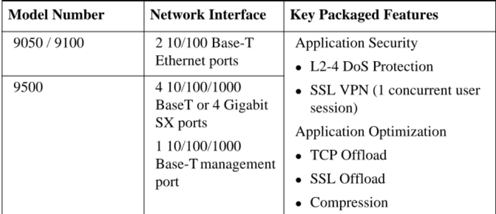
1.4.1 Secure Application Accelerator - Models 9050, 9100 and
9500
The NetScaler Secure Application Accelerator is an entry-level solution that integrates secure remote access with application protection and optimization into a unified platform for secure application delivery. The Secure
Application Accelerator can be deployed to enable client-less secure remote access via SSL VPN technology, and can serve as a security and optimization appliance to encrypt, protect and accelerate application delivery.
Table 1-1 Secure Application Accelerator product line.
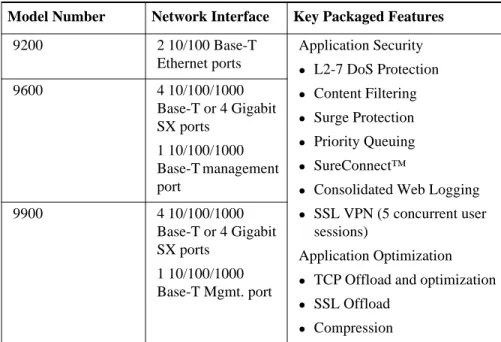
1.4.2 Secure Application Gateway - Models 9200, 9600 and
9900
NetScaler's Secure Application Gateway applies NetScaler's patented Request SwitchingTM technology to provide robust web application security, protection
and optimization. The system is typically deployed as a complement to existing network architectures and can be used to instantly encrypt application data, continuously serve users, and reduce the total cost of operations, all without diminishing the user experience.
Model Number Network Interface Key Packaged Features
9050 / 9100 2 10/100 Base-T Ethernet ports Application Security z L2-4 DoS Protection z SSL VPN (1 concurrent user session) Application Optimization z TCP Offload z SSL Offload z Compression 9500 4 10/100/1000 BaseT or 4 Gigabit SX ports 1 10/100/1000 Base-T management port
Table 1-2 Secure Application Gateway product line:
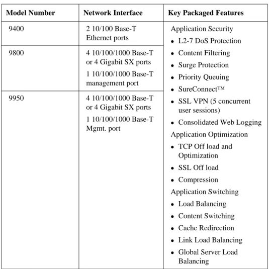
1.4.3 Secure Application Switch - Models 9400, 9800 and
9950
NetScaler’s Secure Application Switch augments the functionality of its Secure Application Gateway to provide fine-grain traffic management - uniquely combining application-level security, optimization, and layer 4-7 switching into a uniform platform. The system is typically deployed as a fully integrated traffic management system, in-line with traffic, to enable
enterprises, e-businesses and service providers to ensure the cost effective, continuous, secure delivery of their business critical applications.
Model Number Network Interface Key Packaged Features
9200 2 10/100 Base-T Ethernet ports Application Security z L2-7 DoS Protection z Content Filtering z Surge Protection z Priority Queuing z SureConnect™
z Consolidated Web Logging z SSL VPN (5 concurrent user
sessions)
Application Optimization z TCP Offload and optimization z SSL Offload z Compression 9600 4 10/100/1000 Base-T or 4 Gigabit SX ports 1 10/100/1000 Base-T management port 9900 4 10/100/1000 Base-T or 4 Gigabit SX ports 1 10/100/1000 Base-T Mgmt. port
Table 1-3 Secure Application Switch product line
1.4.4 Proximity-based GSLB
With this license enabled, the NetScaler system can be configured to make its GSLB decision based on the proximity of the client browser's local DNS server (LDNS) to the destination site. Proximity can be determined
dynamically (i.e. based on the current network status) or statically (based on the geographic location of the client and the sites, as defined on the system).
1.4.5 Application Caching Option
The Application Caching Option for the NetScaler 9000 Series enables
Model Number Network Interface Key Packaged Features
9400 2 10/100 Base-T Ethernet ports Application Security z L2-7 DoS Protection z Content Filtering z Surge Protection z Priority Queuing z SureConnect™ z SSL VPN (5 concurrent user sessions)
z Consolidated Web Logging Application Optimization z TCP Off load and
Optimization z SSL Off load z Compression Application Switching z Load Balancing z Content Switching z Cache Redirection z Link Load Balancing z Global Server Load
Balancing 9800 4 10/100/1000 Base-T or 4 Gigabit SX ports 1 10/100/1000 Base-T management port 9950 4 10/100/1000 Base-T or 4 Gigabit SX ports 1 10/100/1000 Base-T Mgmt. port
performance through the integration of in-memory static and dynamic caching.
1.4.6 Secure Remote Access User Packs
For those businesses that wish to increase the capacity of the Secure Remote Access (SSL VPN) feature in the NetScaler 9000 Series, additional user packs are available as a means of boosting the number of concurrent user sessions supported. By default, the Secure Application Accelerator supports one concurrent user while both the Secure Application Gateway and the Secure Application Switch support five concurrent user sessions, at no additional charges.
1.5 Features at a Glance
1.5.1 Application Intelligent Architecture
Based on NetScaler’s Request Switching™ technology, the NetScaler 9000 system improves the throughput and scalability of application infrastructure by de-coupling the flow of application requests and responses from the underlying transport -- offloading transport processing from servers and freeing valuable CPU cycles. The NetScaler 9000 system then makes optimal use of transport protocols and resources – regulating the flow of requests, keeping long-lived TCP connections and multiplexing application level requests across them – maximizing efficiency even when all of the content is compressed or secured. By leveraging this unique ability to analyze requests and responses, the NetScaler 9000 system can identify and defeat Denial of Service attacks and intrusion attempts, recognize legitimate traffic and boost it in priority to ensure optimal end-user response times.
Request Switching includes the following traffic management techniques: z Offloads transport processing from servers and caches
z Analyzes and optimizes every server response
z Provides adaptive regulation of request flow without transaction loss z Keeps client TCP connections alive to speed response times
z Multiplexes and de-multiplexes application level requests to maximize server efficiency
1.5.2 Application Security Features
The Product Name (short) system includes the following traffic security features:
z SSL Off load and Acceleration
z Secure Remote Access (via SSL VPN)
z Distributed Denial of Service Attack (DDoS) Defense z Content Filtering
z Surge Protection z Priority Queuing
z SureConnect™
1.5.2.1 SSL Off Load and Acceleration
SSL can place a heavy burden on an application's performance and because of encryption, can render many optimization measures ineffective. NetScaler has incorporated high performance SSL acceleration as a core part of its solution, transparently offloading the CPU-intensive SSL encryption/ decryption from local web servers and freeing server resources to service other content requests. All of the benefits of NetScaler's Request Switching technology can be applied to SSL traffic to ensure the secure delivery of web applications without degrading end-user performance.
1.5.2.2 Secure Remote Access
NetScaler’s Secure Remote Access capabilities allow enterprises to provide their employees, partners and customers with instant access to all authorized applications, files or data from a standard Web browser. By using SSL as the underlying protocol, it requires no incremental client software and no changes to servers or LANs.
In addition to providing an internal LDAP directory, the AAA module of this SSL VPN integrates with other enterprise directories such as RADIUS, Microsoft Active Directory and other external LDAP servers.
1.5.2.3 Distributed Denial of Service Attack (DDoS) Defense
The NetScaler 9000 Series product line takes network security to a new level by intelligently stopping malicious attacks before they reach the servers
system identifies legitimate clients and elevates their priority, leaving suspect clients unable to consume resources at a rate that would otherwise cripple a site.
The NetScaler 9000 system provides application-level protection from other malicious attacks including SYN flood attacks, pipeline, teardop, land, fraggle, and zombie connection attacks. The NetScaler 9000 system aggressively defends against these types of attacks by preventing the allocation of server resources for these connections. This insulates servers from the overwhelming flood of packets associated with these events.The NetScaler 9000 system also protects network resources from ICMP based attacks by using a variety of intelligent mechanisms such as ICMP rate limiting and aggressive ICMP packet inspection.
The NetScaler 9000 system also performs strong IP reassembly, drops a variety of suspicious and malformed packets, and applies Access Control Lists (ACLs) to site traffic for further protection.
1.5.2.4 Content Filtering
Content filtering provides protection from malicious attacks for web sites at the layer 7 level. The NetScaler 9000 system inspects every incoming request according to user-configured rules, which are based on HTTP headers. The NetScaler 9000 system then performs the corresponding action to each rule as configured by the user. Actions may include resetting the connection,
dropping the requests or sending an error message. This allows the system to screen unwanted requests from the protected server and reduce the exposure of the server to potential attacks.
The NetScaler 9000 system's content filtering feature can also be used to shield against intrusion attempts by analyzing HTTP GET and POST requests and filtering out known bad signatures. This mechanism can be used to defend against HTTP-based attacks such as variants of Nimda and Code Red virus. 1.5.2.5 Surge Protection
During peak traffic periods, the NetScaler 9000 system maintains the capacity of a server or cache by regulating the flow of user requests to servers and controlling the number of users that can simultaneously access them. By controlling the rate at which connections are established, the NetScaler 9000 system blocks the surge from being passed to the server and prevents the site from becoming overloaded. User requests that arrive after the server has reached its configured capacity are queued at the NetScaler 9000 until
resources become available. Because the surge of traffic has not been passed to the server, the server resources are preserved assuring all users of a better and more consistent experience.
1.5.2.6 Priority Queuing
When a site is in a surge condition and clients are contending for access to server resources, the NetScaler 9000 system can prioritize user request to ensure that the most important traffic is serviced first. Priority can be established based on requested URLs, cookies or a variety of other factors. The NetScaler 9000 system places requests in a three-tier queuing system based on their configured priority, enabling business-critical transactions to flow smoothly even if unexpected surges or site attacks occur. Priority queuing enables continuous delivery of the most important requests, even when a site is under attack or overloaded.
1.5.2.7 SureConnect™
SureConnect ensures application responsiveness even when servers are working at capacity or applications are experiencing processing delays. By providing real-time estimates of Internet response times, interactive priority queuing, and guaranteed content delivery, SureConnect can dramatically improve the real and perceived availability of a site by eliminating the gap between your customer's expectations and their browsing experience.
1.5.3 Application Optimization Features
The NetScaler 9000 system includes the following traffic optimization features: z Compression z TCP Off Load z Client Keep-alive z TCP Buffering z Consolidated Logging z Application Caching z TCP Compression
1.5.3.1 Compression
The NetScaler 9000 system provides transparent compression for HTML and text files. The typical 4:1 compression yields up to 50% reduction in
bandwidth requirements out of the data center. This also results in
significantly improved end-user response time by reducing the amount of data that must be delivered to the browser.
1.5.3.2 TCP Offload
To optimize server throughput and improve response times, the NetScaler 9000 system eliminates server-processing bottlenecks by offloading the TCP connection burden from servers and caches and by enabling long-lived persistent connections across the Internet. This significantly reduces the connection burden on servers and accelerates static, dynamic and interactive content.
1.5.3.3 Client Keep-alive
The NetScaler 9000 system further reduces WAN latency by maintaining persistent connections with the client. Typically, a server with Keep-alive disabled, will close a connection as soon as it has delivered an object. This means a client must open and close many connections to download a
complete page. The NetScaler 9000 system keeps the connection open to the client and then switches new requests onto reusable connections to the server, thus eliminating much of the overhead and delay that the client would experience.
When the server closes the connection, the NetScaler 9000 system keeps the client-side connection (between the client and the NetScaler 9000) open. This allows multiple client requests to be serviced on a single client connection. In the absence of this feature, a client would have to open a new connection for every request to the server. Instead, client keep-alive saves packet round trips associated with connection establishment and closure, reducing the time to complete each transaction.
1.5.3.4 TCP Buffering
The NetScaler 9000 system also allows significant scaling of server
infrastructure and improves application response times in connection-limited, higher packet loss situations by treating all clients as if they were connected at LAN speeds. This is made possible by buffering data from the server onto the NetScaler 9000 system, relieving the server from slow clients and quickly
freeing up resources for new requests. This also permits the NetScaler 9000 system to optimize the TCP parameters for each of these clients and fully manage any retransmissions of dropped packets.
1.5.3.5 Consolidated Web Logging
The NetScaler 9000 system's web server logging feature offloads the logging function from a server or cache to central location. When configured for consolidated web server logging, the NetScaler 9000 system tracks client activity on all of the web servers or virtual web servers to which it is
connected. It can record client activity in a single file or in separate log files. The NetScaler 9000 system supports three different log file formats for displaying data in the log files: W3C Extended log file format, NCSA Common log file format or Custom log format.
1.5.3.6 Application Caching
NetScaler’s Application Caching option helps to optimize the delivery of web content and application data by providing a fast in-memory HTTP/1.1 and HTTP/1.0 compliant web cache for both static and dynamic content. This on-board cache stores the results of incoming application requests even when an incoming request is secured or the data compressed, and then reuses the data to fulfill subsequent requests for the same information. By serving data directly from the on-board cache, the NetScaler 9000 system can eliminate the need to funnel static and dynamic content requests to server infrastructure – offloading servers and reducing page regeneration times.
1.5.4 Application Switching Features
The NetScaler 9000 system includes the following traffic switching features:
z Load Balancing
z Content Switching
z Cache Redirection
z Global Server Load Balancing
z Link Load Balancing
1.5.4.1 Load Balancing
NetScaler’s load balancing feature manages traffic at the request level resulting in more uniform traffic distribution across systems, compared to the
conventional approach of distributing connections among these systems. Load balancing decisions are based on a variety of policies including round robin, least connections, weighted least bandwidth, weighted least packets,
minimum response time and hashing (based on URL, domain source IP or destination IP).
As both TCP and UDP protocols are supported, all HTTP, HTTPS, UDP, DNS, FTP, NNTP, and general firewall traffic can be load balanced. In addition, The NetScaler 9000 system can maintain session persistence based on source IP, cookie, server, group, or SSL session. The NetScaler 9000 system also allows users to apply custom Extended Content Verification (ECV) to servers, caches, firewalls and other infrastructure devices to ensure that these systems are functioning properly and providing the right content to users. The NetScaler 9000 system can also perform other health-monitoring checks via ping, TCP, or HTTP URL.
1.5.4.2 Content Switching
Using a powerful policy engine, the NetScaler 9000 system switches
individual content requests to the server best able to respond. Site rules can be configured based on URL and any combination of HTTP headers. This allows switching decisions to be made based on user and device characteristics such as who the user is, what type of agent they are using, and the content they request.
1.5.4.3 Cache Redirection
Cache redirection manages the flow of traffic to a reverse proxy, transparent, or forward proxy cache farm. It inspects all requests, identifies non-cacheable requests and then sends those requests directly to the origin servers over persistent connections. By intelligently, redirecting non-cacheable requests back to the origin web servers, the NetScaler 9000 system frees cache resources and increases cache hit rates while reducing overall bandwidth consumption and response delays for these HTTP requests.
1.5.4.4 Global Server Load Balancing
The NetScaler 9000 system extends its traffic management capabilities to include distributed Internet sites and global enterprises. Whether installations are spread across multiple network locations or multiple clusters in a single location, the NetScaler 9000 system maintains availability and distributes
traffic across them. Intelligent DNS decisions are then made to prevent users from being sent to a site that is down or overloaded.
1.5.4.5 Link Load Balancing
To further optimize network performance and to ensure business continuity, the NetScaler 9000 system can load balance multiple WAN links and provide link fail over. This link load balancing feature ensures that network
connections remain highly available by applying intelligent traffic control and health checks to efficiently distribute traffic across upstream routers. It identifies the best WAN link to route both incoming and outbound traffic based on policies and network conditions and protects applications against WAN or Internet link failure by providing rapid fault detection and fail over.
1.6 Technical Support and Resources
In addition to the Installation and Configuration Guide and Command Reference, technical assistance is also available in the following locations:
1.6.1 Customer Support
Use the following details for assistance with NetScaler 9000 system products and to contact the NetScaler Customer Support Center.
1.6.2 Release Notes
The release note for the current version of the NetScaler 9000 system is available in the package you received with the product. The release notes,
Website www.netscaler.com Phone USA 1-408-678-1601 Or 1-866-NETSCALER E-mail [email protected]
which contains the latest information for the version of software that is shipped with your system, includes:
z New features and enhancements
Chapter 2
Installation, Configuration and Management
This chapter describes how to install, configure and manage the Product Name (short) system.
Topics included in this chapter are: z System Models
z LCD Monitor in NetScaler 9000 System z Installing the NetScaler 9000 System z Configuring the NetScaler 9000 System z Maintaining the NetScaler 9000 System z Managing the NetScaler 9000 System z Understanding NetScaler License Keys z Autodetect Service
2.1 System Models
The 9400 and 9200 models have identical hardware platforms. In this chapter, we will use NetScaler 9400 to refer to both models unless otherwise noted. Similarly, the 9800 and 9600 have identical hardware platforms. In this chapter, we will use 9800 to refer to both models unless otherwise noted. Note: The 9x00-N variation of each system type has internal hardware
differences but the external appearance is identical.
2.1.1 NetScaler 9400
The NetScaler 9400 is a 1U unit that supports Fast Ethernet and has one GB of memory. Figure 2-1 shows this model.
Figure 2-1 The NetScaler 9400 1U unit that supports Fast Ethernet and has one GB of memory.
Ports
a. Two 10/100Base-T network interfaces (labeled 1/1 and 1/2) b. One auxiliary interface for future use (labeled AUX)
c. Serial Console (9600 baud, 8 bits, 1 stop bit, No parity) LEDs
l The LED labeled 1 on the unit corresponds to the port labeled 1/1. l The LED labeled 2 on the unit corresponds to the port labeled 1/2.
When lit, they indicate the following:
l Green indicates the link is established for the corresponding port. l Yellow indicates that the corresponding port is active (transmitting or
receiving traffic).
2.1.2 NetScaler 9800-SX
The NetScaler 9800-SX is a 2U unit that supports fiber Gigabit Ethernet and has two GB of memory. Figure 2-2 shows this model.
Figure 2-2 The 9800-Secure Application Switch
Ports
a. Four 1000Base-SX network interfaces (labeled 1/1, 1/2, 1/3, and
b. One 10/100/1000Base-T network interface (labeled 0/1) c. Serial Console (9600 baud, 8 bits, 1 stop bit, No parity)
LEDs
When the LEDs on the NetScaler 9800-SX are lit, they indicate the following:
l LED labeled 1000: The corresponding port has been established for
1000Base-SX.
l LED labeled ACT: The corresponding port is active (receiving or
transmitting traffic).
2.1.3 NetScaler 9800-T
The NetScaler 9800-T is a 2U unit that supports copper Gigabit Ethernet and has two GB of memory. Figure 2-3 shows this model.
Figure 2-3 NetScaler 9800-T System
Ports
The NetScaler 9800-T unit has the following ports:
l Four 10/100/1000Base-T network interfaces (labeled 1/1, 1/2, 1/
3, and 1/4)
l One 10/100/1000Base-T network interface (labeled 0/1) l Serial Console (9600 baud, 8 bits, 1 stop bit, No parity)
LEDs
When the LEDs on the NetScaler 9800-T are lit, they indicate the following:
l LED labeled 1000: The corresponding port has been established for
l LED labeled 100: The corresponding port has been established for
100Base-T.
l LED labeled 10: The corresponding port has been established for
10Base-T.
l LED labeled ACT: The corresponding port is active (receiving or
transmitting traffic).
2.2 LCD Monitor in NetScaler 9000 System
The NetScaler 9000 Series products have a Liquid Crystal Display (LCD) on its faceplate. This LCD displays real-time statistics, diagnostic information and active alerts.
Note: By default, the refresh rate of the screen is 3 seconds and this value can be re-configured using the Product Name (short) system LCD Program Options.
Figure 2-4 NetScaler 9000 system 9800-T
2.2.1 Overview
As the dimension of the LCD is limited (two lines of 16 characters), the display information flows through a sequence of screens. Each screen displays a piece of information about some part of a specific NetScaler 9000 system function.
2.2.2 NetScaler 9000 system LCD Back Light
z The NetScaler 9000 system LCD has a neon backlight that starts blinking when there is an active alert. If the display information is more than one screen then it blinks at the beginning of each display screen.
z When the Product Name (short) system shuts down the backlight remains ON exactly for one minute and then automatically turns OFF.
z If the LCD displays OUT OF SERVICE message, this indicates that the Product Name (short) system has been stopped (with or without errors).
2.2.3 Display Information
The display information on the Product Name (short) system LCD can be divided into two categories:
z Special Display Screens: this information is displayed for very specific scenarios.
z Regular Display Screens: this information is displayed when the Product Name (short) system is in active mode.
Note: By default, the refresh rate of the screen is 3 seconds and this value can be reconfigured using the Product Name (short) system’s LCD Program Options. Refer to “NSLCD program options” on page 12 for more information.
2.2.4 Special Display Screens
Power Up screenThis screen is displayed immediately after the Product Name (short) system is switched ON.
Figure 2-5 Power-on display in LCD
2 The second line in the display shows the Product Name (short) system’s power status.
Note:
1. The message on this screen can be customized using a shell command. For more information, refer to “NSLCD program options” on page 12.
2. This Power Up message is displayed until the boot process is successfully completed.
Start Up Screen
This screen is displayed only for few a seconds after the Product Name (short) system successfully starts its operation.
Figure 2-6 Start-up display in LCD
1 The first line in the LCD displays the product name.
2 The second line in the LCD displays the software version and build number.
Out of Service Screen
This screen is displayed when the NetScaler 9000 system stops functioning. The main reasons for the NetScaler 9000 system to stop functioning are:
z Regular NetScaler 9000 system shut down z Operational errors
Figure 2-7 Out of Service display in LCD
1 The first line displays the message.
2 The second line displays the IP address of the NetScaler 9000 system that has stopped.
Note: If the “Out of Service” error message is not displayed on the NetScaler 9000 system LCD, check the NetScaler 9000 system console for more information on why NetScaler 9000 system is not functioning.
2.2.5 Regular Display Screens
Configuration ScreenThe NetScaler 9000 system LCD displays this configuration information as shown in the following figure:
Figure 2-8 Configuration display in LCD
1 The first line displays:
a. The NetScaler 9000 system status as:
z Pri: Indicates that the NetScaler 9000 system box is in
Stand-alone mode or indicates that the NetScaler 9000 system is the Primary node in a High Availability pair.
—Or—
z Sec: Indicates that the NetScaler 9000 system is the Secondary node in a High Availability pair.
b. The system uptime of the NetScaler 9000 unit in the HH:MM format.
c. The NetScaler 9000 system Alert status:
z For a known alert, the alert name is shown in the following figure:
Figure 2-9 LCD displaying Known Alert
z For an unknown alert, a message ‘Alert’ is displayed as shown in the following figure:
Figure 2-10 LCD displaying Unknown Alert
2 The second line displays the IP address of the NetScaler 9000 system. HTTP Statistic Screen
The NetScaler 9000 system LCD displays the HTTP statistics as shown in the following figure:
Figure 2-11 LCD displays HTTP Statistics
1 The first line displays the rate of HTTP GETs per second. 2 The second line displays the rate of HTTP POSTs per second Network Traffic Statistic screen
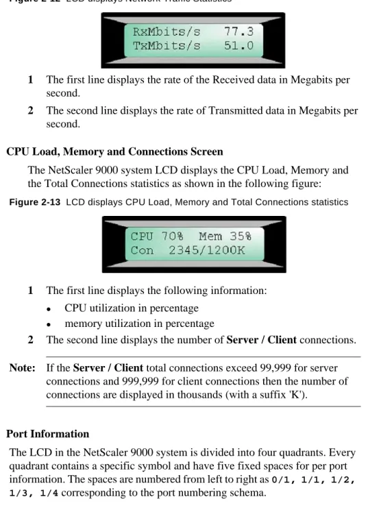
The NetScaler system LCD displays the Network Traffic statistics as shown in the following figure:
Figure 2-12 LCD displays Network Traffic Statistics
1 The first line displays the rate of the Received data in Megabits per second.
2 The second line displays the rate of Transmitted data in Megabits per second.
CPU Load, Memory and Connections Screen
The NetScaler 9000 system LCD displays the CPU Load, Memory and the Total Connections statistics as shown in the following figure:
Figure 2-13 LCD displays CPU Load, Memory and Total Connections statistics
1 The first line displays the following information: z CPU utilization in percentage
z memory utilization in percentage
2 The second line displays the number of Server / Client connections. Note: If the Server / Client total connections exceed 99,999 for server
connections and 999,999 for client connections then the number of connections are displayed in thousands (with a suffix 'K').
Port Information
The LCD in the NetScaler 9000 system is divided into four quadrants. Every quadrant contains a specific symbol and have five fixed spaces for per port information. The spaces are numbered from left to right as 0/1, 1/1, 1/2, 1/3, 1/4 corresponding to the port numbering schema.
Note: The NetScaler 9400 system has only two ports 1/1 and 1/2 and hence uses only second and third space to display the port’s information.
1 First Quadrant (displayed in the Top Left corner as symbol S) This quadrant shows the port speed information. The speed displayed is encoded in special symbols as shown in the following figure:
Figure 2-14 First Quadrant: Port Speed Information
2 Second Quadrant (displayed in the Bottom Left corner as symbol D) This quadrant displays the port duplex information. The duplex status displayed is encoded in special symbols as shown in the following figure:
Figure 2-15 Second Quadrant: Port Duplex Information
3 Third Quadrant (displayed in the Top Right corner as symbol F) Link is down, no speed info is available Speed is 1000 Mbits/s (Gigabit Ethernet) Speed is 10 Mbits/s (plain Ethernet) Speed is 100 Mbits/s (Fast Ethernet) Link is down, no duplex info is available Autosense half duplex mode with Auto duplex requested - possible error conditions Full duplex mode Half duplex
mode with Half duplex requested
This quadrant displays the port flow control information. The flow control status displayed is encoded in special symbols as shown in the following figure:
Figure 2-16 Third Quadrant: Port Flow Control Information
4 Fourth quadrant (displayed in the Bottom Right corner as symbol R) This quadrant displays the PORT Receive (Rx) statistics and PORT Enable state. These statistics are encoded in special symbols as shown in the following figure:
Figure 2-17 Fourth Quadrant: Port Receive Statistics Information
For example
The NetScaler 9400 system LCD screen with two interfaces 1/1 and 1/2 is shown below. Both the interfaces are in 100 Mbit / Half Duplex / No Flow Control / Rx Idle mode.
Link is down, no flow control info is available No flow control Tx only flow control Rxd only flow control Rx/Tx flow control PORT is disabled (see link status in other quadrants) Link is down and PORT is enabled - alert state Rx of 50% of line speed Rx of 100% of line speed Rx less then few percent of line speed
2.2.6 NSLCD program options
The NetScaler 9000 system LCD (NSLCD) program has the following program options available will help you to control the information displayed. Note: The NetScaler 9000 system startup script uses appropriate options
hence customizing the options may be used for very specific requirements.
Table 2-1 List of NSLCD Commands
Option Description NSLCD command
-k Starts the NSLCD in background for NetScaler 9000 system status monitoring
/netscaler/nslcd -k
-h Displays the help screen /netscaler/nslcd -h
-t SEC Sets the refresh rate time
in seconds.
Default refresh rate is 3 seconds.
/netscaler/nslcd -t SEC
-b MIN Sets the back light
time-out in minutes Default value for the back light timeout is 1 minute
/netscaler/nslcd -b MIN
-S Enables serial communications.
/netscaler/nslcd -S
-A Enables alternate device. This option must be used with -Q option. /netscaler/nslcd -A Speed and Flow Control state Duplex and Rx state
-Q Queries LCD type and version.
If the type and version are not correct then the NSLCD will halt with an error message.
/netscaler/nslcd -Q
-K z Runs the NSLCD in loop but not as a daemon.
z Used to tune up the LCD indication.
/netscaler/nslcd -K
-i Skips the introduction screen.
/netscaler/nslcd -i
2.3 Installing the NetScaler 9000 System
This section describes how to install the NetScaler 9000 system on to your network. The steps involved in installing the system are:
z Environment Planning z Pre-Installation Checklist
z Installing the NetScaler 9400 System or Installing NetScaler 9800 System
2.3.1 Environment Planning
This section describes the environments in which the NetScaler 9000 system can be deployed. Before you install the NetScaler 9000 system, use this information to help you determine an appropriate environment for your installation.
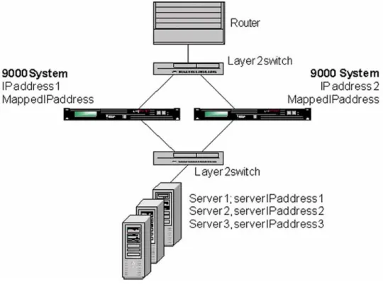
2.3.1.1 Single Subnet
In this type of environment, the NetScaler 9000 system’s IP address, mapped IP address (MIP) and the server’s IP address are on the same subnet. The NetScaler 9000 system can be deployed in one-arm or two-arm mode. Two-Arm Mode (Inline), High Availability
Figure 2-18 on page 15 shows a single subnet environment where the NetScaler 9000 system is in a high availability setup, placed between two layer 2 switches in a two-arm configuration.
The two NetScaler 9000 systems with their IP addresses, mapped IP addresses and the servers with IP addresses are on the same subnet.
Figure 2-18 NetScaler 9000 system in High Availability, Two-Arm Mode (Single Subnet Environment)
One-Arm Mode, High Availability
Figure 2-19 on page 16 shows a single subnet environment where the NetScaler 9000 system is in a high availability setup in a one-arm mode. In this type of deployment, the client must access the servers though a VIP configured on the NetScaler 9000 system.
Figure 2-19 NetScaler 9000 system in High Availability and One-Arm Mode (Single Subnet Environment)
Stand-Alone
To use a NetScaler 9000 system in a single subnet environment and in a stand-alone mode (not in high availability setup), the setup slightly varies from that shown in Figure 2-18 and Figure 2-19. In this case, there is only one NetScaler 9000 system instead of two NetScaler 9000 systems. 2.3.1.2 Multiple Subnets
In this type of environment, the NetScaler 9000 system’s IP address, its mapped IP address (MIP), and the server’s IP address are on different subnets. The NetScaler 9000 system can be used in one-arm or two-arm mode.
Depending on whether the servers are on private (non-routable) subnets, the NetScaler 9000 system can be used either in a public-public or public private type of multiple subnet environments.
Note: If the NetScaler 9000 system is the default router for the servers, then the layer 2 mode can be disabled.
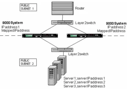
Public-Public
In this environment, the real servers behind the NetScaler 9000 system are on a publicly routable IP subnet. Unlike the public-private
environment (described in the next section), you do not need to configure the NetScaler 9000 system as the default router of the real servers.
Figure 2-20 on page 17 shows a public-public, multiple subnet environment where the NetScaler 9000 system is in a high availability setup, placed between two layer 2 switches in a two-arm configuration. The dashed line shows the separation of two public subnets.
The following applies to this environment:
z Virtual IP addresses (VIPs) configured in the NetScaler 9000 system are on a public subnet.
z The two NetScaler systems, their IP addresses and the mapped IP address are on public subnets.
z The servers and their IP addresses may be either in the same or different public subnets.
This environment can be varied to yield a one-arm mode configuration with or without high availability.
Figure 2-20 NetScaler 9000 system in High Availability and Two-Arm Mode (Multiple Subnet Environment)
Public-Private
When load-balancing a server farm, it may be desirable to hide the IP addresses of the real servers. This can be accomplished by placing the servers on non-routable IP subnets.
Although no router or gateway is usually placed between the NetScaler 9000 system and server farm, the router or gateway can be placed there if required .
In this environment, the servers must be configured with the NetScaler 9000 system as the default router.
Depending on whether the NetScaler 9000 system needs to perform network address translation (NAT) the subnet with the servers should be configured for reverse network address translation (NAT) in the
NetScaler 9000 system. For more information on configuring RNAT in NetScaler 9000 system, see “VLANs Support in Chapter 13”.
This environment is the same as that shown in Figure 2-20 (i.e. the high availability, two-arm mode), except the upper part is a public subnet and the lower part consists of private subnets.
The following applies to this environment:
z Virtual IP addresses (VIPs) configured in the NetScaler 9000 system are on a public subnet.
z The two NetScaler 9000 systems, their IP addresses and the mapped IP address are on public or private subnets.
z The servers and their IP addresses may be either in the same or different private subnets.
This environment can be varied to yield a one-arm mode with or without high availability.
2.3.2 Pre-Installation Checklist
Before installing the NetScaler 9000 system, use the following check list to ensure that you have all of the hardware and software items:
2.3.2.1 Hardware
1. NetScaler 9000 system
2. Brackets to hold NetScaler 9000 system 3. RJ-45-to-RJ-45 Serial Cable
4. One or two AC power cable(s) 5. Two RJ-45-to-DB-9 adapters 6. RJ-45-to-DB-25 adapter 7. Packet of screws
8. Ethernet cables (not supplied) 9. One or two power outlets 10. Rack space
11. Free switch ports to connect to the NetScaler 9000 system
2.3.2.2 Software 1. IP addresses
z One or two NetScaler IP addresses [NSIP] (In HA mode you require two unique NetScaler IP addresses)]
z Appropriate password choices for the root, nsmaint, and nsroot account. As part of the deployment process, these three account passwords must be changed.
Note: In HA mode, when you change the password of the nsroot user account, make sure you change it to the same password on both nodes of the HA pair as password synchronization is required.
z Mapped IP[MIP]
z IP address for the NetScaler 9000 system’s default router z Additional subnet/VLAN IP addresses as needed
2. Additional IP address(s) for any virtual servers (VIPs) that needs to be configured
Note: The NetScaler 9000 system supports any combination of 5000 virtual servers and configured services.
3. For SNMP access to NetScaler 9000 system, you must have
z One Community Name
2.3.3 Installing the NetScaler 9400 System
To install and connect the NetScaler 9400 system into your network: 1. Place the NetScaler 9400 system into the rack.
2. Attach the NetScaler 9400 system to the rack by securing the screws provided, into the holes on each side of the unit’s front.
3. Connect the Ethernet cable(s).
You must provide these cables. These are connected from the Ethernet ports on the front of the NetScaler 9400 system to the Ethernet ports on the devices on your network.
a. Connect one end of a cable to the port labeled 1/1 on the front of the NetScaler 9400 system (see Figure 2-21 on page 21 for the location of this port), then connect the other end to the Ethernet port on the switch.
b. (Optional) Connect one end of another cable to the port labeled 1/2
on the front of the NetScaler 9400 system (see Figure 2-21 on page 21
for the location of this port), then connect the other end to the Ethernet port on the switch.
WARNING! Make sure not to create a network loop — this results if you connect the cable in step 3a and the cable in step 3b to the same switch or VLAN.
Note: If current configuration requires only one Ethernet port to be used then any of ports 1/1 or 1/2 could be used. It is always good idea to DISABLE the unused port(s) (it’s also mandatory in HA
Figure 2-21 Front panel of NetScaler 9400
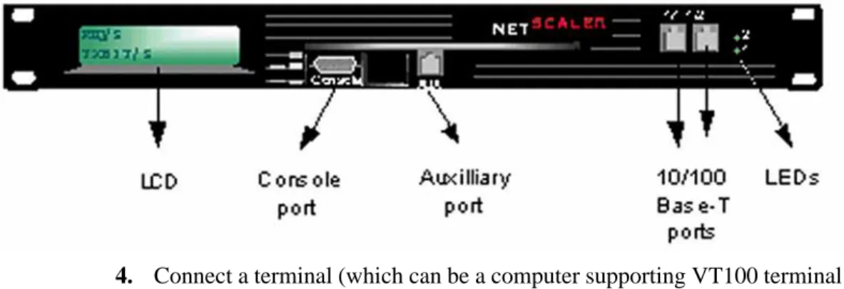
4. Connect a terminal (which can be a computer supporting VT100 terminal emulation) to the console port on the front of the unit.
Note: The terminal that you supply must have a baud rate and character format configured to 9600 baud, 8 data bits, 1 stop bit and no parity. 5. Power-on the NetScaler 9400 system.
Figure 2-22 Back panel of NetScaler 9400
a. Plug-in the power cord that comes with the unit on the back of the NetScaler 9400 system. See the above figure.
b. Depress the On/Off switch present at the back of the unit. The green LED appears lit.
WARNING! After the initial power-on, to power-off the NetScaler 9400 system follow the steps as described in the “Powering-Off the NetScaler 9000 system” on page 44.
z For initial configuration of the NetScaler 9400 system (first time configuration), perform the procedure as described in the Configuring and Starting the NetScaler 9000 system for the First Time section in this chapter.
z If you are reconfiguring the NetScaler 9000 system, perform the
procedure in the Reconfiguring the NetScaler 9000 system section in this chapter.
2.3.4 Installing NetScaler 9800 System
Figure 2-23 on page 23 shows the NetScaler 9000 system NetScaler 9800-SX fiber unit.
Figure 2-24 on page 23 shows the NetScaler 9000 system NetScaler 9800-T copper unit.
To install and connect the NetScaler 9000 system into your network: 1. Place the NetScaler 9000 system into the rack.
2. Attach the NetScaler 9000 system to the rack by securing the screws provided, into the holes on each side of the unit’s front.
3. Connect the Ethernet cables.
You must provide these cables (copper or fiber ones depending on the NetScaler 9000 system used). These are connected from the Ethernet ports on the front of the NetScaler 9000 system to the Ethernet ports on the devices on your network.
a. Connect the end of an Ethernet cable to one of the ports labeled 1/1,
1/2, 1/3 or 1/4 on the front of the NetScaler 9000 system (see Figure 2-23 for port locations), and then connect the other end to the port on the switch. It is not recommended to use the port 0/1 until you have other choices.
b. Connect the end of another cable to any of the available ports labeled
1/1, 1/2, 1/3 or 1/4 on the front of the NetScaler 9000 system (see Figure 2-23 for port locations), and then connect the other end to the port on the switch.
Note: Make sure not to create a network loop — this results if you connect the cable in step 3a and the cable in step 3b to the same switch. In case when current configuration requires less than five ports then any of five available ports could be used (based on Ethernet
technology used). It is good idea to DISABLE all unused ports through software (it is mandatory for HA configuration).
Figure 2-23 Front panel of NetScaler 9800-SX
Figure 2-24 Front of NetScaler 9000 system NetScaler 9800-T
4. Connect a terminal (which can be a computer supporting VT100 terminal emulation) to the console port on the front of the unit.
Note: The terminal that you supply must have a baud rate and character format configured to 9600 baud, 8 data bits, 1 stop bit, and no parity. 5. Power-on the NetScaler 9000 system. Refer to Figure 2-25 on page 24 for
the location of the ON/OFF button.
Figure 2-25 Back panel of NetScaler 9800-T or NetScaler 9800-SX system
a. Plug in the two power cords that come with the unit into the back of the NetScaler 9000 system (see Figure 2-25 for the location of the power).
MAKE SURE that you plug in BOTH power cords.
For 2U NetScaler systems with only one power supply cable plugged in, the system will emit a high pitched alert. This alert can be shut off in one of three ways, depending upon the hardware version.
1. If present, press the small red button at the back of the box near the power plugs. This will have to be done each time the system is powered on.
2. If the red button on the rear of the case is not present, check on the front of the unit around the LCD screen. You will need to remove the faceplate to see the button for silencing the alarm.
3. If neither of these buttons are present on the unit, power cables must be used. The alarm cannot be manually overridden on these units.
b. Turn the switch to the right of the three fans on the back of the unit to the on position.
The green LED above the switch lights and stays lit.
Note: After the initial power-on, turn power off only, as described in the
Powering-Off the NetScaler 9000 system on Page ’44’ in this chapter.
2.3.5 Installation Tips
z If you are setting up the NetScaler 9000 system for the first time, follow the steps given in “Initial Configuration of NetScaler 9000 System” on page 27 of this chapter.
z If you are reconfiguring the NetScaler 9000 system, follow the steps given in the “Reconfiguring the NetScaler 9000 system” on page 43 of this chapter.
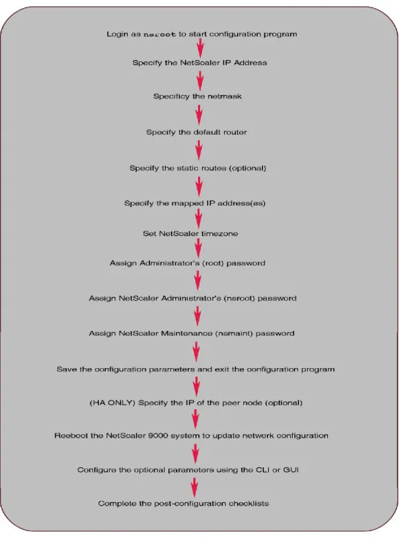
2.4 Configuring the NetScaler 9000 System
Use the console to configure the NetScaler 9000 system using its command line interface (CLI). You can access the CLI using a serial port or Telnet. If you want to use secure communications, you can access the CLI using Secure Shell (SSH).
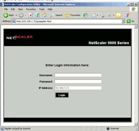
You can also use the NetScaler 9000 system’s GUI to configure the NetScaler 9000 system. The NetScaler 9000 system’s GUI is a Java applet that runs within a web browser. Details about accessing the CLI and GUI are provided later in this chapter.
Figure 2-26 provides an overview of the process you will be following to configure the NetScaler 9000 system.
2.4.1 Initial Configuration of NetScaler 9000 System
This section describes how to configure and start a NetScaler 9000 system when it is powered-on for the first time.
Note: After you configure the parameters in this section, you can continue to configure the optional parameters as described in the section
“Configuring Optional Parameters” on page 36.
1. Configuring the Ethernet Parameters
In the NetScaler 9000 systems, the Ethernet parameters are configured using the set interface CLI command.
For setting the speed/duplex mode, enter the following CLI command: set interface 1/1 -speed 1000 -duplex FULL RXTX
where 1/1 is the interface for which these settings apply. Actually, those parameters cannot be set before the initial configuring is done.
Note:
Compare and confirm the interface settings with the port settings on the switch. Be aware of correct setting of flow control parameters for Gigabit Ethernet and always confirm the resulting settings after the interface came up for the first time.
To compare the interface settings with the actual port settings, use the show interface CLI command on the NetScaler 9x00 system. This command displays the following information:
> show interface
1. Interface 1/2 (NIC 0/dc0) Digital 21143-xD Fast Ethernet flags=0x20c081 <ENABLED, UP, autoneg on, HAMONITOR ON, 802.1q support> mtu=1514, native vlan=1,
eaddr=00:c0:95:c4:c7:50, uptime 52h19m43s
Requested: media AUTO, speed AUTO, duplex AUTO, fctl OF Actual: media UTP, speed 100, duplex FULL, fctl OFF
The interface settings displayed in the Requested row above should match with the port settings on the switch.
2. Starting the Configuration Program
After the NetScaler 9000 system is powered-on, a login prompt is displayed on the terminal attached to the NetScaler 9000 system.
l From the command prompt, login to the nsroot (initial password
for this account is nsroot).
l The NetScaler 9000 system’s configuration program starts.
The following is displayed:
The NetScaler 9000 system has not been configured.
As you enter values for each configuration parameter, the program automatically displays the next screen.
Follow the instructions in each screen.
Note: A value within brackets ([]) indicates the current value that has been set for that parameter. Empty brackets do not have a value set but will show the value after it has been set.
3. Specifying the NetScaler 9000 system’s IP Address
This configuration parameter identifies the NetScaler 9000 system in the network and is used to access the system for management purposes. Enter a unique IP address chosen for this NetScaler 9000 system when the following is displayed:
NetScaler 9000 system’s IP Address
---This specifies the NetScaler 9000 system’s IP address. Enter the NetScaler 9000 system’s IP address []:
4. Specifying the Netmask
This configuration parameter is the netmask for the subnet (network section) into which the NetScaler 9000 system is being installed (for example,
255.255.0.0).
Enter the netmask when the following is displayed: Netmask
---This specifies the netmask for the network in which the NetScaler 9000 system is being installed.
Enter the netmask [0.0.0.0]:
5. Specifying Routes
In the configuration parameter, specify the IP address of the default router to which the NetScaler 9000 system sends packets.
Enter the default router’s IP address when the following message is displayed:
Default Router IP Address
---This specifies the IP address of the default router where packets must be sent by the NetScaler 9000 system if the destination IP address does not belong to the local network.
Enter the IP address of the default router []:
After the default router is set, the following message is displayed:
Do you want to specify additional routes? [NO]:
l If you do not want to make any more changes to the NetScaler 9000
system’s routing table, enter NO and then proceed to the “Specifying the NetScaler 9000 system’s Mapped IP Address” on page 32. —OR—
l Enter YES and proceed to next section: Adding More Routes.
Adding More Routes
Note: The settings in the following routing table are examples that were entered as the default router IP address parameter in the previous configuration steps.
STATIC ROUTES MENU
---This menu allows you to add, modify or remove entries from the NetScaler's static routing table, which is shown below. Note:
- The default router must be specified.
- To apply default router changes, the system must be rebooted.
- Each network can have only one entry in the table. - Routes to multicast addresses are not supported. NetScaler 9000 system ROUTING TABLE
Network Netmask Gateway
---default 0.0.0.0 10.101.0.1
---1. Add static routes.
2. Remove static routes. 3. Remove all static routes. 4. Return to the previous menu. Select a menu item from 1 to 4 [4]: Enter 1 to display the following:
Add or Modify Routing Table Entries ---Enter the routes in the format:
'network:[netmask]:gateway', where 'network' is the IP address of the network where traffic will be routed, 'netmask' will be applied to a destination IP address to determine out the network address belongs to (this is an optional value), and 'gateway' is the IP address of the gateway where traffic will be directed.