The Tangram Framework
Asynchronous Circuits for Low PowerJoep Kessels
Ad Peeters
Philips Research Laboratories
Prof. Holstlaan 4, NL 5656 AA
Eindhoven, The Netherlands
e-mail:
fJoep.Kessels,Ad.Peeters
g@philips.com
Abstract| Asynchronous CMOS circuits have the
potential for very low power consumption, because
they only dissipate when and where active. In
addi-tion they have favorable EMC properties, since they
emit less energy, which in addition is evenly
dis-tributed over the spectrum.
The Tangram framework supports the design of
asynchronous circuits in a high-level programming
language. Using this framework we have designed
sev-eral chips, such as for instance for pagers and smart
cards, which are clearly superior to synchronous
de-signs.
I. Introduction
Compared to clocked circuits, asynchronous circuits oer several attractive properties, such as low power, small current peaks, and low electro-magnetic emission [4]. Asynchronous circuits are, however, dicult to de-sign at the level of gates and registers. Therefore, the high-level design language Tangram was dened and a so-called silicon compiler has been implemented that trans-lates Tangram programs into asynchronous circuits [5].
The paper is organized as follows. Section II presents the Tangram design method, Section III discusses the dif-ferences between synchronous and asynchronous circuits, and Section III presents the most important Tangram de-signs.
II. The Tangram Framework
A. Handshake technology
The design of large scale asynchronous ICs demands a timing discipline to replace the clock regime that is used in conventional VLSI design. We have chosen handshake signaling [25] as the asynchronous timing discipline, since it supports plug-and-play composition of components into systems, and is also easy to implement in VLSI. An alter-native to handshaking would be to compose asynchronous
Active Passive
Active Req - Passive
Ack
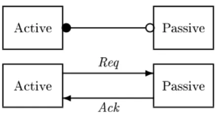
Fig. 1. Handshake channel: abstract gure (top) and implementation (bottom)
nite-state machines that communicate using fundamen-tal mode or burst-mode assumptions. However, attempts to use this path to design industrially sized circuits have suered from severe reliability and interface problems [9]. Fig. 1 shows a handshake channel, which is a point-to-point connection between an active and a passive partner. In the abstract gure, the fat dot indicates the channel's active side and the open circle its passive side. The imple-mentation shows that both partners are connected by two wires: a request (Req) and an acknowledge (Ack) wire. A handshake requires cooperation of both partners. It is initiated by the active party, which starts by sending a signal via Req, and then waits until a signal via Ack ar-rives. The passive side waits until a request arrives, and then sends an acknowledge. Handshake channels can be used not only for synchronization, but also for communi-cation. To that end, data can be encoded in the request, the acknowledge, or in both.
The protocol used in most asynchronous VLSI circuits is a four-phase handshake, in which the channel starts in a state with both Req and Ack low. The active side starts a handshake by making Req high. When this is observed by the passive side, it pulls Ack high. After this a return-to-zero cycle follows, during which rst Req and then Ack go low, thus returning to the initial state.
Handshake components interact with their environment using handshake channels. One can build handshake com-ponents implementing language constructs. Fig. 2 shows
seq a c b par a c b
Fig. 2. Handshake components: sequencer (left) and parallel (right)
Guard do Command
-Fig. 3. Handshake circuit for while loop
two examples: the sequencer and the parallel component. The sequencer, when activated via a, performs rst a
handshake viab and then viac. It is used to control the
sequential execution of commands connected tob and c.
After receiving a request alonga, it sends a request along b, waits for the corresponding acknowledge, then sends
a request along c, waits for the acknowledge on c, and
nally signals completion of its operation by sending an acknowledge along channela.
The parallel component, when activated by a request along a, sends requests along channels b and c
concur-rently, waits until both acknowledges have arrived, and then sends an acknowledge along channela.
Components for storage of data (variables) and oper-ation on data (like addition and bit-manipuloper-ation) can also be constructed. Tangram programs are compiled into handshake circuits (composition of handshake ponents) in a syntax-directed way. For instance, the com-pilation of a while loop
whileGuarddoCommand
results in the handshake circuit shown in Fig. 3. The do-component, when activated, collects the value of the guard. When the guard is false, it completes the hand-shake on its passive port, otherwise it activates the com-mand, and after its completion re-evaluates the guard to start a new cycle.
Details about handshake circuits, the compilation from Tangram into this intermediate architecture, and of the gate-level implementation of handshake components can be found in [5, 2, 22].
B. The Tangram Toolset
Fig. 4 shows the Tangram toolset. The designer de-scribes his design in Tangram, which is a conventional programming language, like C or Pascal, extended to in-clude constructs for expressing concurrency and
commu-Tangram Program Tangram Compiler Handshake Circuit Component Expander Abstract Netlist Technology Mapper Mapped Netlist ? ? ? ? ? ? Function, Area Timing, Power, Test
Performance Analyzer Timed Traces Fault Coverage Handshake Circuit Simulator 6 6 6 -Component Library Asynchronous Library Standard-cell Library
Fig. 4. The Tangram toolset: boxes denote tools, ovals denote (design) representations.
nication in a way similar to those in the language CSP [12]. In addition to this, there are language constructs for expressing hardware-specic issues, like sharing of blocks and waiting for clock-edges.
A compiler translates Tangram programs into so-called handshake circuits, which are netlists composed from a library of some 40 handshake components. Each hand-shake component implements a language construct, like sequencing, repetition, communication, and sharing.
The handshake circuit simulator and corresponding performance analyzer give feedback to the designer about aspects such as function, area, timing, power, and testa-bility.
The actual mapping onto a conventional (synchronous) standard-cell library is done in two steps. In the rst step the component expander uses the component library to generate an abstract netlist consisting of combinational logic, registers, and asynchronous cells, such as Muller C-elements. In the second step commercial synthesis tools and technology mappers are used to generate the standard-cell netlist. No dedicated (asynchronous) cells are required in this mapping, because all asynchronous cells are decomposed in cells from the standard-cell
li-brary at hand using a separate asynchronous lili-brary. Similar language-based approaches using handshake circuits as intermediate format are described in [7, 1]. Design approaches in which asynchronous details are not hidden for the designer have also proven successful [19, 8, 10, 15]. A general overview of design methods for asynchronous circuits is given in [16].
III. Differences between synchronous and asynchronous circuits
When the asynchronous circuits generated by the Tan-gram compiler are compared to synchronous ones, three dierences stand out, leading to four attractive properties of these asynchronous circuits.
1. The subcircuits in a synchronous circuit are clock-driven, whereas they are demand-driven in an asyn-chronous one. This means that the subcircuits in an asynchronous circuit are only active when and where needed. Asynchronous circuits will therefore gener-ally dissipate less power than synchronous ones. 2. The operations in a synchronous circuit are
nized by a central clock, whereas they are synchro-nized by distributed handshakes in an asynchronous circuit. Therefore
a) a synchronous circuit shows large current peaks at the clock edges, whereas the power consump-tion of an asynchronous circuit is more uni-formly distributed over time;
b) the strict periodicity of the current peaks in a synchronous circuit leads to higher clock har-monics in the emission spectrum, which are ab-sent in the spectrum of an asynchronous design. 3. Synchronous circuits use an external time reference, whereas asynchronous circuits are self-timed. This means that asynchronous circuits operate over a wide range of the supply voltage (for instance, from 1 up to 3.3 V) while automatically adapting their speed. This property, called automatic performance adapta-tion, implies that asynchronous circuits are resilient to supply-voltage variations. It can also be used to reduce the power consumption by adaptive voltage scaling, which means adapting the supply voltage to the performance required [21]. Adaptive voltage scal-ing techniques are also applied in synchronous cir-cuits, but then special measures must be taken to adapt the clock frequency.
Asynchronous circuits have also drawbacks. The most important one is their unconventionality, which means that designers and mainstream tools and libraries are all oriented towards synchronous design methods. Addi-tional drawbacks of asynchronous circuits come from the fact that they use gates to control registers (latches and
ip-ops), instead of the relatively straightforward clock-distribution network in synchronous circuits. Although this enables the low power consumption it also leads to circuits that are typically larger, slower, and harder to test. Testability issues of asynchronous circuits are dis-cussed in [14, 24].
IV. Exploitation
To demonstrate the potential of asynchronous circuits as well as the viability of the Tangram framework, we have designed several chips in Tangram. The most important ones are presented below.
A. The DCC error corrector
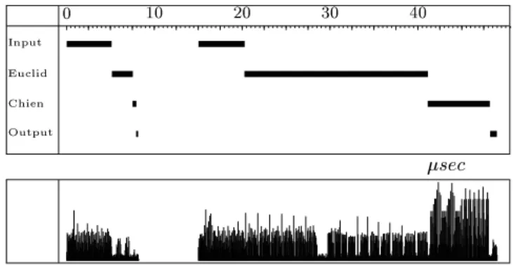
The rst major demonstrator was an error corrector for the Digital Compact Cassette (DCC) player, consisting of two asynchronous chips [3]. These chips have been fab-ricated and incorporated successfully in an experimental DCC system. sec 0 10 20 30 40 Input Euclid Chien Output
Fig. 5. Simulation of rst a correct and then an incorrect code word
As might be expected, error correction is much simpler for a correct word than for an incorrect one. Fig. 5 shows both the time and the power required to decode rst a correct and then an incorrect code word. The processing of the decoder for correct words takes only 30% of the time needed for incorrect ones and during that time only 25% of the ipops are active. Power measurements of the decoder chip show that a correct word requires only one seventh of the energy needed for an incorrect one. Compared to existing clocked implementations, the asyn-chronous decoder is 20% larger in area and is ve times more power ecient.
The performance adaptivity of asynchronous circuits has been exploited to reduce the power dissipation further by switching between supply voltages, a technique called voltage scheduling [6]. The chip has two power pins: one for a low and one for a high voltage. In the normal case of correct words, which only take a short time to handle, the chip operates on a low voltage and only that part of
the computation that is conditional on the word being incorrect is performed on a high voltage. This additional measure leads to a further power reduction by a factor 20 [17].
B. The 80C51 micro-controller
The 80C51 micro-controller has been designed in Tan-gram [11]. In the next three paragraphs we compare the asynchronous version with a synchronous version giving the same performance at the same supply voltage.
The average power consumption of the asynchronous 80C51 is about three times lower than the power con-sumption of its synchronous counterpart. This dierence in average power consumption is visualized in g. 6, which shows the light emission of both the synchronous and the asynchronous 80C51, where a light spot indicates switch-ing activity. Both versions are performswitch-ing the same task. Fig. 7 shows the current peaks of both the synchronous and the asynchronous 80C51 at 3.3 V, where the asyn-chronous version is running at a speed that is 2.5 times higher than the synchronous one (the synchronous one runs at 10 MHz and the asynchronous one at a speed cor-responding to 25 MHz). Despite the fact that the gure does not give a fair impression of the average power be-ing consumed, it clearly shows that the current peaks of the asynchronous 80C51 are about ve times smaller than those of the synchronous one.
Fig. 8 shows the emission spectra of both the chronous and the asynchronous 80C51. For the syn-chronous version higher clock harmonics are still visi-ble around 250 MHz, whereas the spectrum of the asyn-chronous one is like white noise for frequencies higher than 50 MHz.
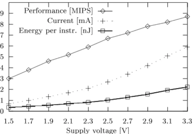
The performance adaptation property of asynchronous circuits is illustrated in g. 9, which shows the free-running performance of the micro-controller, when exe-cuting code from ROM, as a function of the supply volt-age. As could be expected, the performance depends lin-early on the supply voltage. When the supply voltage goes up from 1.5 to 3.3 V, the performance increases from 3 to 8.7 MIPS (about a factor 3). Since the ROM containing the program does not function properly when the supply voltage is below 1.5 V, we could not measure the per-formance for lower values. We observed, however, that asynchronous circuits that do not need a memory, still function correctly at a supply voltage level as low as 0.5 V. The gure also shows the supply current as a function of the supply voltage. Note that the current increases in this range from 0.7 to 6 mA (about a factor 9). Since in CMOS circuits, the current is the product of the tran-sition rate (performance) and the charge being switched per transition (both of which depend linearly on the sup-ply voltage), the current increases with the square of the voltage. From this it follows that the power, being the product of the current and the voltage, goes up with the cube of the voltage. From this data one can compute
Fig. 6. Light emission of synchronous (left) and asynchronous (right) 80C51
100
0 1 2 0 1 2
Time[µsec] I[mA]
Fig. 7. Current peaks of synchronous (left) and asynchronous (right) 80C51
dBµV
0 250 500 0 250 500
Freq[ΜΗz] 80
Fig. 8. Emission spectrum of synchronous (left) and asynchronous (right) 80C51
the third curve showing the average energy needed to ex-ecute an instruction, which increases with the square of the supply voltage from 0.35 to 2.25 nJ.
C. Pager chips
The rst commercial product designed with the Tan-gram framework is the PC500x family of pager chips [13]. This family has been designed at Philips Semiconductors Zurich and is based on the asynchronous 80C51 micro-controller. The main reason for an asynchronous design was reducing the electro-magnetic emission.
In most of the current pager products, the microcon-troller has to be deactivated during reception of a mes-sage to avoid interference with the highly sensitive radio receiver. Therefore decoding is performed by a dedicated
0 1 2 3 4 5 6 7 8 9 1.5 1.7 1.9 2.1 2.3 2.5 2.7 2.9 3.1 3.3 Supply voltage [V] Performance [MIPS] 3 3 3 3 3 3 3 3 3 3 3 Current [mA] + + + + + + + + + + + Energy per instr. [nJ] 2
2 2 2 2 2 2 2 2 2 2
Fig. 9. Performance adaptation of asynchronous 80C51
decoder IC that can handle only one paging protocol (cur-rently there are several protocols in use, the most common are POCSAG, FLEX and ERMES.)
In the PC500x pager chips, the absence of clock har-monics in the emission spectrum of the asynchronous 80C51 microcontroller, reduced the electro-magnetic in-terference to a degree allowing the microcontroller to be active also during reception. Therefore, the majority of the decoder functionality could be implemented in soft-ware resulting in a low-cost paging chip, which can handle any protocol using dedicated software.
D. Smart-card chips
A contactless smart-card chip has been designed in Tan-gram [18]. Such a chip must be extremely power ecient, since it is powered by electromagnetic radiation only. Al-though low power is also important in battery-powered devices, there are two crucial dierences between both kind of devices.
1. The supply voltage is nearly constant in battery pow-ered devices, whereas in contactless ones it may vary during a transaction due to uctuations in both the incoming and the consumed power.
2. To maximize the battery life-time in battery-powered devices, one should minimize the average power consumption. In contactless devices, however, one should in addition minimize the peak power, since the peaks must be kept below a certain level, depending on the incoming power as well as the buer capacitor. These two dierences indicate that asynchronous circuits may be very suited for contactless devices. Firstly, when designed properly, asynchronous circuits can deal with a uctuating supply voltage due to their performance adap-tivity. Secondly, asynchronous circuits have, compared to synchronous ones, a low average power, which is good, but they show even a lower peak power, which is exactly what is needed in contactless devices.
We have built the digital circuit shown in Fig. 10 that consists of:
- an 80C51 micro-controller;
- 2 kbyte of RAM, 32 kbyte of EEPROM, and 38 kbyte of ROM, each equipped with a handshake interface; - two encryption co-processors: an RSA converter [23] for public key conversions and a triple-DES converter [20] for private key conversions;
- a UART for the external communication.
Apart from the RSA converter, all modules have been designed using the Tangram framework.
DES RSA UART 80c51 Micro-controller RAM ROM EEPROM
Fig. 10. Global design of the smart-card circuit
Measurements and simulations demonstrated at least two advantages of this design when compared to a con-ventional synchronous one.
First of all, the asynchronous circuit gives the maxi-mum performance for the power received, which is about four times more than the performance of the equivalent synchronous circuit. This comes from two facts, which both double the performance. In the rst place, the asyn-chronous design needs less of what is the main limiting factor for the performance, namely power. Compared to a synchronous design, the asynchronous circuit needs about 60% less power for less than 2% additional area (in the comparison we included the memories). In the second place, the automatic speed adaptation property of asyn-chronous circuits saves the designer from trading o be-tween performance and robustness. Due to this property the asynchronous circuit will give free-running instead of guaranteed performance.
Secondly, the asynchronous design is more robust; a property that is hard to quantify. In the rst place, the current peaks of an asynchronous circuit are less pro-nounced leading to smaller voltage drops. Secondly, the speed adaptation property makes the circuit more resilient to voltage drops, since it still operates correctly for volt-ages down to 1.5 V. For an asynchronous smart-card this could imply that fewer transactions are canceled, leading to greater customer satisfaction, and possibly to faster ow-trough of people when applied in public transport.
V. Conclusion
Using the Tangram framework, asynchronous circuits have been designed that convincingly demonstrate several attractive properties, such as low power, small current peaks, low EMI, and automatic performance adaptation to voltage scaling. Currently, however, the mainstream design paradigm is synchronous, which means that most designers, tools and libraries are oriented towards syn-chronous designs. Therefore, asynsyn-chronous circuits will only be applied if the advantages are substantial.
We have identied several areas, such as embedded micro-controllers, pagers and smart card chips, in which asynchronous circuits oer such substantial advantages.
Acknowledgements
We gratefully acknowledge all the other members of the Tangram team (current and old): Kees van Berkel, Ronan Burgess, Hans van Gageldonk, Marly Roncken, Ronald Saeijs, Frits Schalij, Marc Verra, Rik van der Wiel, and Erwin Woutersen; and the people in the product divisions with whom we designed the application chips: Daniel Baumann, Daniel Gloor, Torsten Kramer, Gerhard Stegmann, Volker Timm, and Klaus Ully.
Part of the work described here has been funded by the European Commission under Esprit project 25519 (Descale), EP21949 (ACiD-wg), and EP6143 (EXACT).
References
[1] A. Bardsley and D. Edwards. Compiling the language Balsa to delay-insensitive hardware. In C. D. Kloos and
E. Cerny, editors,Hardware Description Languages and
their Applications (CHDL), pages 89{91, Apr. 1997.
[2] K. v. Berkel. Handshake Circuits: an Asynchronous
Ar-chitecture for VLSI Programming, volume 5 of Interna-tional Series on Parallel Computation. Cambridge Uni-versity Press, 1993.
[3] K. v. Berkel, R. Burgess, J. Kessels, A. Peeters, M. Ron-cken, and F. Schalij. Asynchronous circuits for low power:
A DCC error corrector.IEEE Design & Test of
Comput-ers, 11(2):22{32, Summer 1994.
[4] K. v. Berkel, M. B. Josephs, and S. M. Nowick. Scanning the technology: Applications of asynchronous circuits.
Proceedings of the IEEE, 87(2):223{233, Feb. 1999. [5] K. v. Berkel, J. Kessels, M. Roncken, R. Saeijs, and
F. Schalij. The VLSI-programming language Tangram
and its translation into handshake circuits. InProc.
Eu-ropean Conference on Design Automation (EDAC), pages 384{389, 1991.
[6] K. v. Berkel, H. van Gageldonk, J. Kessels, C. Niessen, A. Peeters, M. Roncken, and R. van de Wiel.
Asyn-chronous does notimplylow power, but .... In A.
Chan-drakasan and R. Brodersen, editors, Low Power CMOS
Design, pages 227{232. IEEE Press, 1998.
[7] E. Brunvand and R. F. Sproull. Translating concurrent
programs into delay-insensitive circuits. InProc.
Inter-national Conf. Computer-Aided Design (ICCAD), pages 262{265. IEEE Computer Society Press, Nov. 1989.
[8] S. M. Burns and A. J. Martin. Syntax-directed transla-tion of concurrent programs into self-timed circuits. In
J. Allen and F. Leighton, editors, Advanced Research in
VLSI, pages 35{50. MIT Press, 1988.
[9] B. Coates, A. Davis, and K. Stevens. The Post Oce
experience: Designing a large asynchronous chip.
Inte-gration, the VLSI journal, 15(3):341{366, Oct. 1993. [10] J. Cortadella, M. Kishinevsky, A. Kondratyev,
L. Lavagno, and A. Yakovlev. Petrify: a tool for manipulating concurrent specications and synthesis
of asynchronous controllers. IEICE Transactions on
Information and Systems, E80-D(3):315{325, Mar. 1997. [11] H. v. Gageldonk, D. Baumann, K. van Berkel, D. Gloor, A. Peeters, and G. Stegmann. An asynchronous
low-power 80c51 microcontroller. InProc. International
Sym-posium on Advanced Research in Asynchronous Circuits and Systems, pages 96{107, 1998.
[12] C. A. R. Hoare. Communicating Sequential Processes.
Prentice-Hall, 1985.
[13] http://www.semiconductors.philips.com/pip/PCA5007H. PCA5007: Pager baseband controller. Philips Semicon-ductors.
[14] H. Hulgaard, S. M. Burns, and G. Borriello. Testing
asynchronous circuits: A survey. Integration, the VLSI
journal, 19(3):111{131, Nov. 1995.
[15] H. Jacobson, E. Brunvand, G. Gopalakrishnan, and P. Kudva. High-level asynchronous system design using
the ACK framework. InProc. International Symposium
on Advanced Research in Asynchronous Circuits and
Sys-tems, pages 93{103. IEEE Computer Society Press, Apr.
2000.
[16] M. B. Josephs, S. M. Nowick, and C. H. K. van Berkel.
Modeling and design of asynchronous circuits.
Proceed-ings of the IEEE, 87(2):234{242, Feb. 1999.
[17] J. Kessels. VLSI programming of a low-power asyn-chronous Reed-Solomon decoder for the DCC player. In
Asynchronous Design Methodologies, pages 44{52. IEEE Computer Society Press, May 1995.
[18] J. Kessels, T. Kramer, G. den Besten, A. Peeters, and V. Timm. Applying asynchronous circuits in contactless
smart cards. InProc. International Symposium on
Ad-vanced Research in Asynchronous Circuits and Systems, pages 36{44. IEEE Computer Society Press, Apr. 2000. [19] A. J. Martin. Compiling communicating processes into
delay-insensitive VLSI circuits. Distributed Computing,
1(4):226{234, 1986.
[20] National Bureau of Standards. Data encryption stan-dard, Jan. 1977. Federal Information Processing Stan-dards Publication 46.
[21] L. S. Nielsen, C. Niessen, J. Spars, and C. H. van Berkel. Low-power operation using self-timed and adaptive
scal-ing of the supply voltage. IEEE Transactions on VLSI
Systems, 2(4):391{397, Dec. 1994.
[22] A. M. G. Peeters. Single-Rail Handshake Circuits. PhD
thesis, Eindhoven University of Technology, June 1996. [23] R. Rivest, A. Shamir, and L. Adleman. A method for
ob-taining digital signatures and public-key cryptosystems.
Comm. of the ACM, 21:120{126, June 1978.
[24] M. Roncken. Defect-oriented testability for asynchronous
IC's. Proceedings of the IEEE, 87(2):363{375, Feb. 1999.
[25] C. L. Seitz. System timing. In C. A. Mead and L. A.
Con-way, editors, Introduction to VLSI Systems, chapter 7.