Verification Examples
Linear static
... 3
Supported bar with concentrated loads. ... 4
Thermally loaded bar structure. ... 5
Continously supported beam with point loads. ... 6
External prestressed beam. ... 9
Periodically supported infinite membrane wall with constant distributed load. ... 11
Clamped beam examination with plane stress elements. ... 13
Clamped thin square plate. ... 16
Simply supported XLAM plate. ... 18
Plate with fixed support and constant distributed load. ... 21
Annular plate. ... 22
All edges simply supported plate with partial distributed load. ... 24
Clamped plate with linear distributed load. ... 26
Hemisphere displacement. ... 28
Nonlinear static
... 30
3D beam structure. ... 31
Plate with fixed end and bending moment. ... 33
Dynamic
... 36
Deep simply supported beam. ... 37
Clamped thin rhombic plate. ... 40
Cantilevered thin square plate. ... 42
Cantilevered tapered membrane. ... 45
Flat grillages. ... 48
Stability
... 52
Simply supported beam. ... 53
Simply supported beam. ... 55
Design
... 56
N-M interaction curve of cross-section (EN 1992-1-1:2004). ... 57
RC beam deflection according to EC2, EN 1992-1-1:2010. ... 58
Nonlinear analysis of RC columns according to EC2, EN 1992-1-1:2010. ... 60
Required steel reinforcement of RC plate according to EC2, EN 1992-1-1:2004. ... 62
Interaction check of simply supported beam under biaxial bending (EN 1993-1-1). ... 64
Interaction check of simply supported beam under normal force, bending and shear force. ... 66
Buckling resistance of simply supported beam (EN 1993-1-1). ... 68
Buckling resistance of simply supported beam (EN 1993-1-1). ... 70
Buckling of a hollow cross-section beam (EN 1993-1-1). ... 72
Lateral torsional buckling of a beam (EN 1993-1-1). ... 76
Interaction check of beam in section class 4 (EN 1993-1-1, EN 1993-1-5) ... 82
Earth-quake design using response-spectrum method. ... 85
Plastic material ... 92
Clamped beam with plastic material under cyclic loading ... 93
File name: beam1.axs
Thema Supported bar with concentrated loads.
Analysis
Type Linear analysis.
Geometry
Side view Section Area = 100,0 cm2 (10×10)
Loads Axial direction forces P1 = -200 kN, P2 = 100 kN, P3 = -40 kN
Boundary
Conditions Fix ends, at R
1 and R5. Material Properties E = 20000 kN / cm 2 = 0,3 Element types Beam element Mesh Target R1 , R5 support forces
Results
Theory AxisVM %
R1 [kN] -22,00 -22,00 0,00
Software Release Number: R3 Date: 17. 08. 2015.
Tested by: InterCAD Page number:
File name: beam2.axs
Thema Thermally loaded bar structure.
Analysis
Type Linear analysis.
Geometry
Side view Sections:
Steel: AS =
x 10-4 m2 (D=2cm)Copper: AC =
x 10-4 m2 (D=2cm)Loads P = -12 kN (Point load)
Temperature rise of 10 C in the structure after assembly. Boundary
Conditions The upper end of bars are fixed. Nodal DOF: Frame X-Z plane Material
Properties Steel: ES = 20700 kN / cm2 , = 0,3 ,
S = 1,2 x 10⁻⁵C-1 Copper: EC = 11040 kN / cm2 , = 0,3 ,
C = 1,7 x 10⁻⁵C-1Element
types Beam element
Target Smax in the three bars.
Results
Theory AxisVM %
Steel Smax [MPa] 23,824 23,848 0,10
Cooper Smax [MPa] 7,185 7,199 0,19
z
File name: beam3.axs
Thema Continously supported beam with point loads.
Analysis
Type Linear analysis.
Geometry
Side view
(Section width = 1,00 m, height1 = 0,30 m, height2 = 0,60 m)
Loads P1= -300 kN, P2= -1250 kN, P3= -800 kN, P4= -450 kN Boundary Conditions Elastic supported. From A to D is Kz = 25000 kN/m/m. From D to F is Kz = 15000 kN/m/m.
Nodal DOF: Frame X-Z plane Material
Properties
E = 3000 kN/cm2 = 0,3
Element
types Rib element: Three node beam element. Shear deformation is taken into account.
Target ez, My, Vz, Rz
Results
Diagram ez
Results Diagram Vz Diagram Rz Reference AxisVM e [%] eA [m] 0,006 0,006 0,00 eB [m] 0,009 0,009 0,00 eC [m] 0,014 0,014 0,00 eD [m] 0,015 0,015 0,00 eE [m] 0,015 0,015 0,00 eF [m] 0,013 0,013 0,00 Reference AxisVM e [%] MA [KNm] 0,0 0,2 0,00 MB [KNm] 88,5 87,1 -1,58 MC [KNm] 636,2 630,8 -0,85 MD [KNm] 332,8 330,1 -0,81 ME [KNm] 164,2 163,0 -0,73 MF [KNm] 0,0 0,4 0,00
VA [KN] 0,0 0,1 0,00 VB [KN] 112,1 113,1 0,89 VC [KN] 646,8 647,2 0,06 VD [KN] 335,0 334,9 -0,03 VE [KN] 267,8 267,5 -0,11 VF [KN] 0,0 -0,1 0,00 Reference AxisVM e [%] RA [KN/m2] 145,7 154,0 5,70 RB [KN/m2] 219,5 219,4 -0,05 RC [KN/m2] 343,8 346,0 0,64 RD [KN/m2] 386,9 386,4 -0,13 RE [KN/m2] 224,5 224,7 0,09 RF [KN/m2] 201,2 200,8 -0,20
Software Release Number: R3 Date: 17. 08. 2015.
Tested by: InterCAD Page number:
File name: beam4.axs
Thema External prestressed beam.
Analysis
Type Linear analysis.
Geometry
Side view
Loads p = -50 kN /m distributed load
Length change = -6,52E-3 at beam 5-6 Boundary Conditions eY = eZ = = 0 at node 1 eX = eY = eZ = 0 at node 4 Material Properties E = 2,1E11 N / m 2
Beam 1-5, 5-6, 6-4 A = 4,5E-3 m2 Iz= 0,2E-5 m4
Truss 2-5, 3-6 A = 3,48E-3 m2 Iz= 0,2E-5 m4
Beam 1-4 A = 1,516E-2 m2 Iz= 2,174E-4 m4
Mesh Beam 1-4: division into N segment: N = 12
Element
types Rib element: Three node beam element, 1-5, 5-6, 6-4, 1-4 (shear deformation is taken into account) Truss element 2-5, 3-6
Target NX at beam 1-4
My,max at beam 2-3
Diagram ez
ROBOT V6® AxisVM %
Nx [kN] 584,56 584,81 0,04
My [kNm] 49,26 49,60 0,68
Software Release Number: R3 Date: 17. 08. 2015.
Tested by: InterCAD Page number:
File name: plane1.axs
Thema Periodically supported infinite membrane wall with constant distributed load.
Analysis
Type Linear analysis.
Geometry Side view (thickness = 20,0 cm) Loads p = 200 kN / m Boundary Conditions
vertical support at every 4,0 m support length is 0,4 m (Rz = 1E+3) Symmetry edges – Nodal DOF: (C C f C C C)
Material
Properties E = 880 kN / cm
2 = 0,16
Element
types Parabolic quadrilateral membrane (plane stress)
Mesh
Node
Analytical [kN/cm
2]
AxisVM [kN/cm
2]
%
1
0,1313
0,1310
-0,23
2
0,0399
0,0395
-1,00
3
-0,0093
-0,0095
2,15
4
-0,0412
-0,0413
0,24
5
-0,1073
-0,1070
-0,28
6
-0,9317
-0,9166
-1,62
7
0,0401
0,0426
6,23
8
0,0465
0,0469
0,86
9
0,0538
0,0537
-0,19
10
0,1249
0,1245
-0,32
Reference:Dr. Bölcskey Elemér – Dr. Orosz Árpád:
Software Release Number: R3 Date: 17. 08. 2015.
Tested by: InterCAD Page number:
File name: plane2.axs
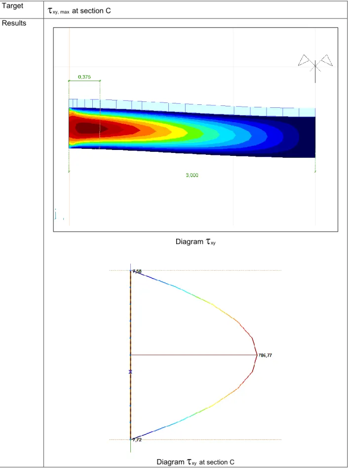
Thema Clamped beam examination with plane stress elements.
Analysis
Type Linear analysis.
Geometry
Side view
Loads p = -25 kN/m
Boundary
Conditions Both ends built-in. Line support component stiffness: 1E+10. Symmetry edge – Nodal DOF: (C C f C C C) Material Properties E = 880 kN / cm 2 = 0 Element types
Parabolic quadrilateral membrane (plane stress) Mesh
Diagram xy
2 ' 4 3 ' / 5 , 787 00260416 , 0 25 , 0 0078125 , 0 625 , 65 00260416 , 0 25 , 0 0078125 , 0 ) ( 625 , 65 m kN I b S V m I m b m S theory beam from kN V y y xy y y
AxisVM result
xy= 786,8 kN / m2 Difference = -0,09 % AxisVM result V
nxy 65,33 kN Difference = -0,45 %File name: plate1.axs
Thema Clamped thin square plate.
Analysis
Type Linear analysis.
Geometry
Top view (thickness = 5,0 cm)
Loads P = -10 kN (at the middle of the plate)
Boundary Conditions
eX = eY = eZ = fiX = fiY = fiZ = 0 along all edges Nodal DOF: Plate in X-Y plane
Material Properties E = 20000 kN / cm 2 = 0,3 Element types
Plate element (Parabolic quadrilateral, heterosis) Mesh
Results
Displacements
Mode Mesh Book1 Timoshenko2 AxisVM Diff1 [%] Diff2 [%]
1
2x2
0,402
0,420
4,48
10,53
24x4
0,416
0,369
-11,30
-2,89
38x8
0,394
0,381
-3,30
0,26
412x12
0,387
0,383
-1,03
0,79
516x16
0,385
0,383
-0,52
0,79
0,38
References:1.) The Finite Element Method (Fourth Edition) Volume 2.
/O.C. Zienkiewicz and R.L. Taylor/ McGraw-Hill Book Company 1991 London 2.) Result of analytical solution of Timoshenko
Convergency -15,00 -10,00 -5,00 0,00 5,00 10,00 15,00 1 2 3 4 5 Mesh density D is pla c e me nt s Diff1 [%] Diff2 [%]
File name: XLAM_Example_1.axs
Thema Simply supported XLAM plate.
Analysis
Type Linear analysis.
Geometry
Top view (x-y plane)
Loads P = -100 kN concentrated force acting at point (x = 9.0 m, y = 2.5 m)
PZ = -5.00 kN/m2 uniform load
Boundary
Conditions eX = eY = eZ = fiY = fiZ = 0, fiX = free along top and bottom edges eX = eY = eZ = fiX = fiZ = 0, fiY = free along left and right edges Nodal DOF at the remaining nodes: Plate in X-Y plane
Material
Properties Material quality equals to C24 timber. Section
Properties MM 7s/240 XLAM section with “x” oriented top layer grain direction and Service Class 2, producing an overall thickness of 240 mm. Element
types Plate element (Parabolic quadrilateral, heterosis)
Mesh
Average element length is 0.2 m.
Target Displacement and stresses at node 397 (x = 8.022 m, y = 3.750 m), material stiffness
matrix, shear correction factors.
Displacements and stresses with Axis VM, ANSYS and from Navier solution1
x y Description AxisVM ANSYS Diff [%] solutionNavier Diff [%] 8.022 m
3.750 m
e
z[mm]
-18.024 -18.023
0.01
-18.024
0.00
σx maximum [N/mm2] 8.022 m3.750 m
2.812
2.805
0.28
2.812
-0.0256
-0.23
8.022 m3.750 m
σy maximum [N/mm2]4.995
4.951
0.89
4.982
0.02
8.022 m3.750 m
τxz maximum [N/mm2]-0.0257 -0.0258
0.02
0.26
0.27
0.11
8.022 m3.750 m
τyz maximum [N/mm2]0.0898
0.0898
0.0897
Material stiffness matrix and shear correction factors from ANSYS2
Material stiffness matrix and shear correction factos from Axis VM3
Shear terms4
Shear correction factors
1 : with 50 harmonic terms included 2 : units in [N] and [mm]
3 : units in [kN] and [m] 4 : corrected shear stiffnesses
Software Release Number: R3 Date: 17. 08. 2015.
Tested by: InterCAD Page number:
File name: plate2_1.axs
Thema Plate with fixed support and constant distributed load.
Analysis
Type Linear analysis.
Geometry
Top view (thickness = 15,0 cm)
Loads P = -5 kN / m2
Boundary
Conditions eX = eY = eZ = fiX = fiY = fiZ = 0 along all edges Nodal DOF: Plate in X-Y plane Material Properties E = 990 kN/cm 2 = 0,16 Element types
Parabolic triangle plate element Mesh
Target Maximal eZ (found at Node1) and maximal mx (found at Node2)
Results
Component
Nastran®
AxisVM
%
eZ,max [mm]
-1,613
-1,593
-1,24
File name: plate3.axs
Thema Annular plate.
Analysis
Type Linear analysis.
Geometry
Top view (thickness = 22,0 cm)
Loads Edge load: Q = 100 kN / m
Distributed load: q = 100 kN / m2
Boundary
Conditions Nodal DOF: Plate in X-Y plane
Material
Properties E = 880 kN / cm
2 = 0,3
Element
Mesh
Target Smax, emax
Results
Theory
AxisVM
Model
S
maxS
max%
[kN/cm2]
[kN/cm2]
a.) 2,82 2,78 -1,42 b.) 6,88 6,76 -1,74 c.) 14,22 14,10 -0,84 d.) 1,33 1,33 0,00 e.) 2,35 2,25 -4,26 f.) 9,88 9,88 0,00 g.) 4,79 4,76 -0,63 h.) 7,86 7,86 0,00Theory
AxisVM
Model
e
maxe
max%
[mm]
[mm]
a.) 77,68 76,10 -2,03 b.) 226,76 220,84 -2,61 c.) 355,17 352,89 -0,64 d.) 23,28 23,42 0,60 e.) 44,26 44,50 0,54 f.) 123,19 123,17 -0,02 g.) 112,14 111,94 -0,18 h.) 126,83 126,81 -0,02 Reference:File name: plate4.axs
Thema All edges simply supported plate with partial distributed load.
Analysis
Type Linear analysis.
Geometry
Top view (thickness = 22,0 cm)
Loads Distributed load: q = -10 kN / m2 (middle of the plate at 2,0 x 2,0 m area)
Boundary Conditions
a.) eX = eY = eZ = 0 along all edges (soft support)
b.) eX = eY = eZ = 0 along all edges = 0 perpendicular the edges (hard support) Nodal DOF: Plate in X-Y plane
Material Properties E = 880 kN / cm 2 = 0,3 Element types
Plate element (Heterosis) Mesh
Target mx, max, my, max
Results a.)
Moment
Theory
AxisVM
%
m
x, max[kNm/m]
7,24
7,34
1,38
m
y, max[kNm/m]
5,32
5,39
1,32
b.)
Moment
Theory
AxisVM
%
m
x, max[kNm/m]
7,24
7,28
0,55
m
y, max[kNm/m]
5,32
5,35
0,56
Reference:
File name: plate5.axs
Thema Clamped plate with linear distributed load.
Analysis
Type Linear analysis.
Geometry
Top view (thickness = 22,0 cm)
Loads Distributed load: q = -10 kN / m2
Boundary
Conditions eX = eY = eZ = fiX = fiY= fiZ = 0 along all edges Nodal DOF: Plate in X-Y plane Material
Properties
E = 880 kN / cm2 = 0,3
Element
types Plate element (Heterosis)
Target mx, my
Results
Results
Theory
AxisVM
%
m
x,1[kNm/m]
11,50
11,48
-0,17
m
y,1[kNm/m]
11,50
11,48
-0,17
m
x,2[kNm/m]
33,40
33,23
-0,51
m
x,3[kNm/m]
17,90
17,83
-0,39
m
y,4[kNm/m]
25,70
25,53
-0,66
Reference:File name: hemisphere.axs
Thema Hemisphere displacement.
Analysis
Type Linear analysis.
Geometry
Hemisphere (Axonometric view) t = 0,04 m
Boundary
Conditions eX = eY = eZ = fiX = fiY = fiZ= 0 at C Symmetry in X-Z plane on A-C edge Symmetry in Y-Z plane on B-C edge Material
Properties
E = 6825 kN / cm2 = 0,3
Element
types Shell element 1.) guadrilateral parabolic 2.) triangle parabolic Target ex at point A Results ex [m] e[%] Theory 0,185 AxisVM quadrilateral 0,185 0,00 AxisVM triangle 0,182 -1,62
Software Release Number: R3 Date: 17. 08. 2015.
Tested by: InterCAD Page number:
File name: nonlin1.axs
Thema 3D beam structure.
Analysis
Type Geometrical nonlinear analysis.
Geometry Fz=-600,00 kN Fy=-300,00 kN Fz=-600,00 kN Fy=-300,00 kN Fz=-600,00 kN Node1 Beam1 A B C D Fz=-600,00 kN Fy=-300,00 kN Fz=-600,00 kN Fy=-300,00 kN Fz=-600,00 kN Node1 Beam1 A B C D X Y Z 3,000 m 1 ,7 3 2 m 1,732 m 1,732 m 3 ,0 0 0 m 1 ,7 3 2 m X Y 4 ,0 0 0 m X Z Loads Py = -300 kN Pz = -600 kN Boundary Conditions eX = eY = eZ = 0 at A, B, C and D Material Properties S 275 E = 21000 kN / cm2 = 0,3 Cross- Section Properties HEA 300 Ax = 112.56 cm2 ; Ix = 85.3 cm4 ; Iy = 18268.0 cm4 ; Iz = 6309.6 cm4 Element types Beam
Target eX, eY, eZ, at Node1
eX [mm]
17,898
17,881
-0,09
eY [mm]
-75,702
-75,663
-0,05
eZ [mm]
-42,623
-42,597
-0,06
Nx [kN]
-283,15
-283,25
0,04
Vy [kN]
-28,09
-28,10
0,04
Vx [kN]
-106,57
-106,48
-0,08
Tx [kNm]
-4,57
-4,57
0,00
My [kNm]
-519,00
-518,74
-0,05
Mz [kNm]
148,94
148,91
-0,02
Software Release Number: R3 Date: 17. 08. 2015.
Tested by: InterCAD Page number:
File name: nonlin2.axs
Thema Plate with fixed end and bending moment.
Analysis
Type Geometrical nonlinear analysis.
Geometry
Loads Mz = 2600 kNm (2x1300 Nm) acting on Edge2
Boundary
Conditions eX = eY = eZ = fiX = fiY = fiZ = 0 along Edge1 (Use Constrained nodes instead of line support; Nodal DOF on Edge 1: Fixed node) Material Properties E = 20000 N / mm 2 = 0 Cross Section Properties Plate thickness: 150 mm
Rib on Edge2: circular D = 500 mm (for distributing load to the mid-side-node) Element
types
Parabolic quadrilateral shell (heterosis)
Theoretical results based on the differential equation of the flexible beam: rad Nm M m m N E b a I E I M E I M z plate plate plate plate plate plate z plate z plate plate 5467 . 5 10 2 10 8125 . 2 12 10 6 . 2 10 6 . 2 12 10 2 10 8125 . 2 12 15 . 0 1 12 10 4 6 6 2 10 4 3 3
Comparison the AxisVM result with the theoretical one:
Component
Theory
AxisVM
%
Software Release Number: R3 Date: 17. 08. 2015.
Tested by: InterCAD Page number:
File name: dynam1.axs
Thema Deep simply supported beam.
Analysis
Type Vibration analysis.
Geometry
Beam (Axonometric view) Cross section (square 2,0 m x 2,0 m)
Loads Self-weight
(Other option: Apply Masses only option on Vibration analysis window) Boundary Conditions eX = eY = eZ = fiX = 0 at A eY = eZ = 0 at B Material Properties E = 20000 kN / cm 2 = 0,3 = 8000 kg / m3 Element
types Rib elemen: Three node beam element (shear deformation is taken into account)
Mode 1: f = 43,16 Hz Mode 3: f = 124,01 Hz Mode 5: f = 152,50 Hz Mode 7: f = 293,55 Hz Mode 2: f = 43,16 Hz Mode 4: f = 152,50 Hz Mode 6: f = 293,55 Hz
Results Comparison with NAFEMS example
Mode
NAFEMS (Hz)
AxisVM (Hz)
%
1
42,65
43,16
-1,20
2
42,65
43,16
-1,20
3
125,00
124,01
0,79
4
148,31
152,50
-2,83
5
148,31
152,50
-2,83
6
284,55
293,55
-3,16
7
284,55
293,55
-3,16
File name: dynam2.axs
Thema Clamped thin rhombic plate.
Analysis
Type Vibration analysis.
Geometry
Top view of plane (thickness = 5,0 cm)
Loads Self-weight
Boundary
Conditions eX = eY = fiZ = 0 at all nodes (i.e.: eX, eY, fiZ constrained at all nodes; Nodal DOF: Plate in X-Y plane) eZ = fiX = fiY = 0 along the 4 edges (Line support)
Material Properties E = 20000 kN / cm2 = 0,3 = 8000 kg / m3 Element types
Parabolic quadrilateral shell element (heterosis) Mesh
Target First 6 mode shapes Results eR 0,506 0,470 0,433 0,397 0,361 0,325 0,289 0,253 0,217 0,181 0,144 0,108 0,072 0,036 0 Mode 1: f = 8,02 Hz eR 0,486 0,451 0,416 0,382 0,347 0,312 0,278 0,243 0,208 0,174 0,139 0,104 0,069 0,035 0 Mode 3: f = 18,41 Hz eR 0,498 0,462 0,427 0,391 0,356 0,320 0,284 0,249 0,213 0,178 0,142 0,107 0,071 0,036 0 Mode 5: f = 24,62 Hz eR 0,463 0,429 0,396 0,363 0,330 0,297 0,264 0,231 0,198 0,165 0,132 0,099 0,066 0,033 0 Mode 2: f = 13,02 Hz eR 0,520 0,483 0,446 0,409 0,372 0,335 0,297 0,260 0,223 0,186 0,149 0,112 0,074 0,037 0 Mode 4: f = 19,33 Hz eR 0,449 0,417 0,385 0,353 0,321 0,289 0,257 0,225 0,192 0,160 0,128 0,096 0,064 0,032 0 Mode 6: f = 28,24 Hz
Results Comparison with NAFEMS example
Mode
NAFEMS (Hz)
AxisVM (Hz)
%
1
7,94
8,02
1,01
2
12,84
13,02
1,40
3
17,94
18,41
2,62
4
19,13
19,33
1,05
5
24,01
24,62
2,54
6
27,92
28,24
1,15
File name: dynam3.axs
Thema Cantilevered thin square plate.
Analysis
Type Vibration analysis.
Geometry
Top view (thickness = 5,0 cm)
Loads Self-weight
Boundary
Conditions eX = eY = eZ = fiX = fiY = fiZ = 0 along y-axis Material Properties E = 20000 kN / cm 2 = 0,3 = 8000 kg / m3 Element
types Parabolic quadrilateral shell element (heterosis).
Mesh
Target First 5 mode shapes Results
Mode 1: f = 0,42 Hz
Mode 3: f = 2,53 Hz
Mode 2: f = 1,02 Hz
Mode 4: f = 3,22 Hz
Comparison with NAFEMS example
Mode
NAFEMS (Hz)
AxisVM (Hz)
%
1
0,421
0,420
-0,24
2
1,029
1,020
-0,87
3
2,580
2,530
-1,94
4
3,310
3,220
-2,72
Software Release Number: R3 Date: 17. 08. 2015.
Tested by: InterCAD Page number:
File name: dynam4.axs
Thema Cantilevered tapered membrane.
Analysis
Type Vibration analysis.
Geometry Side view (thickness = 10,0 cm) Loads Self-weight Boundary Conditions
Edge 1: Nodal DOF: Fixed node
Other nodes: DOF: (f f C C C C) (f: free; C: constrained) Material Properties E = 20000 kN / cm 2 = 0,3 = 8000 kg / m3 Element
types Parabolic quadrilateral membrane (plane stress)
Mode 1: f = 44,50 Hz Mode 2: f = 128,60 Hz 10,000 1,000 5,000 X Y
Mode 3: f = 162,48 Hz
Mode 4: f = 241,46 Hz
Results Comparison with NAFEMS example
Mode
NAFEMS (Hz)
AxisVM (Hz)
%
1
44,62
44,33
-0,65
2
130,03
128,36
-1,28
3
162,70
162,48
-0,14
File name: dynam5.axs
Thema Flat grillages.
Analysis
Type Vibration analysis.
Geometry
Top view
Loads Self-weight
Boundary
Conditions eX = eY = eZ = 0 at the ends (simple supported beams) Nodal DOF: Grillage in X-Y plane Material Properties E = 20000 kN / cm 2 G = 7690 kN / cm2 = 0,3 = 7860 kg / m3 Cross Section A = 0,004 m2 Ix = 2,5E-5 m4 Iy = Iz = 1,25E-5 m4 Element
types Rib element: Three node beam element (shear deformation is taken into account)
Target First 3 mode shapes Results
Mode 1: f = 16,90 Hz
Mode 2: f = 20,64 Hz
2
20,21
20,64
2,13
3
53,30
51,76
-2,89
Reference:
Software Release Number: R3 Date: 17. 08. 2015.
Tested by: InterCAD Page number:
File name: buckling1.axs
Thema Simply supported beam.
Analysis
Type Buckling analysis.
Geometry
Front view
Cross section(Iz =168,3 cm4, It =12,18 cm4, Iw =16667 cm6)
Loads Bending moment at both ends of beam
MA = 1,0 kNm, MB = -1,0 kNm (Moments are applied as surface edge loads)
Boundary Conditions eX = eY = eZ = 0 at A eX = eY = eZ = 0 at B kz = kw = 1 Material Properties E = 20600 kN / cm2 = 0,3 Element
types Parabolic quadrilateral shell element (heterosis)
Analytical solution Z t Z W Z cr
I
E
I
G
L
I
I
L
I
E
M
2 2 22
kNm
kNcm
M
cr12451
124
,
51
3
,
168
20600
18
,
12
7923
200
3
,
168
16667
200
3
,
168
20600
2 2 2 2
AxisVM result Mcr = 125,3 kNm Difference +0,6%Software Release Number: R3 Date: 17. 08. 2015.
Tested by: InterCAD Page number:
File name: buckling2.axs
Thema Simply supported beam.
Analysis
Type Buckling analysis.
Geometry Front view (L = 1,0 m) 1 2 3 4 5 S G 1 2 12,0 1 0 ,0 y z 1 2 3 4 5 S G 1 2 30,0 1 0 ,0 y z Section A1 Section A2 Cross-sections Loads P = -1,0 kN at point B. Boundary Conditions eX = eY = eZ = 0 at A eY = eZ = 0 at B Material Properties E = 20000 kN / cm 2 = 0,3 Element
types Beam element
Target Pcr = ? (for inplane buckling)
Results
Theory AxisVM e [%]
Software Release Number: R3 Date: 17. 08. 2015.
Tested by: InterCAD Page number:
File name: RC column1.axs
Thema N-M interaction curve of cross-section (EN 1992-1-1:2004).
Analysis
Type Linear static analysis+design.
Geometry 220 328 Section: 300x400 mm Covering: 40 mm Loads Arbitrary. Boundary Conditions Arbitrary. Material Properties Concrete: fcd=14,2 N/mm2 ec1=0,002 ecu=0,0035 (parabola-constans - diagram) Steel: fsd=348 N/mm2 esu=0,015
Target Compare the program results with with hand calculation at keypoints of M-N interaction
curve. Results N 1 2 6 5 3 4
Reference: Dr. Kollár L. P., Vasbetonszerkezetek I. Műegyetemi kiadó
N [kN] M [kNm] N AxisVM M(N) AxisVM e % 1 -2561 +61 -2566,5 +61,4 +0,7 2 -1221 +211 -1200 +209,7 -0,6 3 0 +70 +70,5 +0,7 4 +861 -61 866,5 -61,4 +0,7 5 0 -190 -191,2 +0,6 6 -362 -211 -350 -209,7 -0,6
File name: RCbeam.axs
Thema RC beam deflection according to EC2, EN 1992-1-1:2010.
Analysis
Type Materially and geometrically nonlinear analysis.
Geometry q = 17 kN/m L = 5,60 m Side view 220 35 cm covering = 3 cm = 0,5 420 25 cm Section
Loads q = 17 kN /m distributed load
Boundary
Conditions Simply supported beam.
Material
Properties Concrete: C25/30, Steel: B500B = 2,1 Element
types Simple 12DOF beam elements (Euler-Bernoulli beam)
Results Diagram ez Aproximate calculation:
mm
e
e
e
II
(
1
)
I
20
,
06
_
where,eI is the deflection which was calculated with the uncracked inertia moment
eII is the deflection which was calculated with the cracked inertia moment
2
1
s sr
Calculation with AxisVM: e = 20,27 mm (difference ~1%)
File name: RCcolumn.axs, RCLcolumn.axs
Thema Nonlinear analysis of RC columns according to EC2, EN 1992-1-1:2010.
Analysis
Type Materially and geometrically nonlinear analysis.
Geometry
Loads Concentrated force on the top
Boundary
Conditions Cantilever
Material
Properties Concrete: C25/30, Steel: B500B = 2,0 Element
types Simple 12DOF beam elements (Euler-Bernoulli beam)
File name: beam2.axs
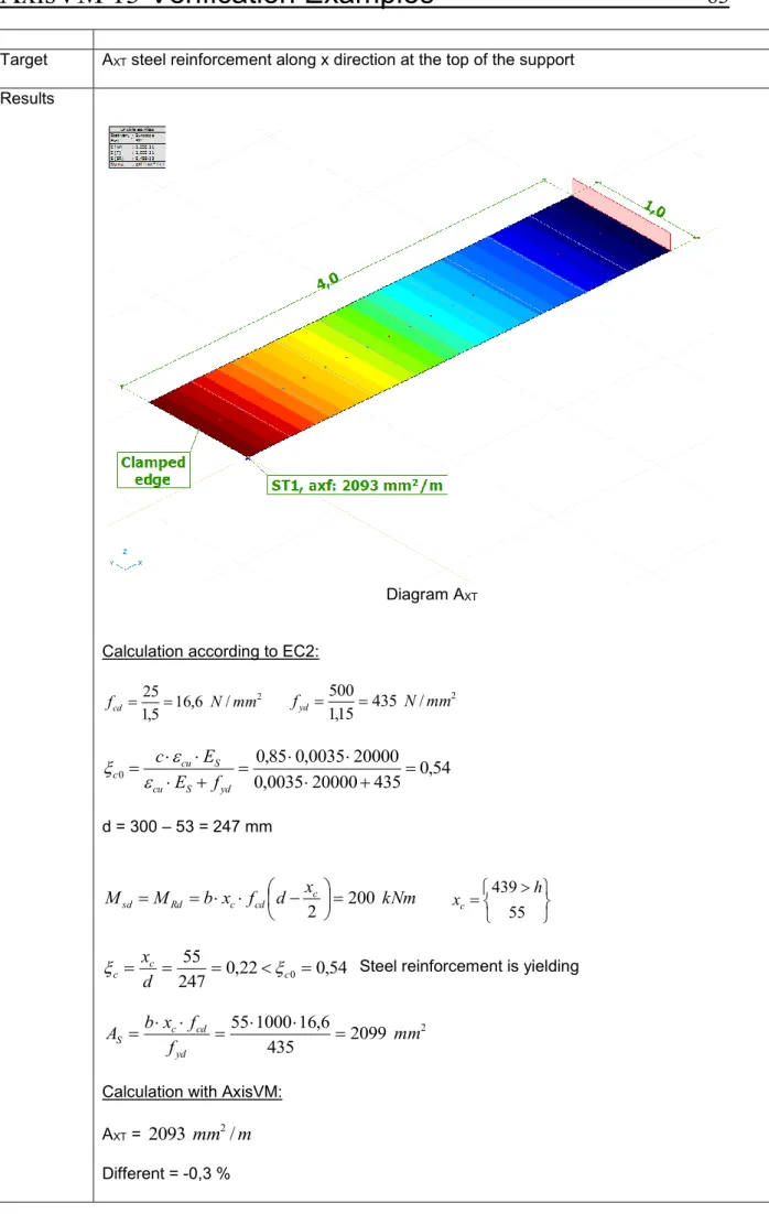
Thema Required steel reinforcement of RC plate according to EC2, EN 1992-1-1:2004.
Analysis
Type Linear analysis.
Geometry
Side view
Cross-section
Loads Pz = -50 kN point load
Boundary
Conditions Clamped cantilever plate. Fix line support on clamped edge. Nodal DOF: Plate in X-Y plane Material
Properties
Concrete: C25/30 Steel: B500A Element
types Parabolic quadrilateral plate element (heterosis)
Mesh
Target AXT steel reinforcement along x direction at the top of the support
Results
Diagram AXT
Calculation according to EC2: 2 / 6 , 16 5 , 1 25 mm N fcd 435 / 2 15 , 1 500 mm N fyd
54
,
0
435
20000
0035
,
0
20000
0035
,
0
85
,
0
0
yd S cu S cu cf
E
E
c
d = 300 – 53 = 247 mmkNm
x
d
f
x
b
M
M
c cd c Rd sd200
2
55 439 h xc54
,
0
22
,
0
247
55
0
c c cd
x
Steel reinforcement is yielding2
2099
435
6
,
16
1000
55
mm
f
f
x
b
A
yd cd c S
Calculation with AxisVM: AXT =
2093
mm
2/
m
File name: 3_10 Plastic biaxial bending interaction.axs
Thema Interaction check of simply supported beam under biaxial bending (EN 1993-1-1).
Analysis
Type Steel Design
Geometry h = 270 mm b = 135 mm tf = 10 mm tw = 7 mm l = 6000 mm A = 45,95 cm2 Wy,pl = 484,1 cm3 Wz,pl = 97 cm3
IPE270 cross section
Loads qy = 1,5 kN/m qz = 20,4 kN/m Boundary Conditions eX = eY = eZ = 0 at A eY = eZ = 0 at B Material Properties S 235 E = 21000 kN/cm2 = 0,3
Element
types Beam element
Target Interaction check taking into account plastic resistances
Results Analytical solution in the following book:
Dunai, L., Horváth, L., Kovács, N., Verőci, B., Vigh, L. G.: “Acélszerkezetek méretezése az Eurocode 3 alapján, Gyakorlati útmutató” (Design of steel structures according to
Eurocode 3, ) Magyar Mérnök Kamara Tartószerkezeti tagozata, Budapest, 2009. Exercise 3.10., page 28.
Analitical
solution AxisVM e[%]
My,Ed [kNm] 91,8 91,8 - Mz,Ed [kNm] 6,75 6,75 - Mpl,y,Rd [kNm] 113,74 113,76 +0,02 Mpl,z,Rd [kNm] 22,78 22,79 +0,04 α 2 2 - β 1 1 - capacity ratio [-] 0,948 0,947 -0,11
File name: 3_12 _MNV_Interaction.axs
Thema Interaction check of simply supported beam under normal force, bending and shear force.
(EN 1993-1-1, EN 1993-1-5) Analysis
Type Steel Design
Geometry h = 200 mm b = 200 mm tf = 15 mm tw = 9 mm l = 1400 mm A = 78,1 cm2 Av = 24,83 cm2 Iy = 5696 cm3 Wy,pl = 643 cm3
IPE270 cross section
Loads Fz = 300 kN at thirds of beam
N = 500 kN at B Boundary Conditions eX = eY = eZ = fiX = 0 at A eY = eZ = fiX =0 at B Material Properties S 235 E = 21000 kN/cm2 = 0,3 Element
types Beam element
Results Analytical solution in the following book:
Dunai, L., Horváth, L., Kovács, N., Verőci, B., Vigh, L. G.: “Acélszerkezetek méretezése az Eurocode 3 alapján, Gyakorlati útmutató” (Design of steel structures according to
Eurocode 3, ) Magyar Mérnök Kamara Tartószerkezeti tagozata, Budapest, 2009. Exercise 3.12., page 31-33.
Analytical
solution AxisVM results e[%]
NEd [kN] 500 500 - Vz,Ed [kN] 300 300 - My,Ed [kNm] 140 140 - Pure compression Npl,Rd [kN] 2148 2148 - capacity ratio [-] 0,233 0,233 - Pure shear Vpl,z,Rd [kN] 394,2 394,5 +0,08 capacity ratio [-] 0,761 0,761 - Pure bending Mpl,y,Rd [kNm] 176,8 176,7 -0,06 capacity ratio [-] 0,792 0,792 - Interaction check 0,273 0,271 -0,73 MV,Rd [kNm] 163,96 163,93 -0,02 n 0,233 0,233 - a 0,232 0,232 - MNV,Rd [kNm] 142,2 142,2 - capacity ratio [-] 0,985 0,984 -0,10
File name: 3_15 Központosan nyomott rúd - I szelvény.axs
Thema Buckling resistance of simply supported beam (EN 1993-1-1).
Analysis
Type Steel Design
Geometry h = 300 mm b = 250 mm tf = 14 mm tw = 8 mm l = 4500 mm A = 94 cm2 Iy = 19065,8cm4 Iz = 3647,1 cm4 iy = 14,1 cm iz = 6,2 cm
“I” cross section, symmetric about y and z axis
Loads Normal force at point A
NA= -1,0 kN
Boundary
Conditions eY = 0 at A eX = eY = eZ = fiX = fiZ= 0 at B kz = kw = 1 Material Properties S 235 E = 21000 kN / cm2 = 0,3 Element
types Beam element
Results Analytical solution in the following book:
Dunai, L., Horváth, L., Kovács, N., Verőci, B., Vigh, L. G.: “Acélszerkezetek méretezése az Eurocode 3 alapján, Gyakorlati útmutató” (Design of steel structures according to
Eurocode 3, ) Magyar Mérnök Kamara Tartószerkezeti tagozata, Budapest, 2009. Exercise 3.15., P. 37-39.
Analytical
solution AxisVM e[%]
y
[-] * 0,673 0,673 - z
[-] 0,771 0,769 -0,26 Χy [-] * 0,8004 0,7989 -0,19 Χz [-] 0,6810 0,6815 +0,07 Nb,Rd [kN] 1504,3 1505,3 +0,07File name: 3_21 Központosan nyomott rúd - T szelvény.axs
Thema Buckling resistance of simply supported beam (EN 1993-1-1).
Analysis
Type Steel Design
Geometry h = 180 mm b = 250 mm tf = 16 mm tw = 16 mm l = 3000 mm A = 68,8 cm2 Iy = 2394,25cm4 Iz = 2089,48 cm4 Ics= 58,71 cm4 Iw = 1108,0 cm6 iy = 5,90 cm iz = 5,51 cm
Welded “T” section, symmetric to z but not y
Loads Normal force at point A
NA= -1,0 kN Boundary Conditions eY = 0 at A eX = eY = eZ = fiX = 0 at B kz = kw = 1 Material Properties S 235 E = 21000 kN/cm2 = 0,3 Element
types Beam element
Results Analytical solution in the following book:
Dunai, L., Horváth, L., Kovács, N., Verőci, B., Vigh, L. G.: “Acélszerkezetek méretezése az Eurocode 3 alapján, Gyakorlati útmutató” (Design of steel structures according to
Eurocode 3, ) Magyar Mérnök Kamara Tartószerkezeti tagozata, Budapest, 2009. Exercise 3.21., P. 47-49.
Analitical
solution AxisVM e[%]
zs [cm] 49,0 49,0 - zw [cm] 4,10 4,04 -1,46 iw [cm] * 9,05 9,03 -0,22 y
[-] 0,542 0,542 - Χy [-] 0,8204 0,8195 -0,11 Nb,Rd,1 [kN] 1326,4 1325,0 -0,11 z
[-] * 0,667 0,667 - Χz [-] * 0,7432 0,7446 +0,19 Nb,Rd,2 [kN] * 1201,6 1203,9 +0,19File name: Külpontosan nyomott rúd - RHS szelvény.axs
Topic Buckling of a hollow cross-section beam (EN 1993-1-1).
Analysis
Type Steel Design
Geometry h = 150 mm b = 100 mm tf = 10 mm tw = 10 mm L = 4,000 m A = 43,41 cm2 Iy = 1209,8 cm4 Iz = 635,7 cm4 iy = 52,8 mm iz = 38,3 mm Wel,y = 161,3 cm3 Wel,z = 127,1 cm3 Wpl,y = 205,6 cm3 Wpl,z = 154,6 cm3
RHS 150x100x10,0 cross section (hot rolled)
Loads Bending moment at both ends of beam and axial force
NEd,C = 200 kN
MEd,A = MEd,B = 20 kNm
Boundary
Conditions eX = eY = eZ = 0, warping free at A eY = eZ = 0, warping free at B Material Properties S 275 E = 21000 kN / cm2 = 0,3 Element
types Beam element
Steel Design Parameters Buckling length: Ly = L Lz = L Lw = L
Results Analytical solution: Section class: 1.
Compression – flexural buckling
1,2040 823,48 1193,8 crz N pl N z 0,8728 1567,16 1193,8 cry N pl N y kN 1193,8 27,5 43,41 y f A Rd pl, N kN 823,5 2 400 7 , 35 6 21000 2 L z K z I E 2 z cr, N kN 1567,2 2 400 8 , 209 1 21000 2 L y K y I E 2 y cr, N
imperfection factor based on buckling curve “a” (hot rolled RHS section):
2 -2 1 : 2 2 0.2) -( 1 21 , 0 z y kN 200 x Ed, N kN 629,72 0 , 1 2 kN/cm 27,5 2 cm 43,41 0,5275 1 y f A Rd b, N 0,5275 0,7516 y z y
Bending – lateral torsional buckling
kNm 10 Ed M kNm 56,54 0 , 1 2 kN/cm 27,5 3 cm 205,6 1 y f y pl, W y Rd, pl, M 1 w k z k 1,000 1 C kNm 977,41 cr M 4 cm 7 , 35 6 2 cm kN 21000 2 4 cm 2 , 436 1 2 cm kN 8077 2 cm) (400 4 cm 635,7 6 cm 766 2 cm) (400 4 cm 7 , 35 6 2 cm kN 21000 2 1,0 cr M z I E 2 t I G 2 (kL) z I w I 2 w k z k 2 (kL) z I E 2 1 C cr M
2 , 0 LT
torsional buckling may occur
76 , 0 LT kNm kNm y Rd pl M Rd b M 0,9684 56,54 54,76 , , LT , 9684 , 0 2 LT -2 1 : LT 0,5443 2 2 LT 0.2) -LT ( LT 1
Interaction of bending and buckling
56,54kNm y Rd, pl, M Rk y, M kN 1193,8 2 kN/cm 27,5 2 cm 43,41 y f A Rk N
Equivalent uniform moment factors according to EN 1993-1-1 Annex B, Table B.3.: 0,4 1,0 0,4 0,6 my C 1,0
For members susceptible to torsional deformations the interaction factors may be calculated according to EN 1993-1-1 Annex B, Table B.2.:
1,149 1,178) ; (1,149 min yy k /1,0 1193,78 0,7531 200 0,8 1 1,0 /1,0 1193,78 0,7531 200 0,2) -(0,87 1 1,0 yy k M1 / Rk N y Ed N 0,8 1 my C M1 / Rk N y Ed N 0,2) -LT ( 1 my C yy k
0,9577 0,9577) ; (0,9490 max zy k /1,0 1193,78 0,5275 200 25 , 0 0 , 1 0,1 1 /1,0 1193,78 0,5275 200 25 , 0 0 , 1 2040 , 1 0,1 1 zy k M1 / Rk N x Ed, N 25 , 0 mLT C 0,1 1 M1 / Rk N x Ed, N 25 , 0 mLT C 0,1 1 zy k z z
z0,6674 56,54 0,9684 20 0,9577 1193,78 0,5275 200 M1 / Rk y, M Ed y, M zy k M1 / Rk N z Ed N 0,6426 56,54 0,9684 20 1,149 1193,78 0,7516 200 M1 / Rk y, M y Ed y, M yy k M1 / Rk N y Ed N
Analytical solution AxisVM e [%]
NRk = Npl,Rd [kN] 1193,8 1193,9 - y
[-] 0,873 0,870 -0,3 z
[-] 1,204 1,201 -0,2 Χy [-] 0,7516 0,7516 - Χz [-] 0,5275 0,5274 - Nb,Rd [kN] 629,7 629,7 - Mc,Rd = Mpl,Rd [kNm] 56,54 56,54 - C1 1,000 1,000 - Mcr [kNm] 977,41 977,40 - LT
[-] 0,2405 0,2405 - ΧLT [-] 0,9684 0,9684 - Mb,Rd [kNm] 54,76 54,75 - Cmy [-] 1,0 1,0 - kyy [-] 1,149 1,150 - kzy [-] 0,9577 0,9577 -Interaction capacity ratio 1 [-] 0,643 0,643 -
File name: 3_26 Külpontosan nyomott rúd - I szelvény.axs
Thema Lateral torsional buckling of a beam (EN 1993-1-1).
Analysis
Type Steel Design
Geometry h = 171 mm b = 180 mm tf = 6 mm tw = 9,5 mm L = 4,000 m A = 45,26 cm2 Iy = 2510,7 cm4 Iz = 924,6 cm4 iy = 74 mm iz = 45 mm Wel,y = 293,7 cm3 Wel,z = 102,7 cm3 Wpl,y = 324,9 cm3 Wpl,z = 156,5 cm3 Iw = 58932 cm6 It = 15 cm4 HEA180
Loads Axial force at B: Nx = -280 kN
Point load in y direction at the thirds of the beam: Fy = 5 kN
Distributed load in z direction: qz = 4,5 kNm
Boundary
Conditions eX = eY = eZ = 0, warping free at A eY = eZ = 0, warping free at B Material
Properties S 235 E = 21000 kN / cm2 = 0,3
Element
Steel Design Parameters
The elastic critical load factor is: αcr = 4,28
As αcr = 4,28 < 15 II. order analysis is required.
For this, the beam element needs to be meshed. Divison of the beam element into 4. Buckling length:
Ly = L
Lz = L
LT buckling length: Lw = L
Target Buckling check for interaction of axial force and bi-axial bending.
Results
Internal forces from the second order analysis
NEd,x = 280 kN MEd,y = 9,84 kNm MEd,z = 8,81 kNm VEd,y = 6,50 kN VEd,z = 9,61 kN
Section class: 1. Normal force 0,9424 1197,7 1063,6 crz N pl N 0,5719 3252,3 1063,6 cry N pl N kN 1063,6 23,5 45,26 y f A Rd pl, N kN 1197,7 400 924,6 21000 2 L z K z I E 2 z cr, N kN 3252,3 400 2510,7 21000 2 L y K y I E 2 y cr, N z y
based on buckling curve “b” in y direction and “c” in z direction:
kN 280 x Ed, N kN 610,62 0 , 1 2 23,5kN/cm 2 45,26cm 0,5741 1 y f A Rd,2 b, N kN 280 x Ed, N kN 904,92 0 , 1 2 23,5kN/cm 2 45,26cm 0,8508 1 y f A Rd,1 b, N 0,5741 0,8508 z y z y Bending kNm 8,81 z Ed, M kNm 36,78 0 , 1 2 kN/cm 23,5 3 cm 156,5 1 y f z pl, W z Rd, pl, M kNm 9,84 y Ed, M kNm 76,35 0 , 1 2 kN/cm 23,5 3 cm 324,9 1 y f y pl, W y Rd, pl, M
Calculation of the critical moment:
C11,132 (due to the My moment diagram)
kNm 1 , 74 1 cr M 4 cm 924,6 2 kN/cm 21000 2 4 cm 15 2 kN/cm 8077 2 cm) (400 4 cm 924,6 6 cm 58932 2 cm) (400 4 cm 924,6 2 kN/cm 21000 2 1,132 cr M z I E 2 t I G 2 (kL) z I w I 2 w k z k 2 (kL) z I E 2 1 C cr M
For rolled section, the following procedure may be used to determine the reduction factor (EN 1993-1-1,Paragraph 6.3.2.3.):
kNm kNm y Rd pl M Rd b M 0,8881 76,35 67,81 , , LT , 8881 , 0 2 LT 0.75 -2 1 : LT 0,7090 2 2 LT 0.75 0.4) -LT ( LT 1 6622 , 0 kNm 174,10 2 kN/cm 23,5 3 cm 324,9 cr M y f y W LT
Interaction of axial force and bi-axial bending
kNm 36,78 z Rd, pl, M Rk z, M kNm 76,35 y Rd, pl, M Rk y, M kN 1063,6 Rd pl, N Rk N
Equivalent uniform moment factors according to EN 1993-1-1 Annex B, Table B.3.: 0 0, in both directions
0,95 0,05 0,95 mLT C my C (distributed load) 0,90 0,10 0,90 mz C (concentrated load) 0,9383 0,9345) ; (0,9383 max zy k /1,0 1063,6 0,5741 280 25 , 0 95 , 0 0,1 1 /1,0 1063,6 0,5741 280 25 , 0 95 , 0 9424 , 0 0,1 1 zy k M1 / Rk N x Ed, N 25 , 0 mLT C 0,1 1 M1 / Rk N x Ed, N 25 , 0 mLT C 0,1 1 zy k 1,0593 1,1851) ; (1,0593 min yy k /1,0 1063,6 0,8508 280 0,8 1 0,95 /1,0 1063,6 0,8508 280 0,2) -(0,5719 1 0,95 yy k M1 / Rk N y x Ed, N 0,8 1 my C M1 / Rk N y x Ed, N 0,2) -( 1 my C yy k z z
z y0,8582 zz k 0,6 yz k 1,4303 1,478) ; (1,4303 min zz k /1,0 1063,6 0,5741 280 4 , 1 1 90 , 0 /1,0 1063,6 5741 , 0 280 0,6) -9424 , 0 (2 1 0,90 zz k
9374 , 0 3426 , 0 1362 , 0 4586 , 0 36,78 8,81 1,4303 76,35 0,8881 9,84 0,9383 1063,6 0,5741 280 M1 / Rk z, M Ed z, M zz k M1 / Rk y, M LT Ed y, M zy k M1 / Rk N z x Ed, N 0,6687 0,2056 0,1537 0,3094 36,78 8,81 0,8582 76,35 0,8881 9,84 1,0593 1063,6 0,8508 280 M1 / Rk z, M Ed z, M yz k M1 / Rk y, M LT Ed y, M yy k M1 / Rk N y x Ed, N Analytical solution AxisVM e [%] Npl,Rd [kN] 1063,6 1063,6 - Ncr,y [kN] 3252,3 3252,4 - Ncr,z [kN] 1197,7 1197,7 - λy, rel [-] 0,5719 0,5719 - λz, rel [-] 0,9424 0,9424 - Χy [-] 0,8508 0,8509 - Χz [-] 0,5741 0,5741 - Mpl,Rd,y [kNm] 76,35 76,36 - Mpl,Rd,z [kNm] 36,78 36,78 - C1 [-] 1,132 1,125 -0,6* Mcr [kNm] 174,1 173,0 -0,63 λLT, rel [-] 0,6622 0,6644 +0,3 ΧLT [-] 0,8881 0,8887 +0,1 Mb,Rd [kNm] 67,81 67,73 -0,1 Cmy = CmLt [-] 0,95 0,95 - Cmz [-] 0,90 0,95 +5,5** kyy 1,0593 1,0593 - kzz 1,4303 1,5096 +5,5*** kyz 0,8582 0,9058 +5,5*** kzy 0,9383 0,9383 -
Interaction capacity ratio 1 0,6687 0,6801 +1,7***
Interaction capacity ratio 2 0,9374 0,9564 +2,0***
* AxisVM calculates this factor using a closed form expression, while in the hand calculation C1 was derived from a table. The effect of this on the final result
(efficiency) is 10-4, thus on the safe side.
** See EC3 Annex B, Table B.3: the difference is due to the fact, that AxisVM calculates the equivalent uniform moment factor (Cmy, Cmz, CmLT) for both uniform load and
concentrated load, and then takes the higher value. The effect on the final result (efficiency) is +1~2%.
File name: Double-symmetric I - Class 4.axs
Thema Interaction check of beam in section class 4 (EN 1993-1-1, EN 1993-1-5)
Analysis
Type Steel Design
Geometry h = 1124 mm tw = 8 mm b = 320 mm tf = 12 mm L = 8,000 m A = 164,8 cm2 Iy = 326159,4 cm4 Wel,y = 5803,6 cm3
Double-symmetric welded I shape
Loads Axial force at B: N Ed,C = 700 kN
Distributed load in z direction: qz = 162,5 kNm
The internal forces in the mid-section: MEd,y = 1300 kNm, NEd,x = - 700 kN
Boundary
Conditions eX = eY = eZ = fiX = 0 at A eY = eZ = fiX = 0 at B Material Properties S 355 E = 21000 kN / cm2 ε=0,81 = 0,3 Element types Beam element
Results Analytical solution in the following book:
Dunai, L., Horváth, L., Kovács, N., Verőci, B., Vigh, L. G.: “Acélszerkezetek méretezése az Eurocode 3 alapján, Gyakorlati útmutató” (Design of steel structures according to
Eurocode 3, ) Magyar Mérnök Kamara Tartószerkezeti tagozata, Budapest, 2009. Exercise 3.4., P. 14-16.
Exercise 3.6., P. 19-21. Exercise 3.13., P. 34.
Analytical solution AxisVM e [%]
Uniform compression 0,43 0,43 - 0,831 0,858 +3,1 0,931 0,910 -2,3 140,0 142,0 +1,4 4 4 - 2,957 2,975 +0,6 0,313 0,311 -0,6 340,8 342,4 +0,5 99,98 97,46 -2,6 3549 3460 +2,6 0,2 0,2 - Uniform bending 0,43 0,43 - 0,831 0,858 +3,1 0,931 0,910 -2,3 139,95 142,0 +1,4 -0,969 -0,959 +1,0 23,09 22,84 -1,1 1,231 1,245 +1,1 0,739 0,731 -1,1 408,6 410,4 +0,4 5131 4976 -3,1 1821,5 1766,5 -3,1 0,71 0,74 +4,1 0,91 0,94 +3,3
Small differences occur because AxisVM does not take into account welding when calculating the effective section sizes.
Software Release Number: R3 Date: 17. 08. 2015.
Tested by: InterCAD Page number:
File name: Earthquake-01-EC.axs
Thema Earth-quake design using response-spectrum method.
Analysis
Type Linear frequency analysis with 5 modes. Linear static analysis.
Geometry
Top view
Perspective view Section beams: 60x40 cm
Ax=2400 cm2 Ay=2000 cm2 Az=2000 cm2
Ix=751200 cm4 Iy=720000 cm2 Iz=320000000 cm4 Section columns: 60x40 cm
Ax=2400 cm2 Ay=2000 cm2 Az=2000 cm2 Ix=751200 cm4 Iy=720000 cm2 Iz=320000 cm4
Loads Nodal masses on eight nodes. Mx=My=Mz=100000 kg
Model self-weight is excluded. qd = 1
Spectrum for X and Y direction of seismic action:
Sd [m/s2] T[s] 1,150 2,156 0,300 2,0000 0,709 T[s] Sd 1 0 1,150 2 0,2000 2,156 3 0,6000 2,156 4 1,3000 0,995 5 3,0000 0,300 6 4,0000 0,300 . . . . Boundary Conditions
Nodes at the columns bottom ends are constrained in all directions. eX=eY=eZ=fiX=fiY=fiZ=0
Material
Element
types Rib element: Three node straight prismatic beam element. Shear deformation is taken into account.
Target Compare the model results with SAP2000 v6.13 results.
The results are combined for all modes and all direction of spectral acceleration. CQC combination are used for modes in each direction of acceleration.
SRSS combination are used for combination of directions.
Results Period times of first 5 modes
Mode T[s] SAP2000 T[s] AxisVM Difference [%]
1 0,7450 0,7450 0
2 0,7099 0,7099 0
3 0,3601 0,3601 0
4 0,2314 0,2314 0
5 0,2054 0,2054 0
Modal participating mass ratios in X and Y directions
Mode X SAP2000 X AxisVM Difference % SAP2000 Y Y AxisVM Difference % 1 0,5719 0,5719 0 0,3153 0,3154 +0,03 2 0,3650 0,3650 0 0,4761 0,4760 -0,02 3 0 0 0 0,1261 0,1261 0 4 0,0460 0,0460 0 0,0131 0,0131 0 5 0,0170 0,0170 0 0,0562 0,0562 0 Summ 1,0000 1,0000 0 0,9868 0,9868 0
Internal forces at the bottom end of Column A and Column B Column A
SAP2000 Column A AxisVM Difference % Column B SAP2000 Column B AxisVM Difference %
Nx [kN] 315,11 315,15 +0,01 557,26 557,29 +0,005 Vy [kN] 280,34 280,34 0 232,88 232,88 0 Vz [kN] 253,49 253,49 0 412,04 412,04 0 Tx [kNm] 34,42 34,41 -0,03 34,47 34,46 -0,03 My [kNm] 625,13 625,12 -0,002 1038,74 1038,70 -0,004 Mz [kNm] 612,31 612,31 0 553,41 553,41 0
Support forces of Support C Support C
SAP2000 Support C AxisVM Difference %
Rx [kN] 280,34 280,34 0 Ry [kN] 253,49 253,49 0 Rz [kN] 315,11 315,15 +0,01 Rxx [kNm] 625,13 625,12 -0,002 Ryy [kNm] 612,31 612,31 0 Rzz [kNm] 34,42 34,41 -0,03 Displacements of Node D Node D
SAP2000 Node D AxisVM Difference %
eX [mm] 33,521 33,521 0 eY [mm] 19,944 19,945 +0,005 eZ [mm] 0,229 0,229 0 X [rad] 0,00133 0,00133 0 Y [rad] 0,00106 0,00106 0 Z [rad] 0,00257 0,00257 0
File name: Plastic_1.axs
Thema Plastic material
Analysis
Type Nonlinear static analysis
Geometry
Cross-section: D = 30mm
Loads Axial force at A: N
Solution control: Displacement at A Boundary Conditions eX = eY = eZ = 0 at B, C and D Material Properties S 235 E = 21000 kN / cm2 = 0,3
Linear elastic – perfectly plastic material model Element
types Truss element
Target Check the load – vertical displacement (A) curve
Results
Analytical results: [u;F(U)] AxisVM: [Axisi,1; Axisi,0]
Software Release Number: R3 Date: 17. 08. 2015.
Tested by: InterCAD Page number:
File name: Plastic_1.axs
Thema Clamped beam with plastic material under cyclic loading
Analysis
Type Nonlinear static analysis
Geometry
F
z
N
x
L = 100 cm
A B Cross-section: Z = 30mm Loads Nx = 63,333 kN; Fz = 2,666 kNSolution control: Displacement at B ez = -70 mm Increment function: 0 1 -1 1 -1,5 -1 -0,5 0 0,5 1 1,5 Boundary
Conditions eX = eY = eZ = fiX = fiY = fiZ = 0 at A Material
Properties
Steel
E = 100000 kN/cm2; ET = 1000 kN/cm2; y = 10 kN/cm2 = 0,3
Linear elastic –plastic material model Hardening rule: Isotropic hardening Element
types
Beam element
Target Check the load –displacements and beam strains curves
Results AxisVM:
-400 -300 -200 -100 0 100 200 300 -5 -4 -3 -2 -1 0 1 2 3 4 F x [kN] eX [mm] Axis beam ANSYS beam Axis Rib -20 -15 -10 -5 0 5 10 15 -80 -60 -40 -20 0 20 40 60 80 F z [ kN] eZ [mm] Axis beam ANSYS beam Axis Rib
-20 -15 -10 -5 0 5 10 15 -50 -40 -30 -20 -10 0 10 20 30 40 50 F z [ kN] eY [mm] Axis beam ANSYS beam Axis Rib -20 -15 -10 -5 0 5 10 15 -0,004 -0,003 -0,002 -0,001 0 0,001 0,002 0,003 0,004 0,005 F z [ kN] exx [] Axis beam ANSYS beam Axis Rib
Page number:
File name: XLAM_Example_2.axs
Thema Design of an XLAM shell (EC5).
Analysis
Type Linear analysis.
Geometry
Top view (x-y plane)
Loads P = -100 kN concentrated force acting at point (x = 9.0 m, y = 2.5 m)
Pz = -5.00 kN/m2 uniform load
PX = -5.00 kN/m line load on the right edge Boundary
Conditions eZ =0 along all edges eX = 0 along the left edge eY = 0 along the top edge The remaining DOFs are left free. Material
Properties
Material quality equals to C24 timber. Section
Properties MM 7s/240 XLAM section with “x” oriented top layer grain direction and Service Class 2, producing an overall thickness of 240 mm. Element
types Shell element (Parabolic quadrilateral, heterosis)
Mesh
Average element length is 0.2 m.
Stresses calculated with Axis VM
Normal stresses in x direction from bending and normal forces [N/mm2]
Normal stresses in y direction from bending [N/mm2]
Shear stresses in x and y direction [N/mm2]
Rolling shear stresses in x and y direction [N/mm2]
- 2.501 2.501 - 0.0307 - 7.525 7.525 - 0.049 0.047 - 0.0005 0.0050
Load-duration class : permanent
System strength factor1 : ksys = Min(1.2, 1+0.025*7) = 1.175
Partial safety factor of the material :
γ
M = 1.33 , mod , 3 , 90 , mod , 90 , 3 , 0 , mod , 0 , 3 , 90 , mod , 90 , 3 , 0 , mod , 0 , 3 , mod , 3 , mod ,
10
54
.
461
10
85
.
1153
10
31
.
9692
10
92
.
216
10
31
.
7592
10
15
.
1846
10
38
.
13015
M k r d r M k c d c M k c d c M k t sys d t M k t sys d t M k v d v M k m sys d mf
k
f
f
k
f
f
k
f
f
k
k
f
f
k
k
f
f
k
f
f
k
k
f
M-N efficiency (hand calculation)
5782
.
0
10
38
.
13015
525
.
7
1952
.
0
10
31
.
9692
0307
.
0
10
38
.
13015
501
.
2
3 , max, , 3 3 , max, , , max, ,
d m d my d t d cx d m d mxf
f
f
Max(0.1952, 0.5782) = 0.5782Shear efficiency (hand calculation)
02545
.
0
10
15
.
1846
047
.
0
02654
.
0
10
15
.
1846
049
.
0
3 , max, , 3 , max, ,
d v d yz d v d xzf
f
Max(0.02654, 0.02545) = 0.026541 : ksys = Min(1.1, 1+0.025*n) if NTC design code is selected kmod = 0.6
Rolling shear efficiency (hand calculation)
01076
.
0
10
54
.
461
005
.
0
001083
.
0
10
54
.
461
0005
.
0
3 , max, , 3 , max, ,
d r d ry d r d rxf
f
Max(0.001083, 0.01076) = 0.01076Maximum efficiency from hand calculations
Max(0.5782, 0.02654, 0.01076) = 0.5782
Efficiency calculated with Axis VM compared to the results from the previous hand calculations
x y Description AxisVM hand calculations Diff [%]
M-N efficiency 7.043 m